记录P3AT机器人相关参数及操作
轮胎气压:
All Pioneer 3-DX robots come with foam-filled solid tires with knobby treads.7 Pioneer 3-AT tires are pneumatic so that you may configure your robot for differing terrains. In any configuration, be careful to inflate the 3-AT tires evenly and adjust the respective DriftFactor, TicksMM and RevCount FLASH parameters for proper operation. We ship Pioneer 3-AT’s with the tires inflated to 23 psi each.
参数文件:
For Pioneer 3’s, the ARIA-parameter file’s names are p3dx-sh.p or p3at-sh.p.
PID参数:
The P-term value Kp increases the overall gain of the system by amplifying the position error. Large gains will have a tendency to overshoot the velocity goal; small gains will limit the overshoot but causethe system to become sluggish. We’ve found that a fully loaded robot works best with a Kp setting of around 15 to 30, whereas a lightly loaded robot may work best with Kp in the range of 20 to 50.
The D-term Kv provides a PID gain factor that is proportional to the output velocity. It has the greatest effect on system damping and minimizing oscillations within the drive system. The term usually is the first to be adjusted if you encounter unsatisfactory drive response. Typically, we find Kv to work best in the range of 10 to 30 for lightly to heavily loaded robots, respectively. If your robot starts to vibrate or shutter, reduce Kv.
The I-Term Ki moderates any steady state errors thereby limiting velocity fluctuations during the course of a move. At rest, your robot will seek to “zero out” any command position error. Too large of a Ki factor will cause an excessive windup of the motor when the load changes, such as when climbing
over a bump or accelerating to a new speed. Consequently, we typically use a minimum value for Ki in the range of 0 to 10 for lightly to heavily loaded robots respectively.
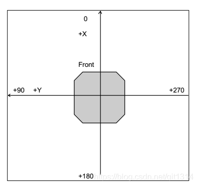
默认里程计坐标:(非ros node)
DriftFactor, RevCount, and TicksMM
Three client commands let you change, albeit momentarily for the current client-server connection,
those values that affect translation, rotation and drift in your robot. TicksMM is the number of
encoder ticks per millimeter tire rotation for translation speed and distance computations. The default
FLASH value can be changed on-the-fly during a client connection session with the TICKSMM client
command #93 and unsigned integer value.
DriftFactor is a signed value in 1/8192 increments that gets added to or subtracted from the left
wheel encoder’s ticks to correct for tire circumference differences and consequent translation and
rotation drift. DriftFactor defaults to its FLASH value on start up or reset, and can be changed onthe-fly with the DRIFTFACTOR client command #89 with signed integer argument.
The RevCount parameter is the differential number of encoder ticks for a 180-degree rotation of the
robot and is used to compute and execute headings. Like DriftFactor and TicksMM, RevCount
defaults to its FLASH value on startup or reset, and can be changed on-the-fly with the REVCOUNT
client command #88 and unsigned integer argument.
ARCOS uses the ticksMM and revCount parameters to convert your platform-independent speed and
rotation commands—typically expressed in millimeters or degrees, respectively—into platformdependent units. And it uses driftFactor to compensate for tire differences.
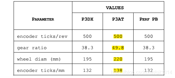
The ticksMM value is the number of encoder pulses (“ticks”) per millimeter of wheel rotation. The value is, of course, dependent upon the wheel encoder’s resolution, the motor-to-wheel gear ratio and the wheel’s diameter.

The revCount value is the number of encoder ticks for a 180-degree turn of the robot. It depends on a number of factors, principally the length of the wheel base which may change due to payload, tire wear, operating surface and so on.
The driftFactor is a value in 1/8192 units that gets added or subtracted from the left-wheel
encoder count at each motor cycle. In doing so, it compensates for tire difference and thereby
straightens the robot’s translation forward and backward.
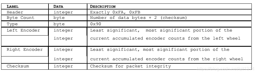
编码器
Pioneer 3 drive systems use high-speed, high-torque, reversible DC motors, each equipped with a highresolution optical quadrature shaft encoder for precise position and speed sensing and advanced dead-reckoning. Motor gearhead ratios, encoder ticks-per-revolution and tire sizes vary by robot model. However, ARCOS can correct for tire mismatches and convert most client commands and reported server information from platform-independent distance and heading units into platformdependent encoder ticks, as expressed in the DriftFactor, TicksMM and RevCount FLASH parameters.
简易标定
1 TIRE INFLATION
Maintain even tire inflation for proper navigation of your Pioneer 3-AT. We ship with each pneumatic tire inflated to 23 psi. If you change the inflation, remember to adjust the driftFactor, ticksMM, and revCount FLASH values.
2 CALIBRATING YOUR ROBOT
Your robot comes with FLASH parameters adjusted for operation on smooth, flat surfaces with its original payload. If you operate your robot on some different surface and with lighter or heavier loads, you probably will need to recalibrate many of its operating parameters, such as driftFactor, revCount, ticksMM and the PIDs.
The ARIA demo program has two modes to help you do that. In ‘p’osition mode, demo displays current heading and position. Press the ‘r’ key to reset these to 0 at any time. Press the right or left arrow key to have the robot rotate 90 degrees either clockwise or counterclockwise, respectively. The up and down arrow keys tell the robot to advance forward or backward one meter, respectively.
ARIA demo’s ‘d’irect mode lets you change the variety of operating parameters on-the-fly by letting you send an ARCOS client command number and value to be used during the current session. To replace the default values in FLASH, use ARCOScf.
Accordingly, to properly calibrate your robot, first use ARCOScf and record and save on disk the current values for the respective parameters, such as for driftFactor and revCount. Then connect with the ARIA demo and engage position mode to move the robot. As accurately as possible, measure its actual motion and position and use demo’s direct mode to adjust the reported values for your robot’s current configuration and operating environment.
For example, start with driftFactor since its value affects both ticksMM and revCount. Draw a
line on the floor parallel to the robot’s translation travel and drive the robot forward or back at least
five meters. Adjust driftFactor (command #89) to minimize the robot’s drift off that line.
Then drive the robot forward or back one or more meters and compare its actual translation distance
you accurately measure with demo’s ARCOS-reported distance (x) in millimeters. Adjust ticksMM
(command #93) so that the numbers match.
Likewise, rotate your robot and compare your measured rotation angle to the reported heading (th).
Adjust revCount–the measure of differential encoder ticks to achieve 180-degrees rotation–
accordingly (command #88).
Finally, drive the robot around and adjust its PID, velocity and acceleration values to achieve the
desired performance for the operating configuration.
When you are satisfied that the robot moves and rotates the proper distances and headings, and
drives with the proper performance, commit those new values into their related FLASH parameters in
your robot with ARCOScf and don’t forget to save a copy in a .rop file for later reference
超声波
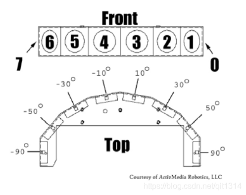
Natively, ARCOS-based robots support up to four sonar arrays, each with up to eight transducers that
provide object detection and range information for collision avoidance, features recognition,
localization, and navigation. The sonar positions in all Pioneer 3 sonar arrays are fixed: one on each
side, and six facing outward at 20-degree intervals. Together, fore and aft sonar arrays provide 360
degrees of nearly seamless sensing for the platform.
Each sonar array’s transducers are multiplexed: Only one disc per array is active at a time, but all four
arrays fire one transducer simultaneously. The sonar ranging acquisition rate is adjustable, normally
set to 25 Hz (40 milliseconds per transducer per array). Sensitivity ranges from 10 centimeters (six
inches) to over four meters, depending on the ranging rate.