1、本博客根据《WPF编程宝典:使用C# 2012和.NET 4.5 第4版》书本提供关于绘图12章/13章/14章的内容以及其例程,整理出关于绘画的结构图、程序代码如下:

2、12章的代码,集中放在一起(运行时可见)(参考pro-wpf-4.5-in-csharp或刘铁猛的书本)。
例子A(刘铁猛)
<Window x:Class="Drawing.MainWindow"
        xmlns="http://schemas.microsoft.com/winfx/2006/xaml/presentation"
        xmlns:x="http://schemas.microsoft.com/winfx/2006/xaml"
        xmlns:d="http://schemas.microsoft.com/expression/blend/2008"
        xmlns:mc="http://schemas.openxmlformats.org/markup-compatibility/2006"
        xmlns:local="clr-namespace:Drawing"
        mc:Ignorable="d"
        Title="MainWindow" Height="1080" Width="1920">


    <!-- 以下代码参考《深入浅出》WPF 刘铁猛著 -->
        <TabControl Background="Transparent" BorderBrush="Transparent" x:Name="tabcontrol">
        <TabItem Header="Line直线"  Width="120" Height="30" FontSize="16" FontFamily="Microsoft YaHei">
            <Grid>
                <!-- X1是系统Line控件自带的属性 -->
                <!-- Stroke继承了Brush -->
                <Line X1="10" Y1="20" X2="260" Y2="20" Stroke="red" StrokeThickness="10"/>
                <Line X1="10" Y1="40" X2="260" Y2="40" Stroke="Orange" StrokeThickness="6"/>
                <Line X1="10" Y1="60" X2="260" Y2="60" Stroke="Green" StrokeThickness="3"/>
                <Line X1="10" Y1="80" X2="260" Y2="80" Stroke="Purple" StrokeThickness="2"/>
                <Line X1="10" Y1="100" X2="260" Y2="100" Stroke="Black" StrokeThickness="3"/>
                <!-- StrokeDashArray="10" 表示间隔为10的虚线 -->
                <Line X1="10" Y1="120" X2="260" Y2="120" StrokeDashArray="3" Stroke="Black" StrokeThickness="1"/>
                <Line X1="10" Y1="140" X2="260" Y2="140" StrokeDashArray="5" Stroke="Black" StrokeThickness="1"/>
                <!-- StrokeEndLineCap="Round" 表示末端的形状 -->
                <Line X1="10" Y1="160" X2="260" Y2="160" StrokeEndLineCap="Round" Stroke="Black" StrokeThickness="6"/>
                <Line X1="10" Y1="180" X2="260" Y2="180" StrokeEndLineCap="Triangle" Stroke="Black" StrokeThickness="8"/>
                <Line X1="10" Y1="200" X2="260" Y2="200" StrokeEndLineCap="Flat" StrokeThickness="6">
                <Line.Fill>
                    <RadialGradientBrush>
                        <GradientStop Color="Black" Offset="0"/>
                        <GradientStop Color="White" Offset="1"/>
                    </RadialGradientBrush>
                </Line.Fill>
                <Line.Stroke>
                        <LinearGradientBrush StartPoint="0,0.5" EndPoint="1,0.5">
                            <GradientStop Color="#FF1B1BBD" Offset="0.5"/>
                            <GradientStop Color="#FFA7F00C" Offset="0.75"/>
                        </LinearGradientBrush>
                    </Line.Stroke>
                </Line>
            </Grid>
        </TabItem>
        <TabItem Header="Rectangle矩形"  Width="120" Height="30" FontSize="16" FontFamily="Microsoft YaHei">
            <Grid >
                <Grid.RowDefinitions>
                    <RowDefinition Height="180"/>
                    <RowDefinition Height="10"/>
                    <RowDefinition Height="180"/>
                    <RowDefinition Height="10"/>
                    <RowDefinition Height="180"/>

                </Grid.RowDefinitions>
                <Grid.ColumnDefinitions>
                    <ColumnDefinition Width="180"/>
                    <ColumnDefinition Width="10"/>
                    <ColumnDefinition Width="180"/>
                    <ColumnDefinition Width="10"/>
                    <ColumnDefinition Width="180"/>
                    <ColumnDefinition Width="10"/>
                    <ColumnDefinition Width="180"/>
                    <ColumnDefinition Width="10"/>
                    <ColumnDefinition Width="180"/>
                </Grid.ColumnDefinitions>

                <!-- Stroke表示矩形的边,Fill表示对矩形进行填充 -->
                <Rectangle Grid.Row="0" Grid.Column="0" Stroke="Black" Fill="LightBlue"/>

                  <!--线性渐变-->
                <Rectangle Grid.Row="0" Grid.Column="2">
                    <Rectangle.Fill>
                        <!--LinearGradientBrush线性渐变 StartPoint设置渐变起点-->
                        <LinearGradientBrush StartPoint="0,0" EndPoint="1,1">
                            <GradientStop Color="#ffb6f8f1" Offset="0"/>
                            <GradientStop Color="#ff0082bd" Offset="0.25"/>
                            <GradientStop Color="#ff95deff" Offset="0.75"/>
                            <GradientStop Color="#ff004f72" Offset="1.5"/>
                        </LinearGradientBrush>
                    </Rectangle.Fill>
                </Rectangle>

                <!-- 径向渐变 -->
                <Rectangle Grid.Row="0" Grid.Column="4">
                    <Rectangle.Fill>
                        <!-- RadiusX RadiusY设置渐变的半径,与线性渐变StartPoint EndPoint的功能一样 -->
                            <RadialGradientBrush RadiusX="0.5" RadiusY="0.5">
                            <GradientStop Color="#ffb6f8f1" Offset="0"/>
                            <GradientStop Color="#ff0082bd" Offset="0.25"/>
                            <GradientStop Color="#ff95deff" Offset="0.75"/>
                            <GradientStop Color="#ff004f72" Offset="1.5"/>
                        </RadialGradientBrush>
                    </Rectangle.Fill>
                </Rectangle>

                <!-- 图片填充 -->
                <Rectangle Grid.Row="2" Grid.Column="0" Stroke="Black">
                    <Rectangle.Fill>
                          <ImageBrush ImageSource="Icons/p1.jpg" Viewport="0, 0, 0.5, 0.5" TileMode="FlipX" ViewportUnits="RelativeToBoundingBox"/>
                    </Rectangle.Fill>
                </Rectangle>

                <!-- 矢量图填充:圆形 -->
                <Rectangle Grid.Row="2" Grid.Column="2">
                    <Rectangle.Fill>
                        <!--DrawingBrush 矢量图填充-->
                            <DrawingBrush Viewport="0, 0, 0.5, 0.5" TileMode="Tile">
                            <DrawingBrush.Drawing>
                                <GeometryDrawing Brush="Red">
                                    <GeometryDrawing.Geometry>
                                        <EllipseGeometry RadiusX="10" RadiusY="10"/>
                                    </GeometryDrawing.Geometry>
                                </GeometryDrawing>
                            </DrawingBrush.Drawing>
                        </DrawingBrush>
                    </Rectangle.Fill>
                </Rectangle>

                <!-- 无填充,举行的边框渐变 -->
                <Rectangle Grid.Row="2" Grid.Column="4" StrokeThickness="10">
                    <Rectangle.Stroke>
                        <LinearGradientBrush StartPoint="0 0" EndPoint="1  1">
                            <GradientStop Color="White" Offset="0.3"/>
                            <GradientStop Color="Blue" Offset="1"/>
                        </LinearGradientBrush>
                    </Rectangle.Stroke>
                </Rectangle>

                <!-- 矢量图填充 -->
                <Rectangle Grid.Row="0" Grid.Column="6">
                    <Rectangle.Fill>
                        <DrawingBrush>
                            <DrawingBrush.Drawing>
                                <GeometryDrawing>
                                    <GeometryDrawing.Pen>
                                        <Pen Brush="Blue" Thickness="1" />
                                    </GeometryDrawing.Pen>
                                    <GeometryDrawing.Geometry>
                                        <RectangleGeometry Rect="0,0,100,50" />
                                    </GeometryDrawing.Geometry>
                                </GeometryDrawing>
                            </DrawingBrush.Drawing>
                        </DrawingBrush>
                    </Rectangle.Fill>
                </Rectangle>


                <!-- 矢量图填充 -->
                <Image Grid.Row="0" Grid.Column="8">
                    <Image.Source>
                        <DrawingImage>
                            <DrawingImage.Drawing>
                                <GeometryDrawing Brush="LightBlue">
                                    <GeometryDrawing.Pen>
                                        <Pen Brush="Blue" Thickness="2" />
                                    </GeometryDrawing.Pen>
                                    <GeometryDrawing.Geometry>
                                        <RectangleGeometry Rect="0 0 100 200" />
                                    </GeometryDrawing.Geometry>
                                </GeometryDrawing>
                            </DrawingImage.Drawing>
                        </DrawingImage>
                    </Image.Source>
                </Image>
            </Grid>
        </TabItem>

        <TabItem Header="Ellipse椭圆"  Width="120" Height="30" FontSize="16" FontFamily="Microsoft YaHei">
            <Grid>
                <!--<TextBlock Text="与自定义矢量图无关,不再细化,即没有用到DrawingBrush" HorizontalAlignment="Center" Height="20" Margin="745,391,733,600" />-->
                <Ellipse Stroke="Gray" Width="140" Height="140" Cursor="Hand" ToolTip="A Ball" >
                    <Ellipse.Fill>
                        <RadialGradientBrush GradientOrigin="0.2, 0.8" RadiusX="0.75" RadiusY="0.75">
                            <RadialGradientBrush.RelativeTransform>
                                <TransformGroup>
                                    <RotateTransform Angle="90" CenterX="0.5" CenterY="0.5"/>
                                </TransformGroup>

                            </RadialGradientBrush.RelativeTransform>
                        </RadialGradientBrush>
                    </Ellipse.Fill>
                </Ellipse>
            </Grid>
        </TabItem>
    </TabControl>
</Window>
例子B1 GeometryGroup
功能描述:利用GeometryGroup画组合图。FillRule="EvenOdd"表示在矩形框内有一个椭圆的洞。
  <Canvas>
    <TextBlock Canvas.Top="50" Canvas.Left="20" FontSize="25" FontWeight="Bold">Hello There</TextBlock>
        <Path Fill="Yellow" Stroke="Blue" StrokeThickness="2" Margin="5" Canvas.Top="10" Canvas.Left="10">
            <Path.Data>
                <GeometryGroup FillRule="EvenOdd">
                    <RectangleGeometry Rect="0 0 100 100"></RectangleGeometry>
                    <EllipseGeometry Center="40 50" RadiusX="35" RadiusY="25"></EllipseGeometry>
                </GeometryGroup>
            </Path.Data>
        </Path>
    </Canvas>
效果图:

例子B2 CombinedGeometry基础篇
功能描述:利用CombinedGeometry画组合图。 GeometryCombineMode表示四种组合效果图。
 <Window.Resources>
    <RectangleGeometry x:Key="rect" Rect="0 0 100 100"></RectangleGeometry>
    <EllipseGeometry x:Key="ellipse" Center="85 50" RadiusX="65" RadiusY="35"></EllipseGeometry>
  </Window.Resources>
    <Grid Margin="5" TextBlock.FontSize="16">
      <Grid.RowDefinitions>
        <RowDefinition Height="Auto"></RowDefinition>
        <RowDefinition Height="Auto"></RowDefinition>
        <RowDefinition Height="Auto"></RowDefinition>
        <RowDefinition Height="Auto"></RowDefinition>
      </Grid.RowDefinitions>
      <Grid.ColumnDefinitions>
        <ColumnDefinition Width="Auto"></ColumnDefinition>
        <ColumnDefinition Width="Auto"></ColumnDefinition>
      </Grid.ColumnDefinitions>

      <Path Fill="Yellow" Stroke="Blue" Margin="5">
        <Path.Data>
          <CombinedGeometry GeometryCombineMode="Union"
            CombinedGeometry.Geometry1="{StaticResource rect}"
            CombinedGeometry.Geometry2="{StaticResource ellipse}">
          </CombinedGeometry>
        </Path.Data>
      </Path>
      <TextBlock Grid.Column="1" Margin="10" VerticalAlignment="Center">Union</TextBlock>

      <Path Grid.Row="1" Fill="Yellow" Stroke="Blue" Margin="5">
        <Path.Data>
          <CombinedGeometry GeometryCombineMode="Intersect"
            CombinedGeometry.Geometry1="{StaticResource rect}"
            CombinedGeometry.Geometry2="{StaticResource ellipse}">
          </CombinedGeometry>
        </Path.Data>
      </Path>
      <TextBlock Grid.Row="1" Grid.Column="1" Margin="10" VerticalAlignment="Center">Intersect</TextBlock>

      <Path Grid.Row="2" Fill="Yellow" Stroke="Blue" Margin="5">
        <Path.Data>
          <CombinedGeometry GeometryCombineMode="Xor"
            CombinedGeometry.Geometry1="{StaticResource rect}"
            CombinedGeometry.Geometry2="{StaticResource ellipse}">
          </CombinedGeometry>
        </Path.Data>
      </Path>
      <TextBlock Grid.Row="2" Grid.Column="1" Margin="10" VerticalAlignment="Center">Xor</TextBlock>

      <Path Grid.Row="3" Fill="Yellow" Stroke="Blue" Margin="5">
        <Path.Data>
          <CombinedGeometry GeometryCombineMode="Exclude"
            CombinedGeometry.Geometry1="{StaticResource rect}"
            CombinedGeometry.Geometry2="{StaticResource ellipse}">
          </CombinedGeometry>
        </Path.Data>
      </Path>
      <TextBlock Grid.Row="3" Grid.Column="1" Margin="10" VerticalAlignment="Center">Exclude</TextBlock>

    </Grid>
效果图:

例子B3 CombinedGeometry高级篇
功能描述:利用CombinedGeometry嵌套Geometry1或Geometry2,然后Geometry1或Geometry2内再嵌套CombinedGeometry。最后在CombinedGeometry内由嵌套了Geometry1或Geometry2。即ABABABABABA的嵌套方式,实现复杂图形的绘画。

效果图:

 <StackPanel Margin="5">
        <Path Fill="Yellow" Stroke="Blue">
            <Path.Data>
                <!-- 环形与矩形组合在一起 -->
                <CombinedGeometry GeometryCombineMode="Union">
                    <!--大圆减去小圆,得到一个环形-->
                    <CombinedGeometry.Geometry1>
                        <CombinedGeometry GeometryCombineMode="Exclude">
                            <CombinedGeometry.Geometry1>
                                <EllipseGeometry Center="50 50" RadiusX="50" RadiusY="50"></EllipseGeometry>
                            </CombinedGeometry.Geometry1>
                            <CombinedGeometry.Geometry2>
                                <EllipseGeometry Center="50 50" RadiusX="40" RadiusY="40"></EllipseGeometry>
                            </CombinedGeometry.Geometry2>
                        </CombinedGeometry>
                    </CombinedGeometry.Geometry1>
                    <!--放置矩形-->
                    <CombinedGeometry.Geometry2>
                        <RectangleGeometry Rect="44 5 10 90">
                            <RectangleGeometry.Transform>
                                <RotateTransform Angle="45" CenterX="50" CenterY="50"></RotateTransform>
                            </RectangleGeometry.Transform>
                        </RectangleGeometry>
                    </CombinedGeometry.Geometry2>
                </CombinedGeometry>
            </Path.Data>
        </Path>
    </StackPanel>
例子B4 PathGeometry(最强大的绘图类)
1、PathGeometry可以放置多个元素。其中, IsClosed="True"表示起点与终点闭合。
2、PathGeometry类,可以用路径微语言来进一步精简描述。路径微语言(英文/中文表格):


功能描述:用三点连线,画三角形。
<Window x:Class="Drawing.MiniLanguage"
    xmlns="http://schemas.microsoft.com/winfx/2006/xaml/presentation"
    xmlns:x="http://schemas.microsoft.com/winfx/2006/xaml"
    Title="MiniLanguage" Height="390" Width="336"
    >
  <StackPanel>
    <!--方法1-->
    <Path Stroke="Blue">
      <Path.Data>
        <PathGeometry>
            <!--左边三角-->
            <PathFigure IsClosed="True" StartPoint="10,100">
                <LineSegment Point="100,100" />
                <LineSegment Point="100,50" />
            </PathFigure>
            <!--右边三角-->
            <PathFigure IsClosed="True" StartPoint="200,100">
                <LineSegment Point="100,100" />
                <LineSegment Point="100,50" />
            </PathFigure>
            <!--下边三角-->
            <PathFigure IsClosed="True" StartPoint="100,150">
                <LineSegment Point="100,100" />
                <LineSegment Point="10,100" />
            </PathFigure>
        </PathGeometry>
      </Path.Data>
    </Path>

    <!-- 方法2 非精简的路径微语言/路径描述语言,画三角型 -->
    <Path Stroke="Blue">
      <Path.Data>
        <PathGeometry Figures="M 10,100 L 100,100 L 100,50 Z"></PathGeometry>
      </Path.Data>
    </Path>

    <!-- 方法3 精简的路径微语言/路径描述语言,画三角型 -->
    <!-- M 10,100 表示创建一个 PathFigure,并设置起点为(10,100)-->
        <!-- L 100,100 L 100,50 表示创建两个线段。 坐标尽量用逗号隔开。 -->
    <!-- Z 表示结束PathFigure -->
    <Path Stroke="Blue" Data="M 10,100 L 100,100 L 100,50 Z"/>

  </StackPanel>
</Window>
效果图:

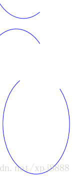
例子B5 PathGeometry(弧线)
功能描述:用PathGeometry画两段弧线。
<Window x:Class="Drawing.SimpleArc"
    xmlns="http://schemas.microsoft.com/winfx/2006/xaml/presentation"
    xmlns:x="http://schemas.microsoft.com/winfx/2006/xaml"
    Title="SimpleArc" Height="1200" Width="1200"
    >
    <StackPanel Margin="0,0,0,-203">

        <Path Stroke="Blue" StrokeThickness="3">
            <Path.Data>
                <PathGeometry>
                    <PathGeometry.Figures>
                        <PathFigureCollection>
                            <PathFigure IsClosed="False" StartPoint="250,150" >
                                <PathFigure.Segments>
                                    <PathSegmentCollection>
                                        <!-- SweepDirection="Clockwise"表示起点到终点顺时针的方式画图 -->
                                        <ArcSegment Point="10,100" Size="200,300" SweepDirection="Clockwise" />
                                    </PathSegmentCollection>
                                </PathFigure.Segments>
                            </PathFigure>
                        </PathFigureCollection>
                    </PathGeometry.Figures>
                </PathGeometry>
            </Path.Data>
        </Path>


        <Path Stroke="Blue" StrokeThickness="3" >
            <Path.Data>
                <PathGeometry>
                    <!-- IsClosed="False"表示起点与终点不闭合。 -->
                    <PathFigure IsClosed="False" StartPoint="250,150" >
                        <!-- Size="200,300" 表示椭圆的X/Y半径。SweepDirection="Counterclockwise"表示逆时针。 -->
                        <ArcSegment Point="10,100" Size="200,300" SweepDirection="Counterclockwise" />
                    </PathFigure>
                </PathGeometry>
            </Path.Data>
        </Path>

        <Path Stroke="Blue" StrokeThickness="3" Margin="100">
            <Path.Data>
                <PathGeometry>
                    <PathFigure IsClosed="False" StartPoint="250,150" >
                        <!-- IsLargeArc="True" 表示顺时针的画大弧线 -->
                        <ArcSegment Point="10,100" Size="200,300" SweepDirection="Clockwise" IsLargeArc="True"/>
                    </PathFigure>
                </PathGeometry>
            </Path.Data>
        </Path>
    </StackPanel>
</Window>
效果图:
例子B6 PathGeometry(塞贝尔曲线)
功能描述:用PathGeometry画一段塞贝尔曲线。
<Window x:Class="Drawing.BezierCurve"
    xmlns="http://schemas.microsoft.com/winfx/2006/xaml/presentation"
    xmlns:x="http://schemas.microsoft.com/winfx/2006/xaml"
    Title="BezierCurve" Height="264" Width="281.6"
    >
    <Canvas>

        <Path Stroke="Blue" StrokeThickness="5" Canvas.Top="20">
            <Path.Data>
            <PathGeometry>
                <PathGeometry.Figures>
                        <PathFigure StartPoint="10,10">
                            <!--Point1="130,30"表示起点切线所经过的辅助点。Point2="40,140"表示终点切线所经过的辅助点。Point3="150,150"表示终点-->
                        <BezierSegment Point1="130,30" Point2="40,140" Point3="150,150"></BezierSegment>
                    </PathFigure>
                </PathGeometry.Figures>
            </PathGeometry>
            </Path.Data>
        </Path>

        <Path Stroke="Green" StrokeThickness="2" StrokeDashArray="5 2" Canvas.Top="20">
            <Path.Data>
            <GeometryGroup>
                <LineGeometry StartPoint="10,10" EndPoint="130,30"></LineGeometry>
                <LineGeometry StartPoint="40,140" EndPoint="150,150"></LineGeometry>
            </GeometryGroup>
            </Path.Data>
        </Path>
        <Path Fill="Black" Stroke="Red" StrokeThickness="10"  Canvas.Top="20" Height="500" Width="300">
            <Path.Data>
            <GeometryGroup>
                <EllipseGeometry Center="130,30" ></EllipseGeometry>
                <EllipseGeometry Center="40,140"></EllipseGeometry>
            </GeometryGroup>
            </Path.Data>
        </Path>
    </Canvas>
</Window>
效果图:

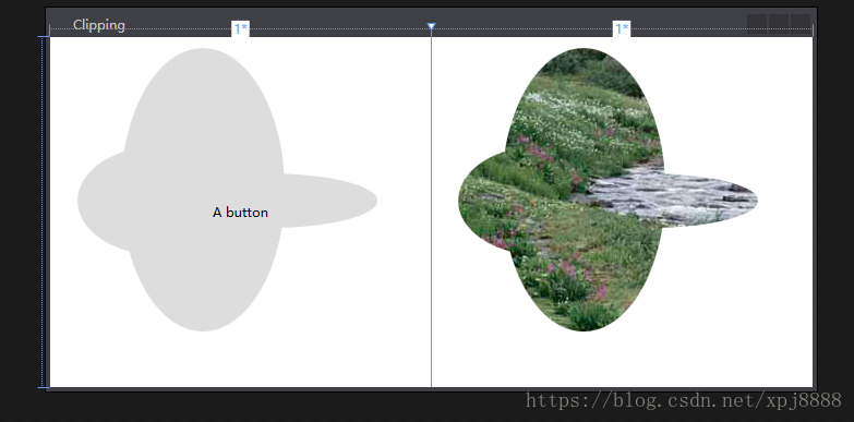
例子B7 Clipping(裁剪)
功能描述:Clipping包含三个例子,B7.1(固定的裁剪)B7.2(Viewbox比例裁剪)
B7.1

<Window x:Class="Drawing.Clipping"
    xmlns="http://schemas.microsoft.com/winfx/2006/xaml/presentation"
    xmlns:x="http://schemas.microsoft.com/winfx/2006/xaml"
    Title="Clipping" Height="352" Width="707.2"
    >
  <Window.Resources>
    <GeometryGroup x:Key="clipGeometry" FillRule="Nonzero">
      <EllipseGeometry RadiusX="75" RadiusY="50" Center="100,150"></EllipseGeometry>
      <EllipseGeometry RadiusX="100" RadiusY="25" Center="200,150"></EllipseGeometry>
      <EllipseGeometry RadiusX="75" RadiusY="130" Center="140,140"></EllipseGeometry>
    </GeometryGroup>
  </Window.Resources>
  <Grid>
    <Grid.ColumnDefinitions>
      <ColumnDefinition></ColumnDefinition>
      <ColumnDefinition></ColumnDefinition>
    </Grid.ColumnDefinitions>

    <Button Clip="{StaticResource clipGeometry}">A button</Button>
    <Image Grid.Column="1" Clip="{StaticResource clipGeometry}"
           Stretch="None"  Source="creek.jpg"></Image>
  </Grid>
</Window>


B7.2

<Window x:Class="Drawing.ClippingWithViewbox"
    xmlns="http://schemas.microsoft.com/winfx/2006/xaml/presentation"
    xmlns:x="http://schemas.microsoft.com/winfx/2006/xaml"
    Title="ClippingWithViewbox" Height="335.2" Width="401.6"
    >
  <Window.Resources>
    <GeometryGroup x:Key="clipGeometry" FillRule="Nonzero">
      <EllipseGeometry RadiusX="75" RadiusY="50" Center="100,150"></EllipseGeometry>
      <EllipseGeometry RadiusX="100" RadiusY="25" Center="200,150"></EllipseGeometry>
      <EllipseGeometry RadiusX="75" RadiusY="130" Center="140,140"></EllipseGeometry>
    </GeometryGroup>
  </Window.Resources>
  <Grid>
    <Viewbox >
      <Button Width="350" Height="350" Clip="{StaticResource clipGeometry}">A button</Button>
    </Viewbox>
  </Grid>
</Window>
效果图:
例子B8 Drawing类
功能描述:放置两个按钮,按钮背景为DrawingBrush元素或DrawingImage元素,并都为该元素添加GeometryDrawing资源,该资源用来描述背景的形状、颜色。
<Window x:Class="Drawing.Drawings"
    xmlns="http://schemas.microsoft.com/winfx/2006/xaml/presentation"
    xmlns:x="http://schemas.microsoft.com/winfx/2006/xaml"
    Title="Drawings" Height="300" Width="300"
    >
  <Window.Resources>
    <GeometryDrawing x:Key="Drawing" Brush="Yellow" >
      <GeometryDrawing.Pen>
        <Pen Brush="Blue" Thickness="3"></Pen>
      </GeometryDrawing.Pen>
      <GeometryDrawing.Geometry>
        <PathGeometry>
          <PathFigure IsClosed="True" StartPoint="10,100">
            <LineSegment Point="100,100" />
            <LineSegment Point="100,50" />
          </PathFigure>
        </PathGeometry>
      </GeometryDrawing.Geometry>
    </GeometryDrawing>
  </Window.Resources>

  <StackPanel Orientation="Horizontal" Margin="5">
    <Button Width="30" Height="30">
      <Image>
        <Image.Source>
          <DrawingImage Drawing="{StaticResource Drawing}">
          </DrawingImage>
        </Image.Source>
      </Image>
    </Button>
    <Button Width="30" Height="30">
      <Button.Background>
        <DrawingBrush Stretch="Uniform" Viewport="0,0 0.9,1" Drawing="{StaticResource Drawing}">
        </DrawingBrush>
      </Button.Background>
    </Button>
  </StackPanel>
</Window>
效果图:

总结:
1、转载本博客请注明出处,谢谢。
2、本文QQ联系方式479166938,请多多指教。