版权声明:本文为博主原创文章,未经博主允许不得转载。 https://blog.csdn.net/cuixing001/article/details/80261189
上篇博客讲解了图像的仿射变换原理及实现,这篇博客讲讲透视变换的原理和实现,透视变换也叫投影变换,仿射变换是透视变换的特例。主要是透视变换能保持“直线性”,即原图像里面的直线,经透视变换后仍为直线。下面给出数学推导:
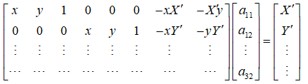
透视变换矩阵变换公式为:
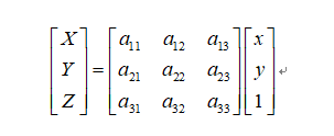
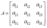
其中透视变换矩阵:
要移动的点,即源目标点为:

另外定点,即移动到的目标点为:

这是一个从二维空间变换到三维空间的转换,因为图像在二维平面,故除以Z, (X';Y';Z')表示图像上的点:
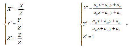
令
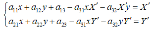
4个点可以得到8个方程,即可解出A。
下面代码是上面公式的具体实现,getPerspective()是根据4组点对获取的透视变换矩阵。
function perspective_mat = getPerspective(moving_points,fixed_points)
% GETPERSPECTIVE 根据点获取透视变换矩阵
% 输入:
%     moving_points:n*2点集坐标(x,y)
%     fixed_points:n*2点集坐标(x,y),点顺序要对应moving_points
% 输出:
%     perspective_mat:3*3透视变换矩阵
%
%  perspective_mat矩阵形式为[a11,a12,a13; a21,a22,a23; a31,a32,1];
%   满足fixed_points = perspective_mat*moving_points
% author: [email protected]
%

assert(size(moving_points,1) == size(fixed_points,1)&& ...
size(moving_points,1)>=4);

nums = size(moving_points,1);
coefficient_mat = zeros(2*nums,8);
b = zeros(2*nums,1);
for i = 1:nums
    currentPoint = moving_points(i,:);
    currentFixedPoint = fixed_points(i,:);
    coefficient_mat(2*i-1,:) = [currentPoint(1),currentPoint(2),1,...
        0,0,0,...
        -currentPoint(1)*currentFixedPoint(1),-currentFixedPoint(1)*currentPoint(2)];
    b(2*i-1) = currentFixedPoint(1);

    coefficient_mat(2*i,:) = [0,0,0,...
        currentPoint(1),currentPoint(2),1,...
        -currentPoint(1)*currentFixedPoint(2),-currentPoint(2)*currentFixedPoint(2)];
    b(2*i) = currentFixedPoint(2);
end
perspective_mat = coefficient_mat\b; % 大于4个点时候为最小二乘法计算
perspective_mat = reshape([perspective_mat;1],3,3)';
上面函数是通过4组点(大于等于)获取透视变换矩阵。下面给出测试代码,分别用手写的和系统的函数,对比时间加以说明。
%% prepare
img = rgb2gray(imread('book.jpg'));
width = size(img,2);
height = size(img,1);
figure;imshow(img)
% moving_points = [0,0;
%                 100,50;
%                 0,50;
%                 50,100];
moving_points = ginput(4);
hold on ; plot(moving_points(:,1),moving_points(:,2),'ro');
fixed_points = [0,0;
    100,0;
    0,200;
    100,200];

%% method 1,use matlab function
tfom = fitgeotrans(moving_points,fixed_points,'projective');
X = moving_points(:,1);
Y = moving_points(:,2);
[x,y] = transformPointsForward(tfom,X(:),Y(:));
figure;plot(x,y,'ro');title('验证坐标点对齐')
grid on
tic;
dst_img = imwarp(img,tfom);
t_sys = toc;
figure;imshow(dst_img);title(['图像仿射变换后(系统函数),耗时(s):',num2str(t_sys)])

%% method 2, get perspective matrix
perspective_mat = getPerspective(moving_points,fixed_points);
A = perspective_mat;
X = [1;width;1;width]; % 原图片的四个角点x坐标
Y = [1;1;height;height]; % 原图片的四个角点y坐标
moving_points_mat = [X(:)';Y(:)';ones(1,size(X(:),1))];
dst_points = A*moving_points_mat;
for i = 1:size(dst_points,2)
    dst_points(1:2,i) = dst_points(1:2,i)/dst_points(3,i);
end
figure;plot(dst_points(1,:),dst_points(2,:),'bo');title('原图像仿射变换后的坐标范围')
grid on;

%% 仿射变换后图像逐像素进行插值赋值
min_x = min(dst_points(1,:));
max_x = max(dst_points(1,:));
min_y = min(dst_points(2,:));
max_y = max(dst_points(2,:));
W = round(max_x - min_x);
H = round(max_y -min_y);
wrapImg = zeros(H,W);
tic;
for i = 1:H
    for j = 1:W
        x = min_x+j; % 使得x,y的范围在原坐标范围内
        y = min_y+i;
        moving_point = A\[x;y;1];
        temp_point = [moving_point(1);moving_point(2)]./moving_point(3);
        if temp_point(1)>=1&&temp_point(1)<width&& ...
                temp_point(2)>=1&&temp_point(2)<height
            wrapImg(i,j) = img(round(temp_point(2)),round(temp_point(1)));
        end
    end
end
t_manual = toc;
figure;
imshow(uint8(wrapImg));title(['图像仿射变换后(手写函数),耗时(s):',num2str(t_manual)])
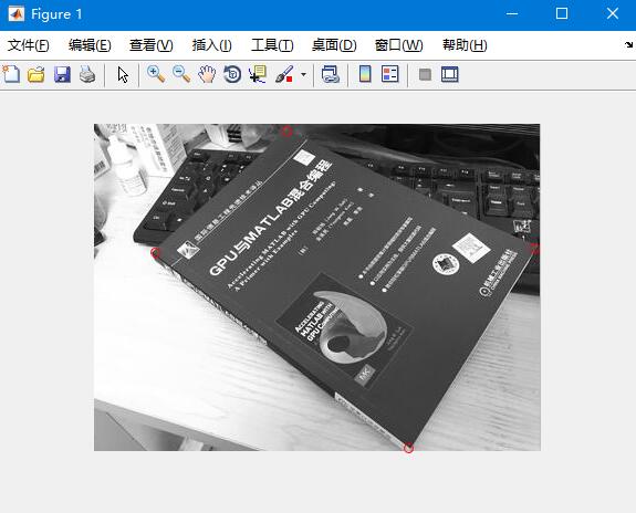
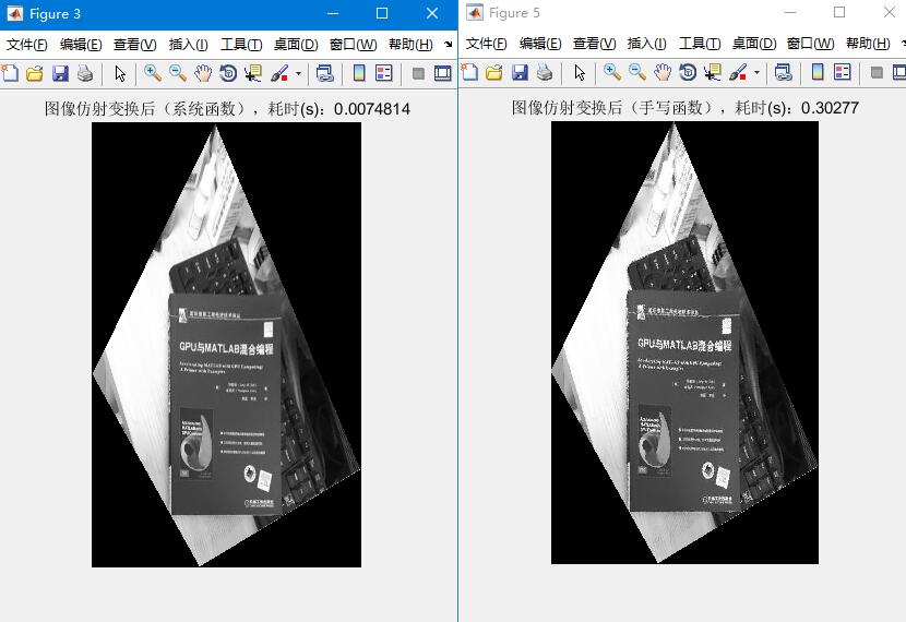
红色圆圈为鼠标点选的点,顺序为书籍左上点、右上点、左下点、右下点。图中对比可以看出,效果是一样的,不过系统的函数效率高,耗时较少。