前言
我们模拟了光照,发现真的很厉害,加上天空盒子,再加上反射感觉很逼真,但是看着看着你会发现。。不对,没影子。是的,光和影分不开的,有光的地方就会有影子,这才是真实的道理。怎么模拟影子呢?这就要用到前面学到的,帧缓冲-写入纹理。
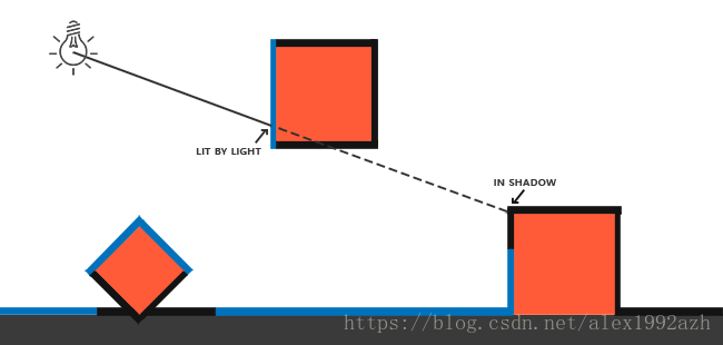
阴影产生的原因如图,就是因为同一条射线上里的光近的物体挡住了离的远的物体。
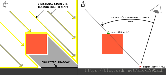
我们如何判断一个物体是否在阴影中呢?就是按照图上的,Z Distance也就是在光源方向上的空间来看的。这些Z表示深度,也就是距离光源的距离,如果我们从光源的透视图来渲染场景,并把深度值的结果储存到纹理中会怎样?通过这种方式,我们就能对光源的透视图所见的最近的深度值进行采样。最终,深度值就会显示从光源的透视图下见到的第一个片元了。我们管储存在纹理中的所有这些深度值,叫做深度贴图(depth map)或阴影贴图。
定向光产生的阴影
      // 1. Render depth of scene to texture (from light's perspective)
        // - Get light projection/view matrix.
        glCullFace(GL_FRONT);
        glm::mat4 lightProjection, lightView;
        glm::mat4 lightSpaceMatrix;
        GLfloat near_plane = 1.0f, far_plane = 7.5f;
//        lightProjection = glm::perspective(glm::radians(45.0f), (GLfloat)SHADOW_WIDTH / (GLfloat)SHADOW_HEIGHT, near_plane, far_plane);
        lightProjection = glm::ortho(-10.0f, 10.0f, -10.0f, 10.0f, near_plane, far_plane);
        lightView = glm::lookAt(lightPos, glm::vec3(0.0f), glm::vec3(0.0, 1.0, 0.0));
        lightSpaceMatrix = lightProjection * lightView;
        // - render scene from light's point of view
        simpleDepthShader.use();
        glUniformMatrix4fv(glGetUniformLocation(simpleDepthShader.ID, "lightSpaceMatrix"), 1, GL_FALSE, glm::value_ptr(lightSpaceMatrix));

        glViewport(0, 0, SHADOW_WIDTH, SHADOW_HEIGHT);
        glBindFramebuffer(GL_FRAMEBUFFER, depthMapFBO);
        glClear(GL_DEPTH_BUFFER_BIT);
        RenderScene(simpleDepthShader);
        glBindFramebuffer(GL_FRAMEBUFFER, 0);

        // Reset viewport
        glViewport(0, 0, SCR_WIDTH, SCR_HEIGHT);
        glClear(GL_COLOR_BUFFER_BIT | GL_DEPTH_BUFFER_BIT);
        glCullFace(GL_BACK);

        // 2. render scene as normal using the generated depth/shadow map
        // --------------------------------------------------------------
        glViewport(0, 0, SCR_WIDTH, SCR_HEIGHT);
        glClear(GL_COLOR_BUFFER_BIT | GL_DEPTH_BUFFER_BIT);
        shader.use();
        glm::mat4 projection = glm::perspective(glm::radians(camera.Zoom), (float)SCR_WIDTH / (float)SCR_HEIGHT, 0.1f, 100.0f);
        glm::mat4 view = camera.GetViewMatrix();
        shader.setMat4("projection", projection);
        shader.setMat4("view", view);
        // set light uniforms
        shader.setVec3("viewPos", camera.Position);
        shader.setVec3("lightPos", lightPos);
        shader.setMat4("lightSpaceMatrix", lightSpaceMatrix);
        glActiveTexture(GL_TEXTURE0);
        glBindTexture(GL_TEXTURE_2D, woodTexture);
        glActiveTexture(GL_TEXTURE1);
        glBindTexture(GL_TEXTURE_2D, depthMap);
        RenderScene(shader);

        // Render Depth map to quad
        debugDepthQuad.use();
        glUniform1f(glGetUniformLocation(debugDepthQuad.ID, "near_plane"), near_plane);
        glUniform1f(glGetUniformLocation(debugDepthQuad.ID, "far_plane"), far_plane);
        glActiveTexture(GL_TEXTURE0);
        glBindTexture(GL_TEXTURE_2D, depthMap);
//        RenderQuad(); 这是把那个深度贴图渲染出来的方法
看代码就知道了,步骤分为:
- 先从光源空间渲染一下场景,然后开一个帧缓冲,把渲染都写到纹理上
- 在视角空间按照以往的步骤渲染场景采样上面的深度图
glm::ortho 是因为是定向光
深度图
根据深度图的渲染场景
普通渲染场景中计算阴影的部分
float ShadowCalculation(vec4 fragPosLightSpace, float bias)
{
// perform perspective divide
vec3 projCoords = fragPosLightSpace.xyz / fragPosLightSpace.w;
// transform to [0,1] range
projCoords = projCoords * 0.5 + 0.5;
// get closest depth value from light's perspective (using [0,1] range fragPosLight as coords)
float closestDepth = texture(shadowMap, projCoords.xy).r;
// get depth of current fragment from light's perspective
float currentDepth = projCoords.z;
// check whether current frag pos is in shadow
// float shadow = currentDepth - bias > closestDepth ? 1.0 : 0.0; // use pcf not directly compare
// PCF
float shadow = 0.0;
vec2 texelSize = 1.0 / textureSize(shadowMap, 0);
for(int x = -1; x <= 1; ++x)
{
for(int y = -1; y <= 1; ++y)
{
float pcfDepth = texture(shadowMap, projCoords.xy + vec2(x, y) * texelSize).r;
shadow += currentDepth - bias > pcfDepth ? 1.0 : 0.0;
}
}
shadow /= 9.0;
if(projCoords.z > 1.0)
shadow = 0.0;
return shadow;
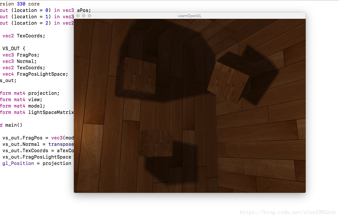
}void main()
{
vec3 color = texture(diffuseTexture, fs_in.TexCoords).rgb;
vec3 normal = normalize(fs_in.Normal);
vec3 lightColor = vec3(0.3);
// ambient
vec3 ambient = 0.3 * color;
// diffuse
vec3 lightDir = normalize(lightPos - fs_in.FragPos);
float diff = max(dot(lightDir, normal), 0.0);
vec3 diffuse = diff * lightColor;
// specular
vec3 viewDir = normalize(viewPos - fs_in.FragPos);
vec3 reflectDir = reflect(-lightDir, normal);
float spec = 0.0;
vec3 halfwayDir = normalize(lightDir + viewDir);
spec = pow(max(dot(normal, halfwayDir), 0.0), 64.0);
vec3 specular = spec * lightColor;
// calculate shadow
float bias = max(0.05 * (1.0 - dot(normal, lightDir)), 0.005);
float shadow = ShadowCalculation(fs_in.FragPosLightSpace, bias);
vec3 lighting = (ambient + (1.0 - shadow) * (diffuse + specular)) * color;
FragColor = vec4(lighting, 1.0);
}关于bias是为了解决阴影失真问题
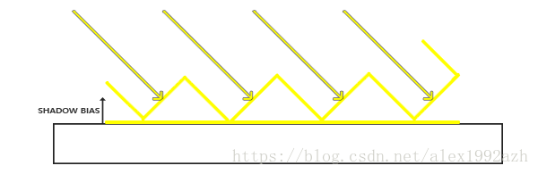
使用了偏移量后,所有采样点都获得了比表面深度更小的深度值,这样整个表面就正确地被照亮,没有任何阴影。
关于PCF就是为了让阴影更圆润
点光源
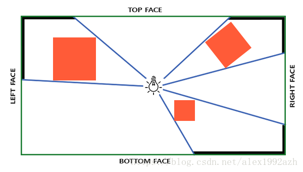
对于深度贴图,我们需要从一个点光源的所有渲染场景,普通2D深度贴图不能工作;如果我们使用立方体贴图会怎样?因为立方体贴图可以储存6个面的环境数据,它可以将整个场景渲染到立方体贴图的每个面上,把它们当作点光源四周的深度值来采样。
生成深度贴图的方式和前面的一样只不过换成了立方体贴图了
// 0. create depth cubemap transformation matrices
        // -----------------------------------------------
        float near_plane = 1.0f;
        float far_plane  = 25.0f;
        glm::mat4 shadowProj = glm::perspective(glm::radians(90.0f), (float)SHADOW_WIDTH / (float)SHADOW_HEIGHT, near_plane, far_plane);
        std::vector<glm::mat4> shadowTransforms;
        shadowTransforms.push_back(shadowProj * glm::lookAt(lightPos, lightPos + glm::vec3( 1.0f,  0.0f,  0.0f), glm::vec3(0.0f, -1.0f,  0.0f)));
        shadowTransforms.push_back(shadowProj * glm::lookAt(lightPos, lightPos + glm::vec3(-1.0f,  0.0f,  0.0f), glm::vec3(0.0f, -1.0f,  0.0f)));
        shadowTransforms.push_back(shadowProj * glm::lookAt(lightPos, lightPos + glm::vec3( 0.0f,  1.0f,  0.0f), glm::vec3(0.0f,  0.0f,  1.0f)));
        shadowTransforms.push_back(shadowProj * glm::lookAt(lightPos, lightPos + glm::vec3( 0.0f, -1.0f,  0.0f), glm::vec3(0.0f,  0.0f, -1.0f)));
        shadowTransforms.push_back(shadowProj * glm::lookAt(lightPos, lightPos + glm::vec3( 0.0f,  0.0f,  1.0f), glm::vec3(0.0f, -1.0f,  0.0f)));
        shadowTransforms.push_back(shadowProj * glm::lookAt(lightPos, lightPos + glm::vec3( 0.0f,  0.0f, -1.0f), glm::vec3(0.0f, -1.0f,  0.0f)));

        // 1. Render depth of scene to texture (from light's perspective)
        glViewport(0, 0, SHADOW_WIDTH, SHADOW_HEIGHT);
        glBindFramebuffer(GL_FRAMEBUFFER, depthMapFBO);
        glClear(GL_DEPTH_BUFFER_BIT);
        simpleDepthShader.use();
        for (unsigned int i = 0; i < 6; ++i)
            simpleDepthShader.setMat4("shadowMatrices[" + std::to_string(i) + "]", shadowTransforms[i]);
        simpleDepthShader.setFloat("far_plane", far_plane);
        simpleDepthShader.setVec3("lightPos", lightPos);
        RenderScene(simpleDepthShader);
        glBindFramebuffer(GL_FRAMEBUFFER, 0);

        // 2. render scene as normal using the generated depth/shadow map
        // --------------------------------------------------------------
        glViewport(0, 0, SCR_WIDTH, SCR_HEIGHT);
        glClear(GL_COLOR_BUFFER_BIT | GL_DEPTH_BUFFER_BIT);
        shader.use();
        glm::mat4 projection = glm::perspective(glm::radians(camera.Zoom), (float)SCR_WIDTH / (float)SCR_HEIGHT, 0.1f, 100.0f);
        glm::mat4 view = camera.GetViewMatrix();
        shader.setMat4("projection", projection);
        shader.setMat4("view", view);
        // set lighting uniforms
        shader.setVec3("lightPos", lightPos);
        shader.setVec3("viewPos", camera.Position);
        shader.setInt("shadows", shadows); // enable/disable shadows by pressing 'SPACE'
        shader.setFloat("far_plane", far_plane);
        glActiveTexture(GL_TEXTURE0);
        glBindTexture(GL_TEXTURE_2D, woodTexture);
        glActiveTexture(GL_TEXTURE1);
        glBindTexture(GL_TEXTURE_CUBE_MAP, depthCubemap);
        RenderScene(shader);
看代码 分为三个步骤:
0:创建立方体贴图矩阵 也就是从立方体的六个面的空间来着手
1: 渲染立方体深度贴图
2:从照相机空间也就是我们的视角空间渲染场景按照往常
相较平行光阴影shader最大的不同在于多了一个geometry-shader几何着色器
#version 330 core
layout (triangles) in;
layout (triangle_strip, max_vertices=18) out;

uniform mat4 shadowMatrices[6];

out vec4 FragPos; // FragPos from GS (output per emitvertex)

void main()
{
    for(int face = 0; face < 6; ++face)
    {
        gl_Layer = face; // built-in variable that specifies to which face we render.
        for(int i = 0; i < 3; ++i) // for each triangle's vertices
        {
            FragPos = gl_in[i].gl_Position;
            gl_Position = shadowMatrices[face] * FragPos;
            EmitVertex();
        }
        EndPrimitive();
    }
}
几何着色器有一个内建变量叫做gl_Layer,它指定发散出基本图形送到立方体贴图的哪个面。当不管它时,几何着色器就会像往常一样把它的基本图形发送到输送管道的下一阶段,但当我们更新这个变量就能控制每个基本图形将渲染到立方体贴图的哪一个面。当然这只有当我们有了一个附加到激活的帧缓冲的立方体贴图纹理才有效: