目录
1 机器人系统仿真的必要性与本篇学习目的
1.1 机器人系统仿真的必要性
对于ROS新手而言,可能会有疑问:学习机器人操作系统,实体机器人是必须的吗?答案是否定的,机器人一般价格不菲,为了降低机器人学习、调试成本,在ROS中提供了系统的机器人仿真实现,通过仿真,可以实现大部分需求,本章主要就是围绕“仿真”展开的,比如,本章会介绍:
- 如何创建并显示机器人模型;
- 如何搭建仿真环境;
- 如何实现机器人模型与仿真环境的交互。
本章预期的学习目标如下:
- 能够独立使用URDF创建机器人模型,并在Rviz和Gazebo中分别显示;
- 能够使用Gazebo搭建仿真环境;
- 能够使用机器人模型中的传感器(雷达、摄像头、编码器...)获取仿真环境数据。
1.2 一些概念
URDF是 Unified Robot Description Format 的首字母缩写,直译为统一(标准化)机器人描述格式,可以以一种 XML 的方式描述机器人的部分结构,比如底盘、摄像头、激光雷达、机械臂以及不同关节的自由度.....,该文件可以被 C++ 内置的解释器转换成可视化的机器人模型,是 ROS 中实现机器人仿真的重要组件
RViz 是 ROS Visualization Tool 的首字母缩写,直译为ROS的三维可视化工具。它的主要目的是以三维方式显示ROS消息,可以将 数据进行可视化表达。例如:可以显示机器人模型,可以无需编程就能表达激光测距仪(LRF)传感器中的传感 器到障碍物的距离,RealSense、Kinect或Xtion等三维距离传感器的点云数据(PCD, Point Cloud Data),从相机获取的图像值等
以“ros- [ROS_DISTRO] -desktop-full”命令安装ROS时,RViz会默认被安装。
运行使用命令
rviz或rosrun rviz rviz如果rviz没有安装,请调用如下命令自行安装:
sudo apt install ros-[ROS_DISTRO]-rvizGazebo是一款3D动态模拟器,用于显示机器人模型并创建仿真环境,能够在复杂的室内和室外环境中准确有效地模拟机器人。与游戏引擎提供高保真度的视觉模拟类似,Gazebo提供高保真度的物理模拟,其提供一整套传感器模型,以及对用户和程序非常友好的交互方式。
以“ros- [ROS_DISTRO] -desktop-full”命令安装ROS时,gzebo会默认被安装。
2 URDF 集成 RVIZ 基本流程
URDF 不能单独使用,需要结合 Rviz 或 Gazebo,URDF 只是一个文件,需要在 Rviz 或 Gazebo 中渲染成图形化的机器人模型,当前,首先演示URDF与Rviz的集成使用,因为URDF与Rviz的集成较之于URDF与Gazebo的集成更为简单,后期,基于Rviz的集成实现,我们再进一步介绍URDF语法。
我们需要建立一个盒型机器人并在RVIZ中显示:
实现流程:
准备:新建功能包,导入依赖
核心:编写 urdf 文件
核心:在 launch 文件集成 URDF 与 Rviz
在 Rviz 中显示机器人模型
第一步:新建功能包 依赖于urdf与xacro
cmake_minimum_required(VERSION 2.8.3)
project(test)

######################
### Cmake flags
######################
set(CMAKE_BUILD_TYPE "Release")
set(CMAKE_CXX_FLAGS "-std=c++11")
set(CMAKE_CXX_FLAGS_RELEASE "-O3 -Wall -g -pthread")

find_package(catkin REQUIRED COMPONENTS
    roscpp
    rospy
    roslib
    # msg
    urdf
    xacro
)

catkin_package()

include_directories(${catkin_INCLUDE_DIRS})
第二步:编写urdf文件(测试)
<robot name="mycar">
    <link name="base_link">
        <visual>
            <geometry>
                <box size="0.5 0.2 0.1" />
            </geometry>
        </visual>
    </link>
</robot>
第三步:在 launch 文件中集成 URDF 与 Rviz
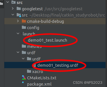
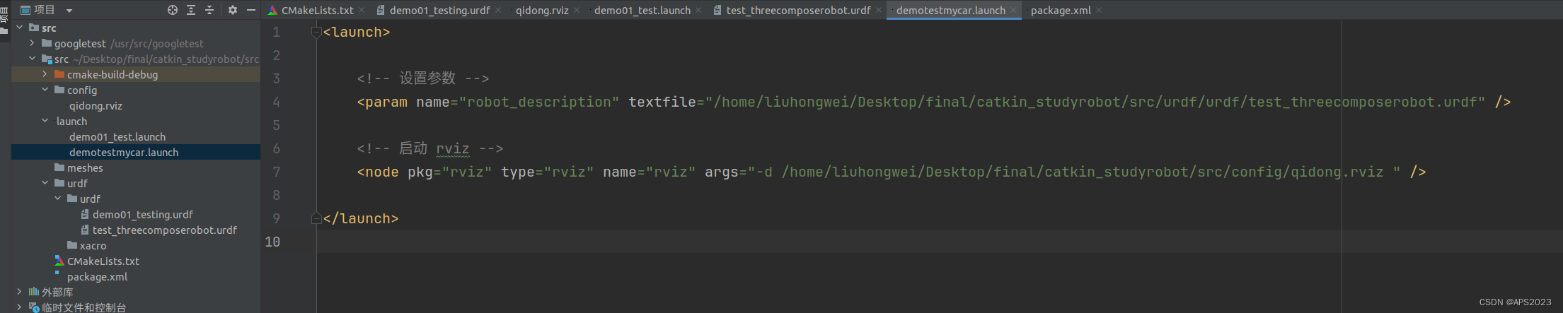
<launch>

    <!-- 设置参数 -->
    <param name="robot_description" textfile="/home/liuhongwei/Desktop/final/catkin_studyrobot/src/urdf/urdf/demo01_testing.urdf" />

    <!-- 启动 rviz -->
    <node pkg="rviz" type="rviz" name="rviz" />

</launch>
我的目录结构如下:
我们启动launch文件:
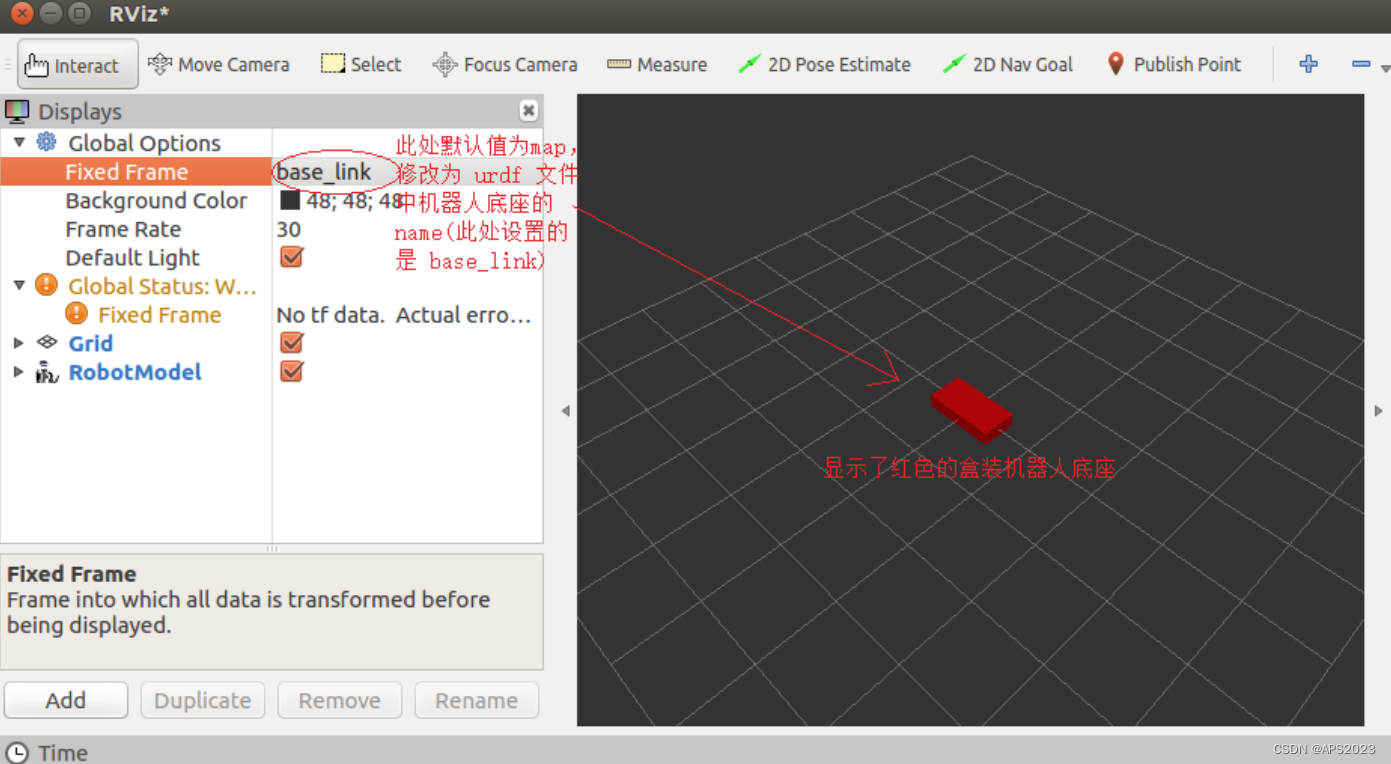
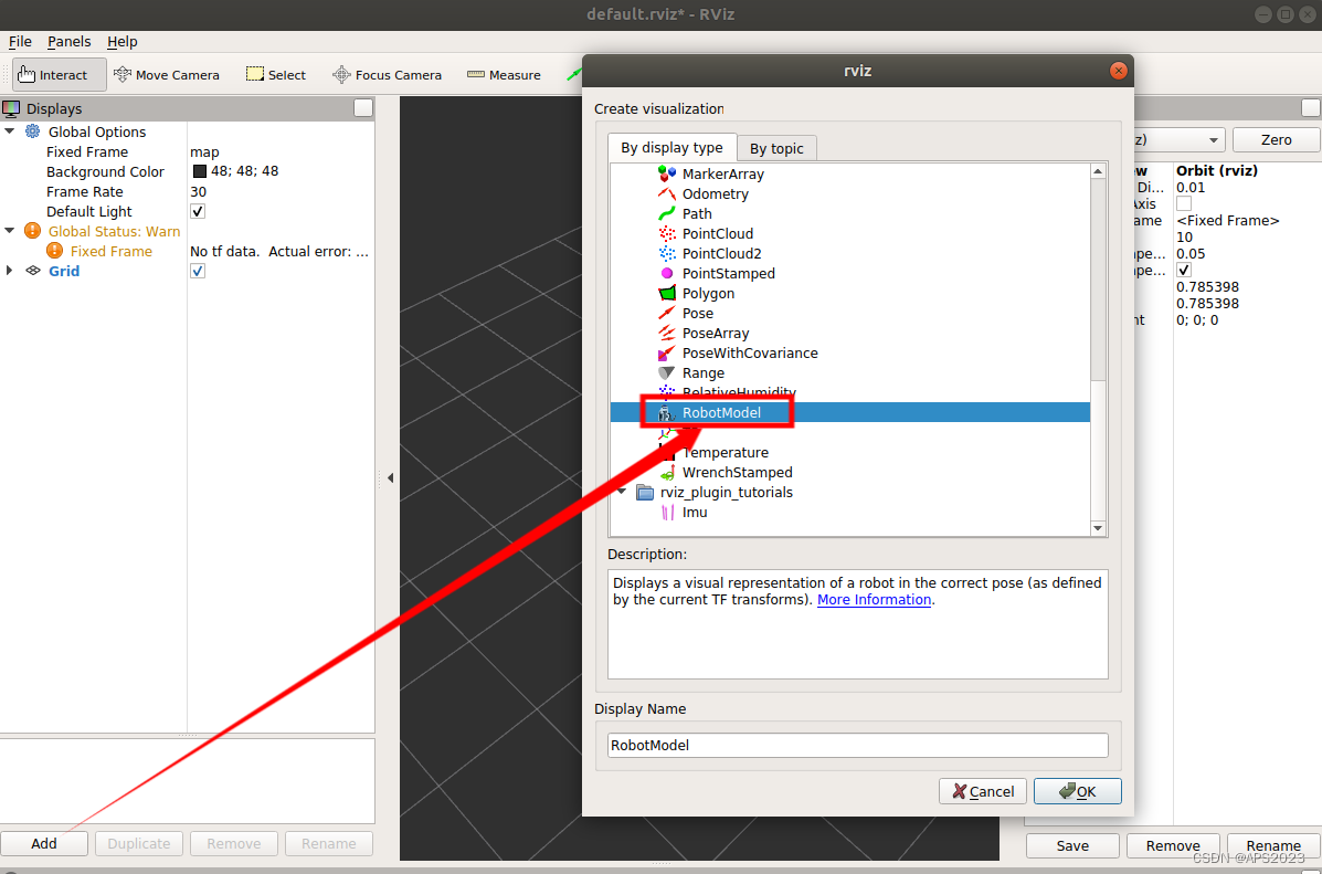
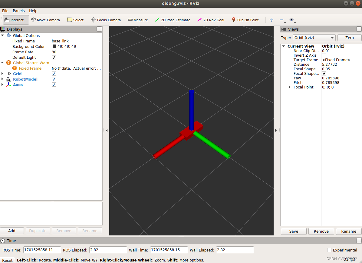
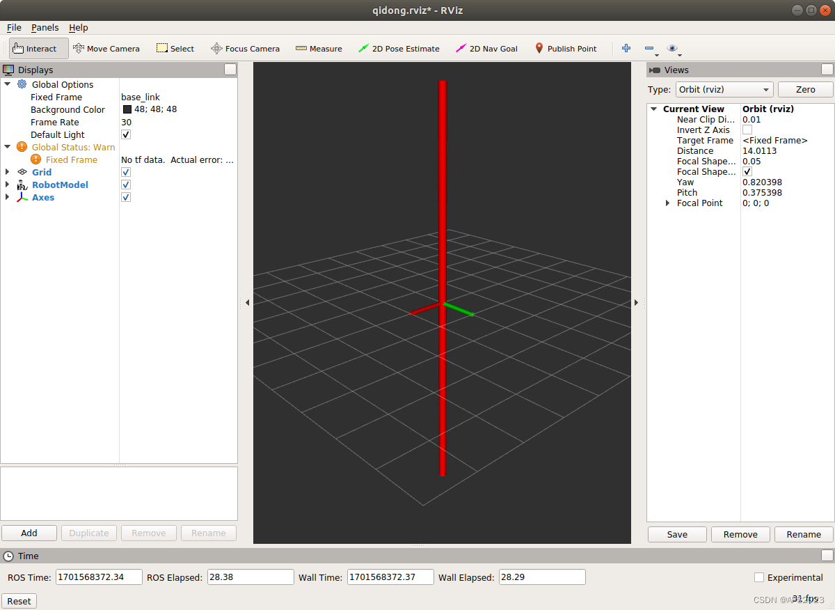
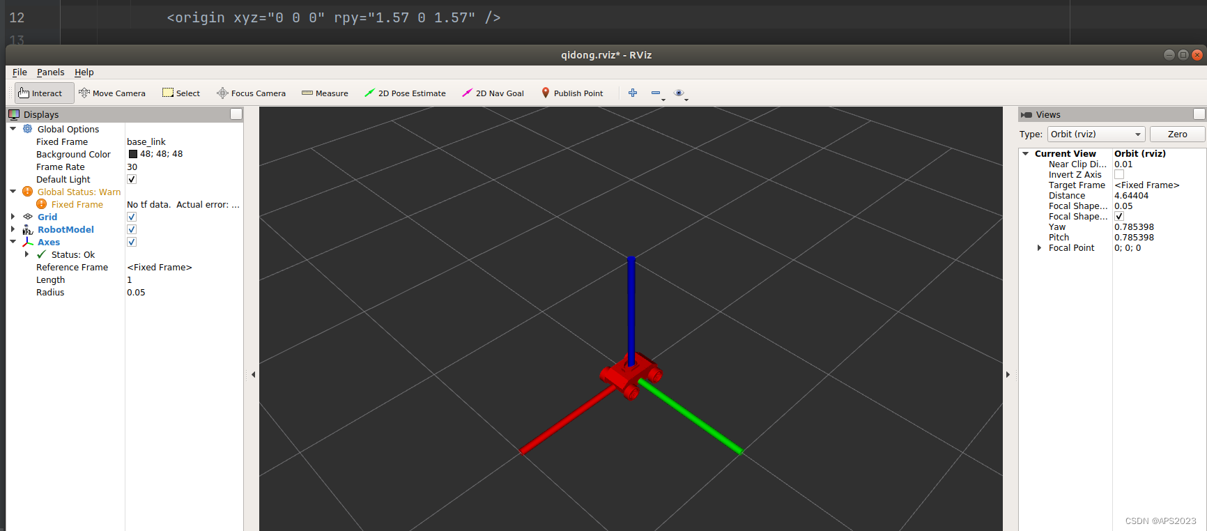
liuhongwei@liuhongwei-Legion-Y9000P-IRX8H:~/Desktop/final/catkin_studyrobot$ source devel/setup.bash
liuhongwei@liuhongwei-Legion-Y9000P-IRX8H:~/Desktop/final/catkin_studyrobot$ roslaunch test demo01_test.launch
发现Rviz啥也没有....,需要配置一下:
在Rviz中添加机器人模型:
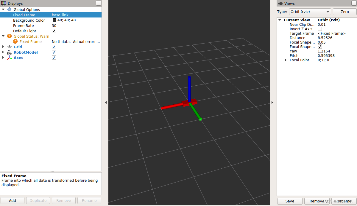
改正参考坐标系:base_link
机器人完全被导入了。
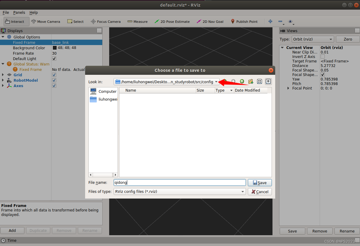
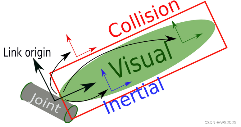
那么我们每次都要这么设置太麻烦了,我们在Rviz中保存设置:
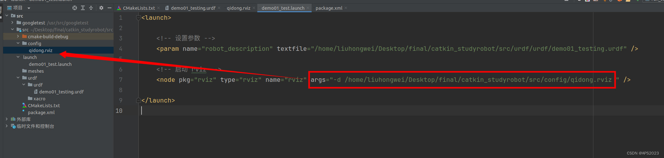
我们修改launch文件,让读取的时候载入我们的设置。
<launch>

    <!-- 设置参数 -->
    <param name="robot_description" textfile="/home/liuhongwei/Desktop/final/catkin_studyrobot/src/urdf/urdf/demo01_testing.urdf" />

    <!-- 启动 rviz -->
    <node pkg="rviz" type="rviz" name="rviz" args="-d /home/liuhongwei/Desktop/final/catkin_studyrobot/src/config/qidong.rviz " />

</launch>
再次打开就是直接这个界面啦~

2.1 urdf语法
URDF 文件是一个标准的 XML 文件,在 ROS 中预定义了一系列的标签用于描述机器人模型,机器人模型可能较为复杂,但是 ROS 的 URDF 中机器人的组成却是较为简单,可以主要简化为两部分:连杆(link标签) 与 关节(joint标签),接下来我们就通过案例了解一下 URDF 中的不同标签:
- robot 根标签,类似于 launch文件中的launch标签
- link 连杆标签
- joint 关节标签
- gazebo 集成gazebo需要使用的标签
关于gazebo标签,后期在使用 gazebo 仿真时,才需要使用到,用于配置仿真环境所需参数,比如: 机器人材料属性、gazebo插件等,但是该标签不是机器人模型必须的,只有在仿真时才需设置
2.1.1 robot标签
urdf 中为了保证 xml 语法的完整性,使用了
robot标签作为根标签,所有的 link 和 joint 以及其他标签都必须包含在 robot 标签内,在该标签内可以通过 name 属性设置机器人模型的名称1.属性
name: 指定机器人模型的名称
2.子标签
其他标签都是子级标签
2.1.2 link标签
urdf 中的 link 标签用于描述机器人某个部件(也即刚体部分)的外观和物理属性,比如: 机器人底座、轮子、激光雷达、摄像头...每一个部件都对应一个 link, 在 link 标签内,可以设计该部件的形状、尺寸、颜色、惯性矩阵、碰撞参数等一系列属性。
1.属性
- name ---> 为连杆命名
2.子标签
visual ---> 描述外观(对应的数据是可视的)
geometry 设置连杆的形状
标签1: box(盒状)
- 属性:size=长(x) 宽(y) 高(z)
标签2: cylinder(圆柱)
- 属性:radius=半径 length=高度
标签3: sphere(球体)
- 属性:radius=半径
标签4: mesh(为连杆添加皮肤)
- 属性: filename=资源路径(格式:package://<packagename>/<path>/文件)
origin 设置偏移量与倾斜弧度
属性1: xyz=x偏移 y便宜 z偏移
属性2: rpy=x翻滚 y俯仰 z偏航 (单位是弧度)
metrial 设置材料属性(颜色)
属性: name
标签: color
- 属性: rgba=红绿蓝权重值与透明度 (每个权重值以及透明度取值[0,1])
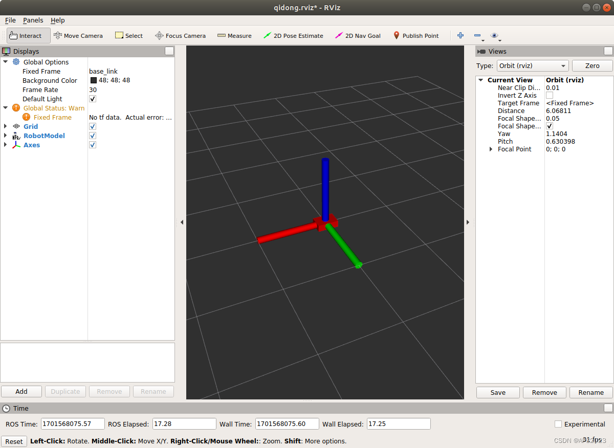
collision ---> 连杆的碰撞属性
Inertial ---> 连杆的惯性矩阵
在此,只演示
visual使用。3.一个案例
分别生成长方体、圆柱与球体的机器人部件
先生成立方体,用我们之前的rviz配置:
<robot name = "mycar">

    <link name="base_link">
        <visual>
            <geometry>
                <box size="0.3 0.2 0.1" />
            </geometry>

        </visual>
    </link>

</robot>
launch文件还是和前面一样。
生成圆柱:
<robot name = "mycar">

    <link name="base_link">
        <visual>
            <geometry>
                <!-- <box size="0.3 0.2 0.1" />  -->

                <cylinder radius="0.1" length="10" />
            </geometry>

        </visual>
    </link>

</robot>
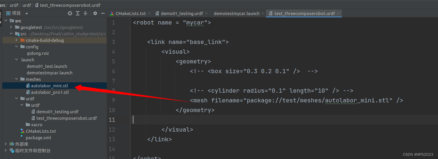
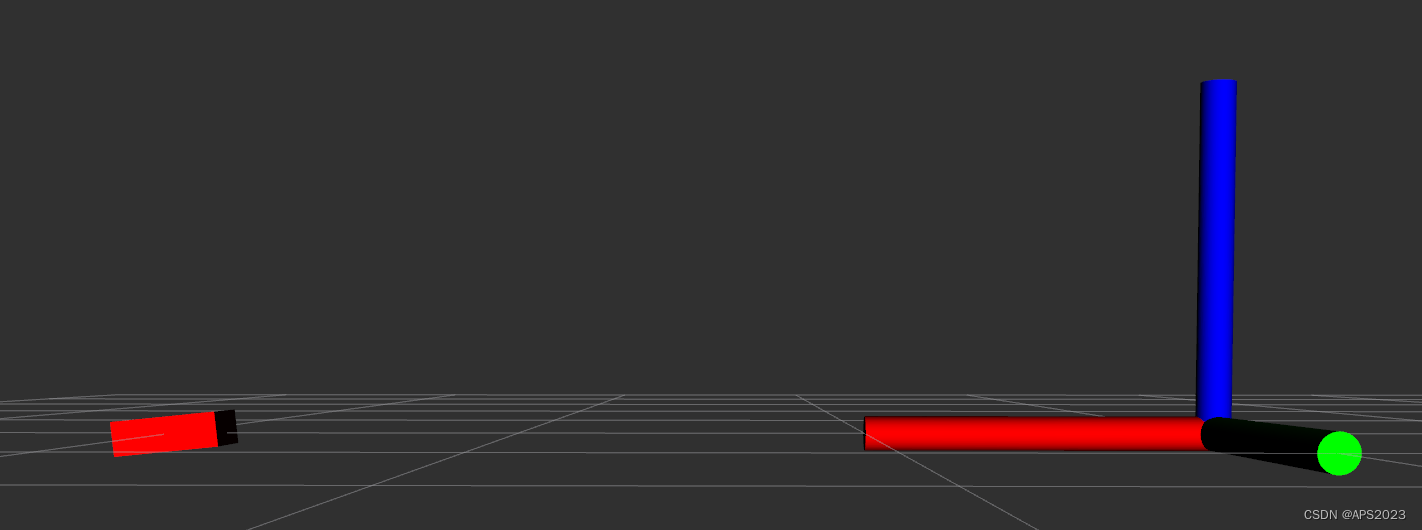
mesh标签可以将外部的模型导入:
其中,package是功能包的名字。后面是相对于ros工作目录的相对路径,我们执行一下。
成功导入了。
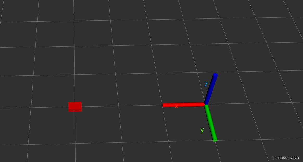
这个机器人是歪的,如何摆正呢?我们先拿立方体举例子:
origin 设置偏移量与倾斜弧度
属性1: xyz=x偏移 y便宜 z偏移
属性2: rpy=x翻滚 y俯仰 z偏航 (单位是弧度)
<robot name = "mycar">

    <link name="base_link">
        <visual>
            <geometry>
                <box size="0.3 0.2 0.1" />

                <!-- <cylinder radius="0.1" length="10" /> -->
                <!-- <mesh filename="package://test/meshes/autolabor_mini.stl" />  -->
            </geometry>

            <origin xyz="3 0 0" rpy="0 0 0" />

        </visual>
    </link>

</robot>
RPY呢,感受一下:先改变R。沿着X轴翻转。
P呢?
沿Y轴进行了运动。Yaw当然是Z轴的旋转啦。
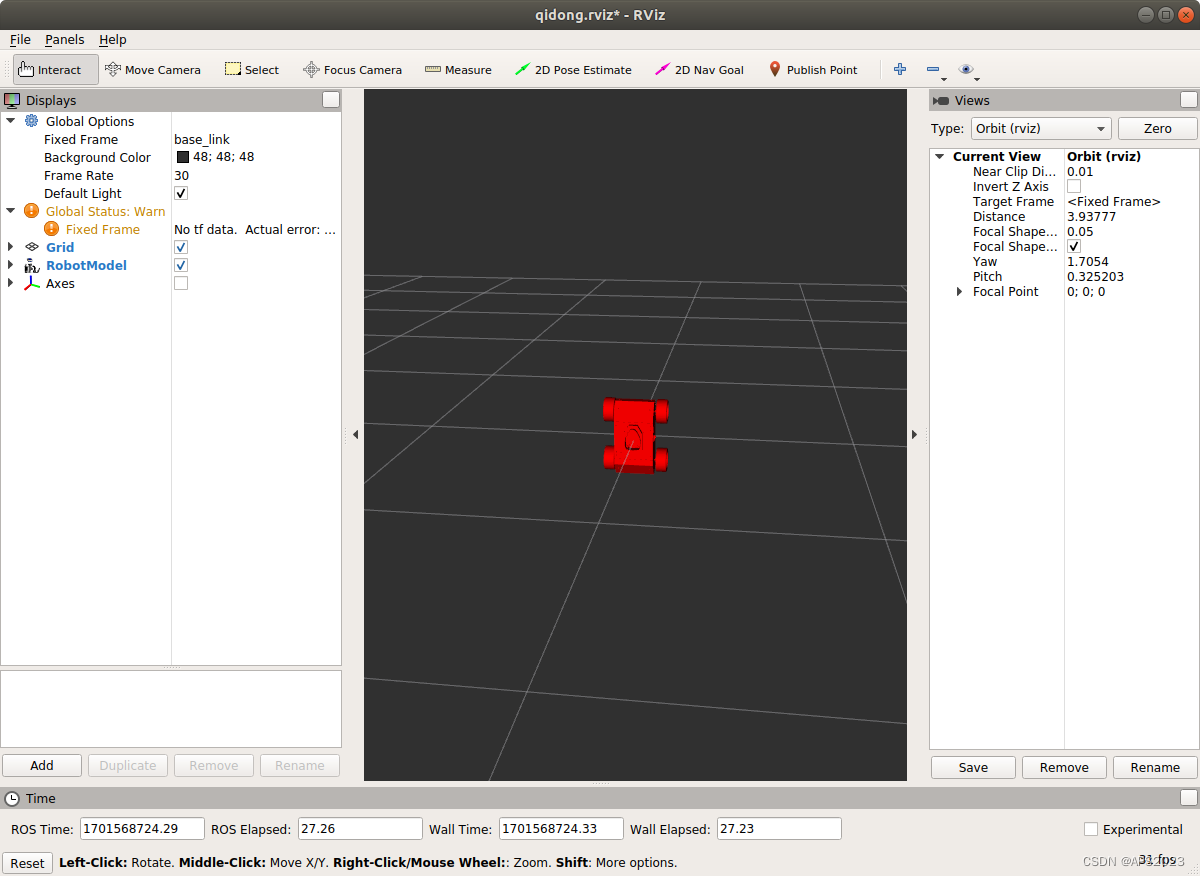
了解这些后,我们看看我们的小车。怎么将它摆正呢?
沿着x轴旋转90度是不是就可以了。
<robot name = "mycar">

    <link name="base_link">
        <visual>
            <geometry>
                <! -- <box size="0.3 0.2 0.1" /> -->

                <!-- <cylinder radius="0.1" length="10" /> -->
                <mesh filename="package://test/meshes/autolabor_mini.stl" />
            </geometry>

            <origin xyz="0 0 0" rpy="1.57 0 0" />

        </visual>
    </link>

</robot>
那我还想让他摆向X轴正方向呢?沿Z轴转改变偏航角就ok啦!
我想换个颜色呢??
metrial 设置材料属性(颜色)
属性: name
标签: color
<robot name = "mycar">

    <link name="base_link">
        <visual>
            <geometry>
                <! -- <box size="0.3 0.2 0.1" /> -->

                <!-- <cylinder radius="0.1" length="10" /> -->
                <mesh filename="package://test/meshes/autolabor_mini.stl" />
            </geometry>

            <origin xyz="0 0 0" rpy="1.57 0 1.57" />
            <material name="car_color">
                <color rgba="0 0 1 1" />
            </material>
        </visual>
    </link>

</robot>
变成蓝色~


2.1.3 joint标签
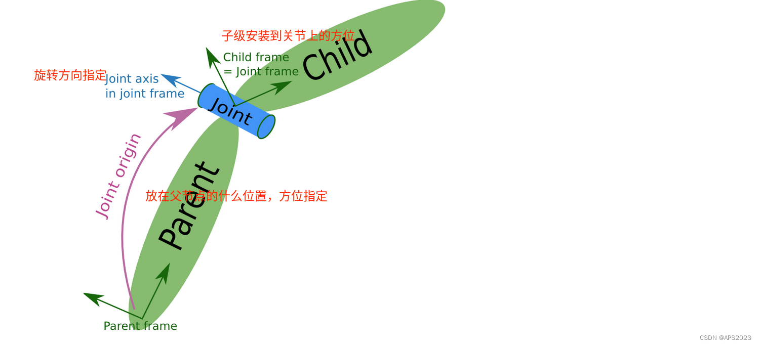
urdf 中的 joint 标签用于描述机器人关节的运动学和动力学属性,还可以指定关节运动的安全极限,机器人的两个部件(分别称之为 parent link 与 child link)以"关节"的形式相连接,不同的关节有不同的运动形式: 旋转、滑动、固定、旋转速度、旋转角度限制....,
比如:安装在底座上的轮子可以360度旋转,而摄像头则可能是完全固定在底座上。
joint标签对应的数据在模型中是不可见的。
父级和子级和物理实现的运动关系有关。
1.属性
name ---> 为关节命名
type ---> 关节运动形式
continuous: 旋转关节,可以绕单轴无限旋转
revolute: 旋转关节,类似于 continues,但是有旋转角度限制
prismatic: 滑动关节,沿某一轴线移动的关节,有位置极限
planer: 平面关节,允许在平面正交方向上平移或旋转
floating: 浮动关节,允许进行平移、旋转运动
fixed: 固定关节,不允许运动的特殊关节
2.子标签
parent(必需的)
parent link的名字是一个强制的属性:
- link:父级连杆的名字,是这个link在机器人结构树中的名字。
child(必需的)
child link的名字是一个强制的属性:
- link:子级连杆的名字,是这个link在机器人结构树中的名字。
origin
- 属性: xyz=各轴线上的偏移量 rpy=各轴线上的偏移弧度。(joint添加到parent的哪个位置)
axis
- 属性: xyz用于设置围绕哪个关节轴运动。
3.案例实现
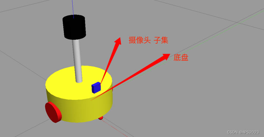
创建机器人模型,底盘为长方体,在长方体的前面添加一摄像头,摄像头可以沿着 Z 轴 360 度旋转。
我们设置摄像头还有小车底盘信息:
<!--
    需求: 创建机器人模型,底盘为长方体,
         在长方体的前面添加一摄像头,
         摄像头可以沿着 Z 轴 360 度旋转

 -->
<robot name="mycar">
    <!-- 底盘 -->
    <link name="base_link">
        <visual>
            <geometry>
                <box size="0.5 0.2 0.1" />
            </geometry>
            <origin xyz="0 0 0" rpy="0 0 0" />
            <material name="blue">
                <color rgba="0 0 1.0 0.5" />
            </material>
        </visual>
    </link>

    <!-- 摄像头 -->
    <link name="camera">
        <visual>
            <geometry>
                <box size="0.02 0.05 0.05" />
            </geometry>
            <origin xyz="0 0 0" rpy="0 0 0" />
            <material name="red">
                <color rgba="1 0 0 0.5" />
            </material>
        </visual>
    </link>


</robot>
再设置关节信息,我们假设摄像头可以360度旋转,类型是continuous。
我们设置子节点、父节点:
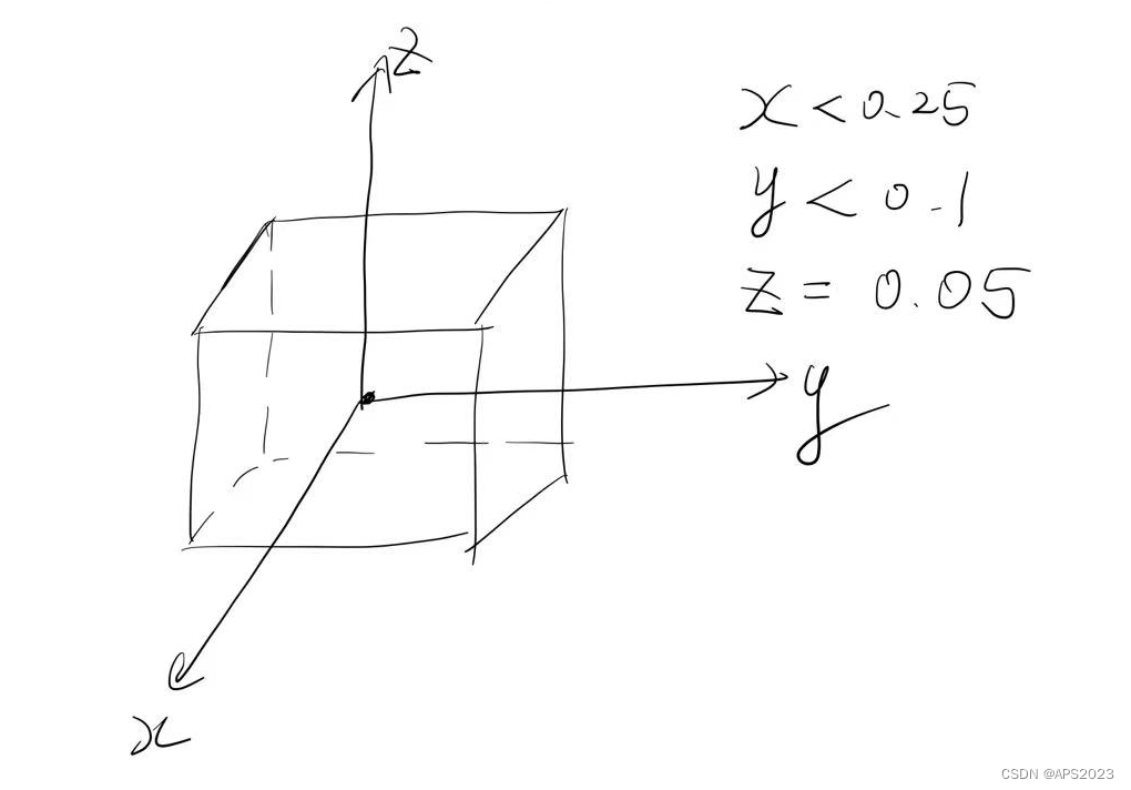
<parent link="base_link" />
<child link="camera" />
现在计算一下偏移,我们画个图:
因为摄像头只能绕Z轴转,axis要设置为1。
<!--
    需求: 创建机器人模型,底盘为长方体,
         在长方体的前面添加一摄像头,
         摄像头可以沿着 Z 轴 360 度旋转

 -->
<robot name="mycar">
    <!-- 底盘 -->
    <link name="base_link">
        <visual>
            <geometry>
                <box size="0.5 0.2 0.1" />
            </geometry>
            <origin xyz="0 0 0" rpy="0 0 0" />
            <material name="blue">
                <color rgba="0 0 1.0 0.5" />
            </material>
        </visual>
    </link>

    <!-- 摄像头 -->
    <link name="camera">
        <visual>
            <geometry>
                <box size="0.02 0.05 0.05" />
            </geometry>
            <origin xyz="0 0 0" rpy="0 0 0" />
            <material name="red">
                <color rgba="1 0 0 0.5" />
            </material>
        </visual>
    </link>

    <!-- 关节 -->
    <joint name="camera2baselink" type="continuous">
        <parent link="base_link" />
        <child link="camera" />
        <!-- 需要计算两个 link 的物理中心之间的偏移量 -->
        <origin xyz="0.2 0 0.075" rpy="0 0 0" />
        <axis xyz="0 0 1" />
    </joint>

</robot>
写launch文件:
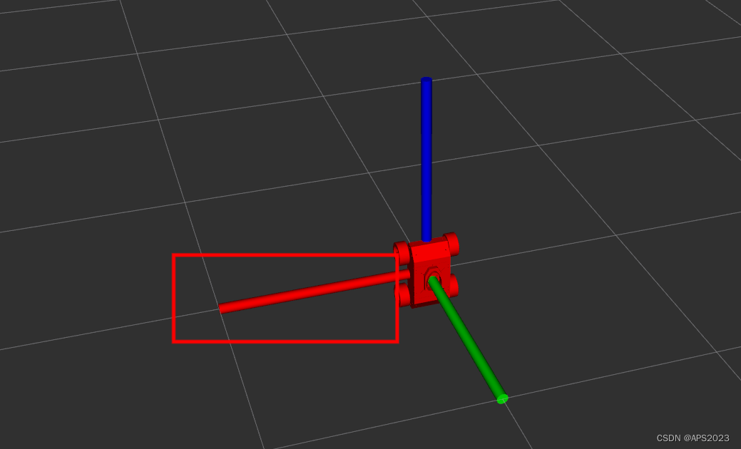
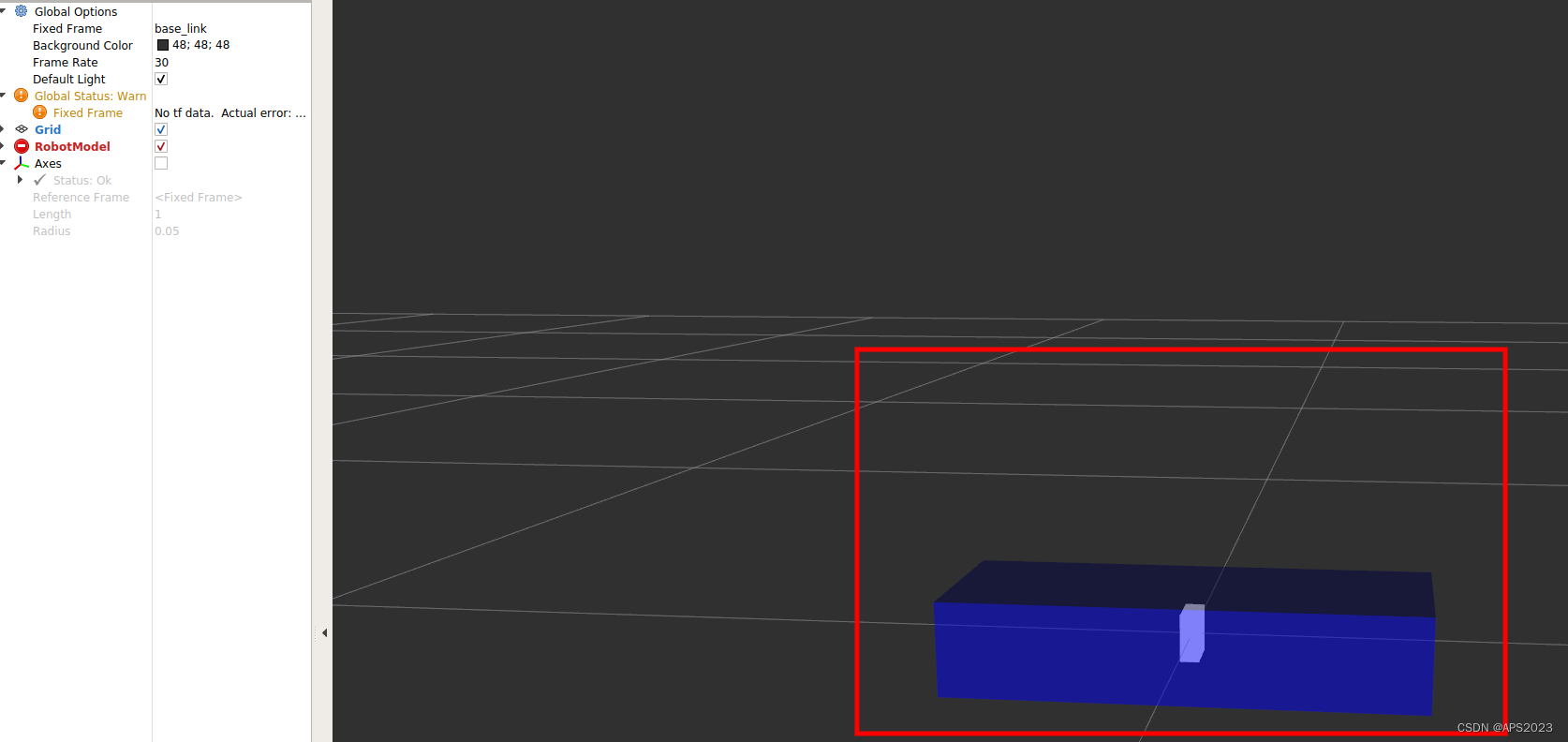
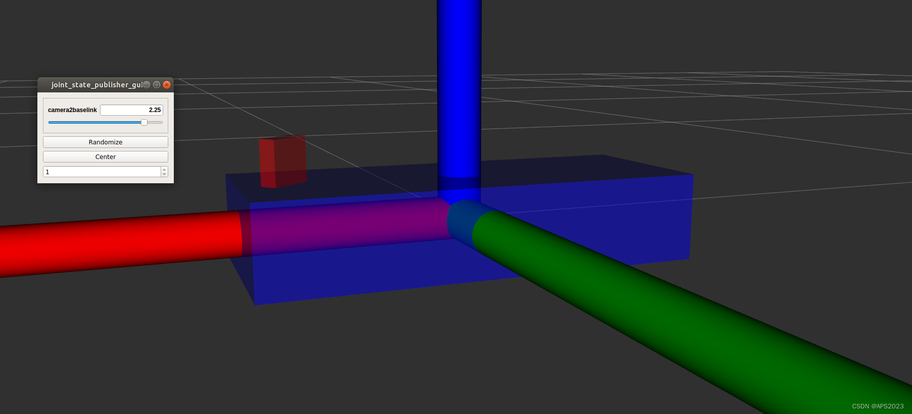
<launch>

    <!-- 设置参数 -->
    <param name="robot_description" textfile="/home/liuhongwei/Desktop/final/catkin_studyrobot/src/urdf/urdf/test_threecomposerobot.urdf" />

    <!-- 启动 rviz -->
    <node pkg="rviz" type="rviz" name="rviz" args="-d /home/liuhongwei/Desktop/final/catkin_studyrobot/src/config/qidong.rviz " />

</launch>
运行:发现有问题,摄像头应该是在我的车子上,怎么这样了?颜色也不对。
存在问题:摄像头显示位置不对,没有cam到base_link的TF
原因是rviz显示urdf的时候必须发布不同不同部件间的坐标系关系
解决:ROS提供了关于机器人模型显示的坐标发表相关节点。
完整的launch文件:
<launch>

    <!-- 设置参数 -->
    <param name="robot_description" textfile="/home/liuhongwei/Desktop/final/catkin_studyrobot/src/urdf/urdf/demo03_cam_robot.urdf" />

    <!-- 启动 rviz -->
    <node pkg="rviz" type="rviz" name="rviz" args="-d /home/liuhongwei/Desktop/final/catkin_studyrobot/src/config/qidong.rviz " />
    <!-- 添加关节状态发布节点 -->
    <node pkg="joint_state_publisher" type="joint_state_publisher" name="joint_state_publisher" />
    <!-- 添加机器人状态发布节点 -->
    <node pkg="robot_state_publisher" type="robot_state_publisher" name="robot_state_publisher" />
    <!-- 可选:用于控制关节运动的节点 -->
    <node pkg="joint_state_publisher_gui" type="joint_state_publisher_gui" name="joint_state_publisher_gui" />
</launch>
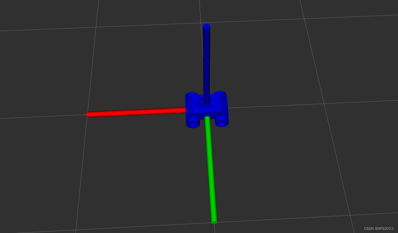
发现嵌入了。。。。
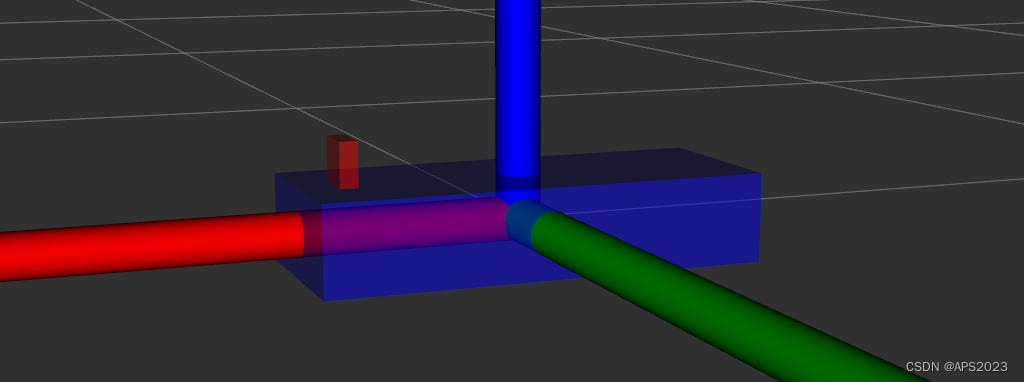
这是因为关节Z轴的偏移量是0.05,那么关节点刚好在上面平面上。因为关节点和相机的中心点是重合的。需要让中心点上移半个cam的高度。0.05 + 1/2 0.05/2 = 0.075
    <joint name="camera2baselink" type="continuous">
        <parent link="base_link" />
        <child link="camera" />
        <origin xyz="0.2 0 0.05" rpy="0 0 0" />
        <axis xyz="0 0 1" />
    </joint>
显示正常啦!
旋转一下哈哈。


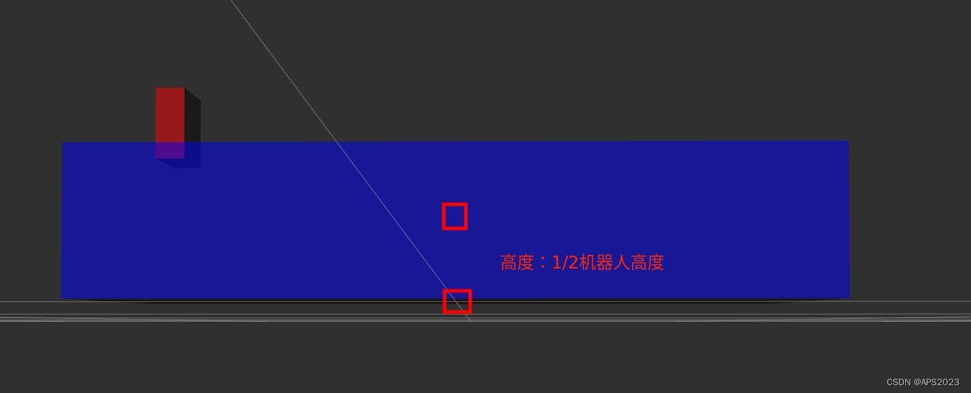
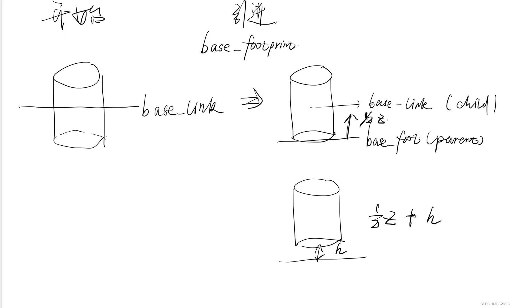
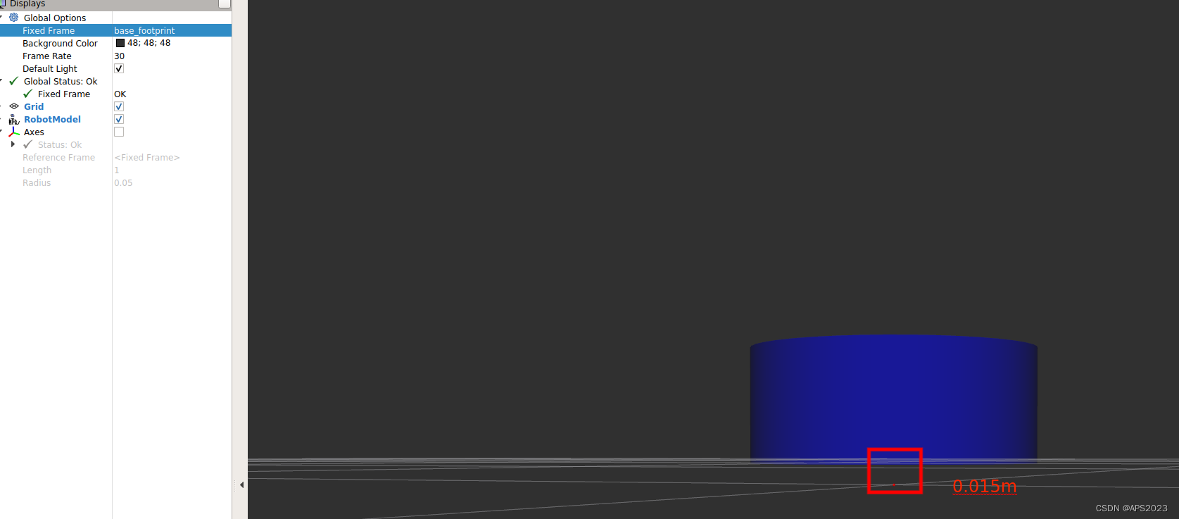
2.1.4 设置base_footprint优化urdf
前面实现的机器人模型是半沉到地下的,因为默认情况下: 底盘的中心点位于地图原点上,所以会导致这种情况产生,可以使用的优化策略,将初始 link 设置为一个尺寸极小的 link(比如半径为 0.001m 的球体,或边长为 0.001m 的立方体),然后再在初始 link 上添加底盘等刚体,这样实现,虽然仍然存在初始link半沉的现象,但是基本可以忽略了。这个初始 link 一般称之为 base_footprint。
先设置一个极小的base_footprint
    <link name="base_footprint">
        <visual>
            <geometry>
                <box size="0.001 0.001 0.001" />
            </geometry>
        </visual>
    </link>
关联base_link与base_footprint:base_link到base_footprintZ轴增加了0.05米
    <joint name="link2footprint" type="fixed">
        <parent link="base_footprint" />
        <child link="base_link" />
        <origin xyz="0 0 0.05" rpy="0 0 0" />
        <axis xyz="0 0 0" />
    </joint>
启动launch看看效果。
2.1.5 可能问题
问题:UnicodeEncodeError: 'ascii' codec can't encode characters in position 463-464: ordinal not in range(128)
[joint_state_publisher-3] process has died [pid 4443, exit code 1, cmd /opt/ros/melodic/lib/joint_state_publisher/joint_state_publisher __name:=joint_state_publisher __log:=/home/rosmelodic/.ros/log/b38967c0-0acb-11eb-aee3-0800278ee10c/joint_state_publisher-3.log].
log file: /home/rosmelodic/.ros/log/b38967c0-0acb-11eb-aee3-0800278ee10c/joint_state_publisher-3*.log解决:去除urdf中文注释
问题:[ERROR] [1584370263.037038]: Could not find the GUI, install the 'joint_state_publisher_gui' package
解决:
sudo apt install ros-melodic-joint-state-publisher-gui
2.2 案例:设计机器人
2.2.1 需求
创建一个四轮圆柱状机器人模型,机器人参数如下,底盘为圆柱状,半径 10cm,高 8cm,四轮由两个驱动轮和两个万向支撑轮组成,两个驱动轮半径为 3.25cm,轮胎宽度1.5cm,两个万向轮为球状,半径 0.75cm,底盘离地间距为 1.5cm(与万向轮直径一致)。
实现流程:
创建机器人模型可以分步骤实现
新建 urdf 文件,并与 launch 文件集成
搭建底盘
在底盘上添加两个驱动轮
在底盘上添加两个万向轮
2.2.2 添加base_footprint
    <link name="base_footprint">
        <visual>
            <geometry>
                <sphere radius="0.001" />
            </geometry>
        </visual>
    </link>
2.2.3 添加底盘
参数
形状:圆柱
半径:10 cm
高度:8 cm
离地:1.5 cm我们先不设置偏移量:
    <link name="base_link">
        <visual>
            <geometry>
                <cylinder radius="0.1" length="0.08" />
            </geometry>
            <origin xyz="0 0 0" rpy="0 0 0" />
            <material name="blue">
                <color rgba="0 0 1.0 0.5" />
            </material>
        </visual>
    </link>
添加baselink到basefootprint的关节:
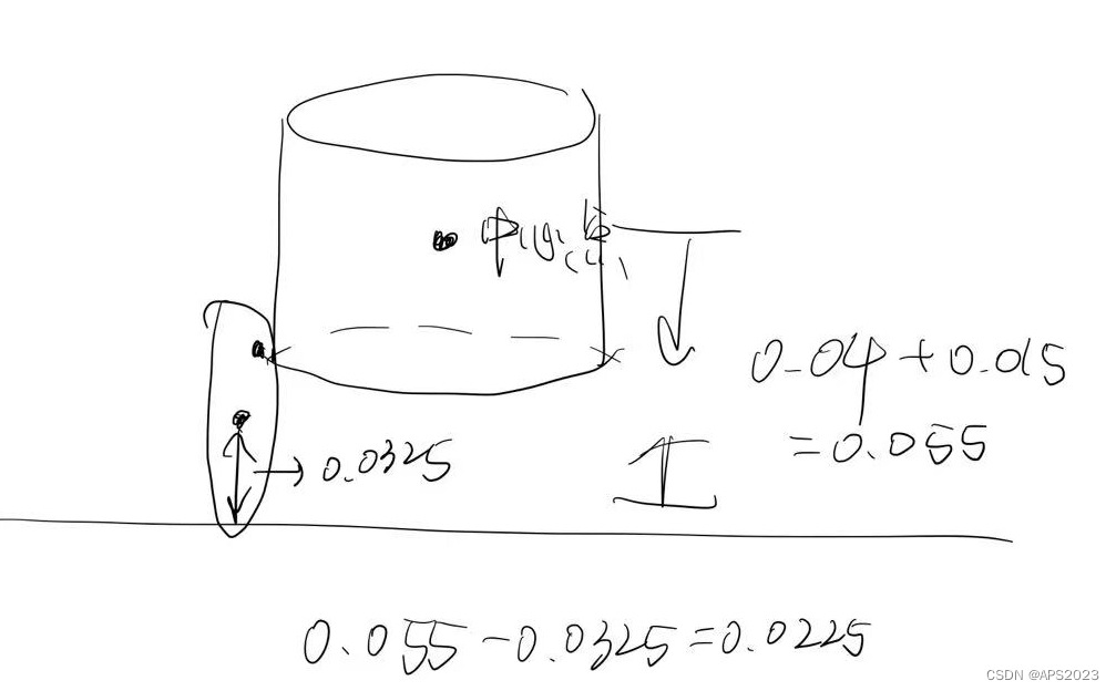
    <joint name="base_link2base_footprint" type="fixed">
        <parent link="base_footprint" />
        <child link="base_link"/>
        <origin xyz="0 0 0.055" />
    </joint>
原来parent link到child link只需要变化一个1/2的底盘高,也就是0.04米。但是又要离地1.5cm,即0.015m,那就是0.055米。
我们现在启动节点:
满足需求。
2.2.4 驱动轮添加
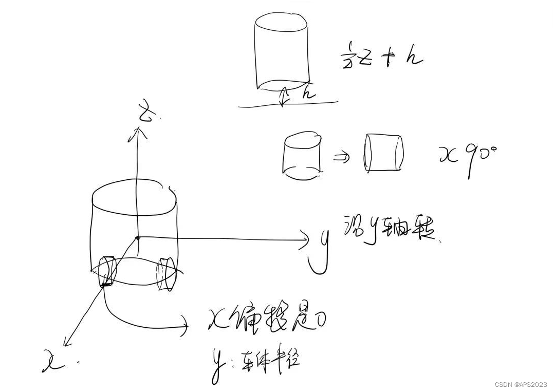
驱动轮是侧翻的圆柱
参数
半径: 3.25 cm
长度: 1.5 cm
颜色: 黑色
关节设置:
x = 0
y = 底盘的半径 + 轮胎宽度 / 2
z = 离地间距 + 底盘长度 / 2 - 轮胎半径 = 1.5 + 4 - 3.25 = 2.25(cm)
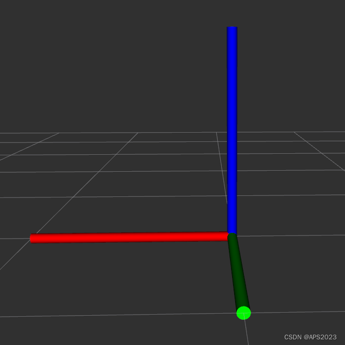
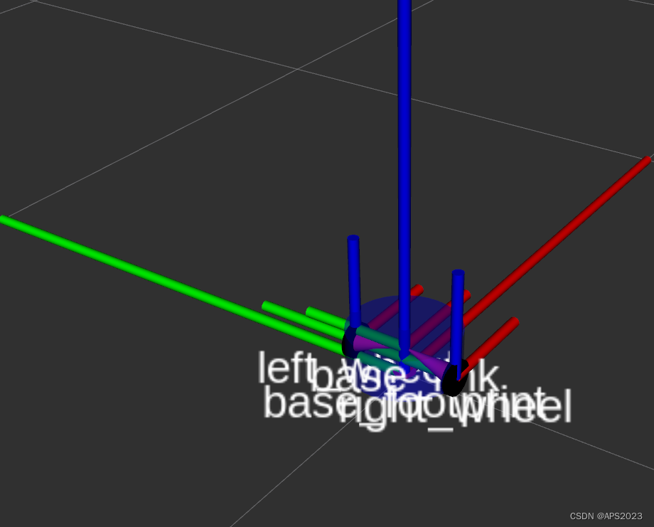
axis = 0 1 0我们需要设置欧拉角,让他是侧躺的。
需要沿着x(红色轴)翻转90度。
因此base_link到left_wheel的偏移是-0.0225米。
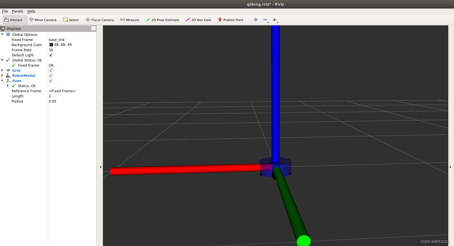
我们看看TF:
<robot name="mycar">
    <link name="base_footprint">
        <visual>
            <geometry>
                <sphere radius="0.001" />
            </geometry>
        </visual>
    </link>

    <link name="base_link">
        <visual>
            <geometry>
                <cylinder radius="0.1" length="0.08" />
            </geometry>
            <origin xyz="0 0 0" rpy="0 0 0" />
            <material name="blue">
                <color rgba="0 0 1.0 0.5" />
            </material>
        </visual>
    </link>

    <joint name="base_link2base_footprint" type="fixed">
        <parent link="base_footprint" />
        <child link="base_link"/>
        <origin xyz="0 0 0.055" />
    </joint>


    <link name="left_wheel">
        <visual>
            <geometry>
                <cylinder radius="0.0325" length="0.015" />
            </geometry>
            <origin xyz="0 0 0" rpy="1.5708 0 0" />
            <material name="wheel_color">
                <color rgba="0 0 1.0 0.5 0.3" />
            </material>
        </visual>
    </link>


    <link name="right_wheel">
        <visual>
            <geometry>
                <cylinder radius="0.0325" length="0.015" />
            </geometry>
            <origin xyz="0 0 0" rpy="1.5708 0 0" />
            <material name="wheel_color">
                <color rgba="0 0 1.0 0.5 0.3" />
            </material>
        </visual>
    </link>


    <joint name="base_link2left_wheel" type="continuous">
        <parent link="base_link" />
        <child link="left_wheel"/>
        <origin xyz="0 0.1 -0.0225" />
        <axis xyz="0 1 0" />
    </joint>


    <joint name="base_link2right_wheel" type="continuous">
        <parent link="base_link" />
        <child link="right_wheel"/>
        <origin xyz="0 -0.1 -0.0225" />
        <axis xyz="0 1 0" />
    </joint>

</robot>
2.2.5 万向轮添加
形状: 球体
半径: 0.75 cm
颜色: 黑色
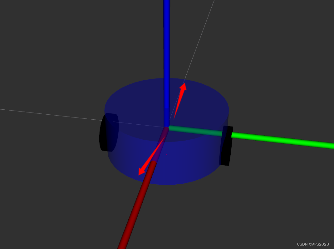
x有偏移,万向轮一般都小于车体的半径。车体的半径是10cm(0.10m),我们设置为0.08m,y上面没有偏移。
对于Z。关节在万象轮的中点。我们需要计算万向轮相对于车体中间节点的距离。车体距离地面是0.055米。万向轮中点距离地面是万向轮的半径0.0075。那么这个落差就是0.055-0.0075=0.0475。.
完整代码如下:
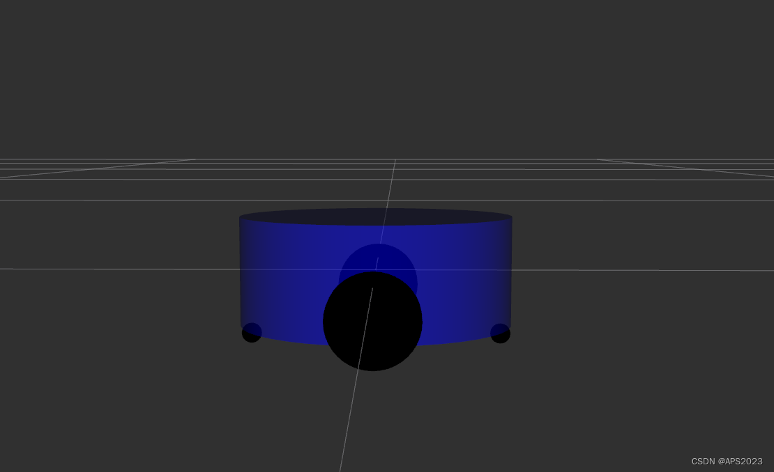
<robot name="mycar">
    <link name="base_footprint">
        <visual>
            <geometry>
                <sphere radius="0.001" />
            </geometry>
        </visual>
    </link>

    <link name="base_link">
        <visual>
            <geometry>
                <cylinder radius="0.1" length="0.08" />
            </geometry>
            <origin xyz="0 0 0" rpy="0 0 0" />
            <material name="blue">
                <color rgba="0 0 1.0 0.5" />
            </material>
        </visual>
    </link>

    <joint name="base_link2base_footprint" type="fixed">
        <parent link="base_footprint" />
        <child link="base_link"/>
        <origin xyz="0 0 0.055" />
    </joint>


    <link name="left_wheel">
        <visual>
            <geometry>
                <cylinder radius="0.0325" length="0.015" />
            </geometry>
            <origin xyz="0 0 0" rpy="1.5708 0 0" />
            <material name="wheel_color">
                <color rgba="0 0 1.0 0.5 0.3" />
            </material>
        </visual>
    </link>


    <link name="right_wheel">
        <visual>
            <geometry>
                <cylinder radius="0.0325" length="0.015" />
            </geometry>
            <origin xyz="0 0 0" rpy="1.5708 0 0" />
            <material name="wheel_color">
                <color rgba="0 0 1.0 0.5 0.3" />
            </material>
        </visual>
    </link>


    <joint name="base_link2left_wheel" type="continuous">
        <parent link="base_link" />
        <child link="left_wheel"/>
        <origin xyz="0 0.1 -0.0225" />
        <axis xyz="0 1 0" />
    </joint>


    <joint name="base_link2right_wheel" type="continuous">
        <parent link="base_link" />
        <child link="right_wheel"/>
        <origin xyz="0 -0.1 -0.0225" />
        <axis xyz="0 1 0" />
    </joint>


    <link name="front_wheel">
        <visual>
            <geometry>
                <sphere radius="0.0075" />
            </geometry>
            <origin xyz="0 0 0" rpy="0 0 0" />
            <material name="black">
                <color rgba="0.0 0.0 0.0 1.0" />
            </material>
        </visual>
    </link>

    <joint name="front_wheel2base_link" type="continuous">
        <parent link="base_link" />
        <child link="front_wheel" />
        <origin xyz="0.0925 0 -0.0475" />
        <axis xyz="1 1 1" />
    </joint>

    <link name="back_wheel">
        <visual>
            <geometry>
                <sphere radius="0.0075" />
            </geometry>
            <origin xyz="0 0 0" rpy="0 0 0" />
            <material name="black">
                <color rgba="0.0 0.0 0.0 1.0" />
            </material>
        </visual>
    </link>

    <joint name="back_wheel2base_link" type="continuous">
        <parent link="base_link" />
        <child link="back_wheel" />
        <origin xyz="-0.0925 0 -0.0475" />
        <axis xyz="1 1 1" />
    </joint>

</robot>
我们运行一下:
demo结束啦!
2.2.6 urdf工具
在 ROS 中,提供了一些工具来方便 URDF 文件的编写,比如:
check_urdf命令可以检查复杂的 urdf 文件是否存在语法问题
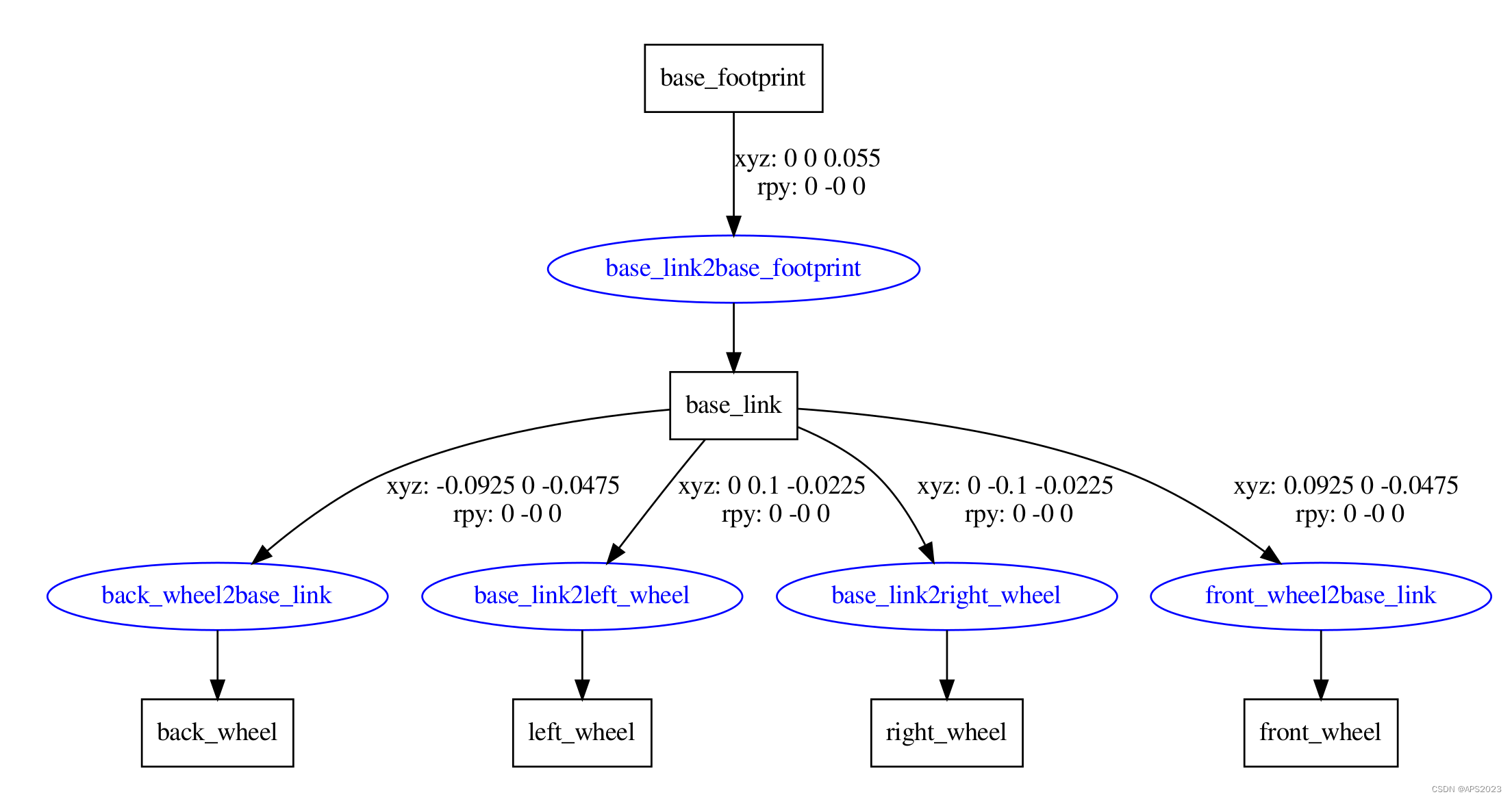
urdf_to_graphiz命令可以查看 urdf 模型结构,显示不同 link 的层级关系当然,要使用工具之前,首先需要安装,安装命令:
sudo apt install liburdfdom-toolscheck_urdf 语法检查:
liuhongwei@liuhongwei-Legion-Y9000P-IRX8H:~/Desktop/final/catkin_studyrobot/src/urdf/urdf$ check_urdf demo05.urdf
robot name is: mycar
---------- Successfully Parsed XML ---------------
root Link: base_footprint has 1 child(ren)
    child(1):  base_link
        child(1):  back_wheel
        child(2):  left_wheel
        child(3):  right_wheel
        child(4):  front_wheel
没问题会显示如下内容。
错误的话给给出报错信息的。
会显示机器人的。

3 Urdf优化--Xacro
3.1 应用场景
前面 URDF 文件构建机器人模型的过程中,存在若干问题。
问题1:在设计关节的位置时,需要按照一定的公式计算,公式是固定的,但是在 URDF 中依赖于人工计算,存在不便,容易计算失误,且当某些参数发生改变时,还需要重新计算。
问题2:URDF 中的部分内容是高度重复的,驱动轮与支撑轮的设计实现,不同轮子只是部分参数不同,形状、颜色、翻转量都是一致的,在实际应用中,构建复杂的机器人模型时,更是易于出现高度重复的设计,按照一般的编程涉及到重复代码应该考虑封装。......
如果在编程语言中,可以通过变量结合函数直接解决上述问题,在 ROS 中,已经给出了类似编程的优化方案,称之为:Xacro
Xacro 是 XML Macros 的缩写,Xacro 是一种 XML 宏语言,是可编程的 XML。
Xacro 可以声明变量,可以通过数学运算求解,使用流程控制控制执行顺序,还可以通过类似函数的实现,封装固定的逻辑,将逻辑中需要的可变的数据以参数的方式暴露出去,从而提高代码复用率以及程序的安全性。
较之于纯粹的 URDF 实现,可以编写更安全、精简、易读性更强的机器人模型文件,且可以提高编写效率。
3.2 利用xacro实现2.2案例实现(快速通关)
我们先来看一个写好的:
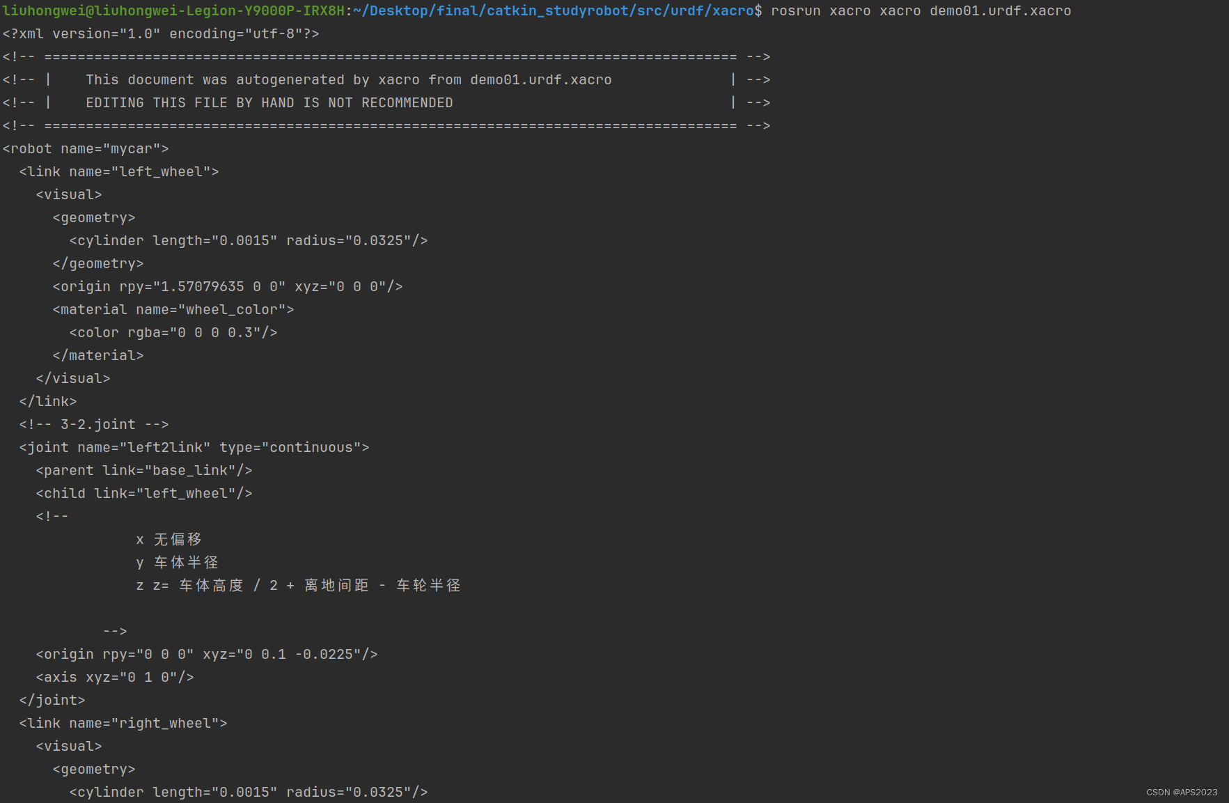
<robot name="mycar" xmlns:xacro="http://wiki.ros.org/xacro">
    <!-- 属性封装 -->
    <xacro:property name="wheel_radius" value="0.0325" />
    <xacro:property name="wheel_length" value="0.0015" />
    <xacro:property name="PI" value="3.1415927" />
    <xacro:property name="base_link_length" value="0.08" />
    <xacro:property name="lidi_space" value="0.015" />

    <!-- 宏 -->
    <xacro:macro name="wheel_func" params="wheel_name flag" >
        <link name="${wheel_name}_wheel">
            <visual>
                <geometry>
                    <cylinder radius="${wheel_radius}" length="${wheel_length}" />
                </geometry>

                <origin xyz="0 0 0" rpy="${PI / 2} 0 0" />

                <material name="wheel_color">
                    <color rgba="0 0 0 0.3" />
                </material>
            </visual>
        </link>

        <!-- 3-2.joint -->
        <joint name="${wheel_name}2link" type="continuous">
            <parent link="base_link"  />
            <child link="${wheel_name}_wheel" />
            <!--
                x 无偏移
                y 车体半径
                z z= 车体高度 / 2 + 离地间距 - 车轮半径

            -->
            <origin xyz="0 ${0.1 * flag} ${(base_link_length / 2 + lidi_space - wheel_radius) * -1}" rpy="0 0 0" />
            <axis xyz="0 1 0" />
        </joint>

    </xacro:macro>
    <xacro:wheel_func wheel_name="left" flag="1" />
    <xacro:wheel_func wheel_name="right" flag="-1" />
</robot>
很像函数哈哈。
如何将xacro转换成urdf呢?
rosrun xacro xacro demo01.urdf.xacro
成功!
rosrun xacro xacro demo01.urdf.xacro > 文件名称可以将urdf写入一个文件中。
3.3 XACRO语法详解
xacro 提供了可编程接口,类似于计算机语言,包括变量声明调用、函数声明与调用等语法实现。在使用 xacro 生成 urdf 时,根标签
robot中必须包含命名空间声明:xmlns:xacro="http://wiki.ros.org/xacro"
3.3.1 xmlns
<robot name="mycar" xmlns:xacro="http://wiki.ros.org/xacro">
</robot>
必须要这样的,robot name是机器人的名称。
3.3.2 属性与算数运算
用于封装 URDF 中的一些字段,比如: PAI 值,小车的尺寸,轮子半径 ....
<xacro:property name="xxxx" value="yyyy" />
<robot name="mycar" xmlns:xacro="http://wiki.ros.org/xacro">
    <xacro:property name="PI" value="3.1415927" />
    <xacro:property name="radius" value="0.03" />

</robot>
定义两个变量。
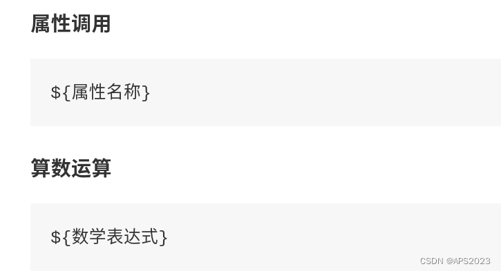
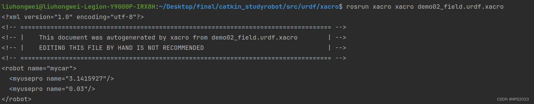
属性调用:我们来看看这个结果,证明xacro是可以编程的。
<robot name="mycar" xmlns:xacro="http://wiki.ros.org/xacro">
    <xacro:property name="PI" value="3.1415927" />
    <xacro:property name="radius" value="0.03" />

    <myusepro name="${PI}" />
    <myusepro name="${radius}" />
</robot>
算术运算呢?
<robot name="mycar" xmlns:xacro="http://wiki.ros.org/xacro">
    <xacro:property name="PI" value="3.1415927" />
    <xacro:property name="radius" value="0.03" />

    <myusepro name="${PI}" />
    <myusepro name="${radius}" />

    <myusecal result="${PI/2}" />
</robot>
OK!

3.3.3 宏
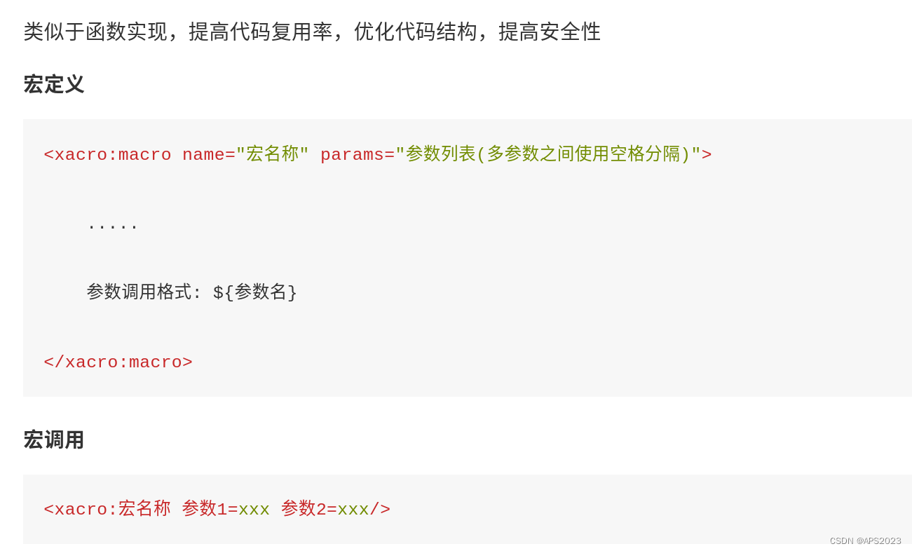
类似于函数实现,提高代码复用率,优化代码结构,提高安全性。
定义如下:
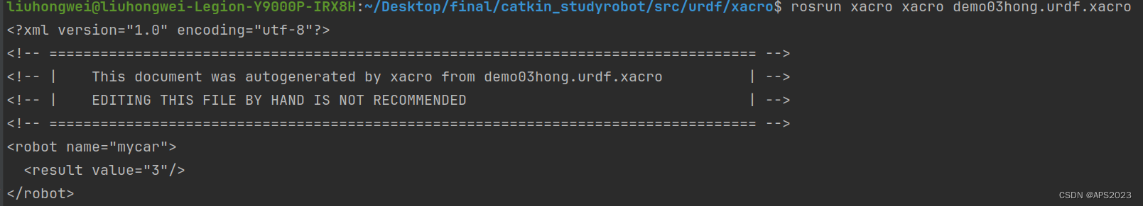
<robot name="mycar" xmlns:xacro="http://wiki.ros.org/xacro">

    <xacro:macro name="getSum" params="num1 num2">
        <result value="${num1 num2}" />
    </xacro:macro>

</robot>
调用如下:
<robot name="mycar" xmlns:xacro="http://wiki.ros.org/xacro">

    <xacro:macro name="getSum" params="num1 num2">
        <result value="${num1 + num2}" />
    </xacro:macro>

    <xacro:getSum num1="1" num2="2" />
</robot>
3.3.4 文件包含
机器人由多部件组成,不同部件可能封装为单独的 xacro 文件,最后再将不同的文件集成,组合为完整机器人,可以使用文件包含实现。
<robot name="xxx" xmlns:xacro="http://wiki.ros.org/xacro">
      <xacro:include filename="my_base.xacro" />
      <xacro:include filename="my_camera.xacro" />
      <xacro:include filename="my_laser.xacro" />
      ....
</robot>
3.4 用xacro完成2.2节的机器人的设计
3.4.1 添加xacro的链接
<robot name="mycar" xmlns:xacro="http://wiki.ros.org/xacro">


</robot>
3.4.2 base_footprint的实现
<robot name="mycar" xmlns:xacro="http://wiki.ros.org/xacro">
    <link name="base_footprint">
        <visual>
            <geometry>
                <sphere radius="0.001" />
            </geometry>
        </visual>
    </link>


</robot>
半径可以封装为xacro属性。
<robot name="mycar" xmlns:xacro="http://wiki.ros.org/xacro">
    <xacro:property name="footprint_radius" value="0.001"/>

    <link name="base_footprint">
        <visual>
            <geometry>
                <sphere radius="${footprint_radius}" />
            </geometry>
        </visual>
    </link>


</robot>
我们执行这个文件看看对不对。
没毛病。

3.4.3 底盘的实现
    <link name="base_link">
        <visual>
            <geometry>
                <cylinder radius="0.1" length="0.08" />
            </geometry>
            <origin xyz="0 0 0" rpy="0 0 0" />
            <material name="blue">
                <color rgba="0 0 1.0 0.5" />
            </material>
        </visual>
    </link>

    <joint name="base_link2base_footprint" type="fixed">
        <parent link="base_footprint" />
        <child link="base_link"/>
        <origin xyz="0 0 0.055" />
    </joint>
观察urdf文件,需要封装车体高度、离地偏移量、小车的半径高度。
<robot name="mycar" xmlns:xacro="http://wiki.ros.org/xacro">
    <xacro:property name="footprint_radius" value="0.001"/>
    <xacro:property name="base_radius" value="0.1"/>
    <xacro:property name="base_length" value="0.08"/>
    <xacro:property name="lidi" value="0.015"/>
    <xacro:property name="base_joint_z" value="${base_length/2 + lidi}"/>


    <link name="base_footprint">
        <visual>
            <geometry>
                <sphere radius="${footprint_radius}" />
            </geometry>
        </visual>
    </link>


    <link name="base_link">
        <visual>
            <geometry>
                <cylinder radius="${base_radius}" length="${base_length}" />
            </geometry>
            <origin xyz="0 0 0" rpy="0 0 0" />
            <material name="blue">
                <color rgba="0 0 1.0 0.5" />
            </material>
        </visual>
    </link>

    <joint name="base_link2base_footprint" type="fixed">
        <parent link="base_footprint" />
        <child link="base_link"/>
        <origin xyz="0 0 ${base_joint_z}" />
    </joint>

</robot>
执行!
没毛病!
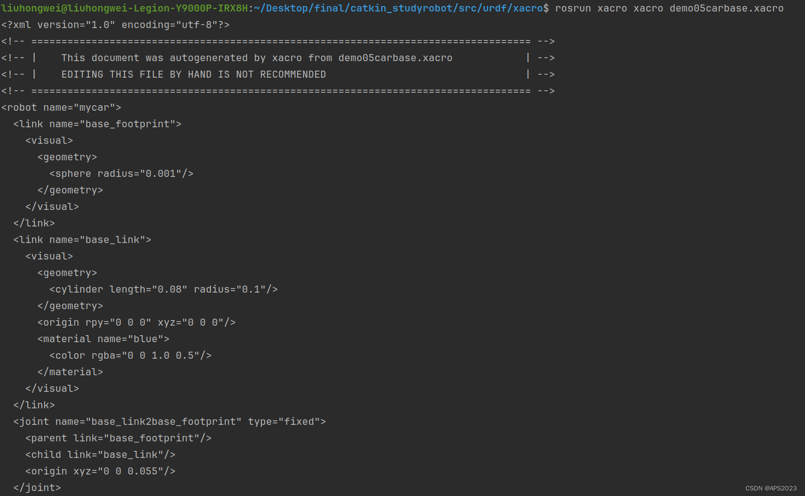
我们查看一下这个模型呢?在launch文件中集成xacro。
<launch>

    <param name="robot_description" command="$(find xacro)/xacro /home/liuhongwei/Desktop/final/catkin_studyrobot/src/urdf/xacro/demo05carbase.xacro" />

    <node pkg="rviz" type="rviz" name="rviz" args="-d /home/liuhongwei/Desktop/final/catkin_studyrobot/src/config/qidong.rviz " />
    <node pkg="joint_state_publisher" type="joint_state_publisher" name="joint_state_publisher" />
    <node pkg="robot_state_publisher" type="robot_state_publisher" name="robot_state_publisher" />
    <node pkg="joint_state_publisher_gui" type="joint_state_publisher_gui" name="joint_state_publisher_gui" />
</launch>
执行launch文件。
没毛病。

3.4.4 驱动轮的实现
看一下差异:link name和偏移量不同
<robot name="mycar" xmlns:xacro="http://wiki.ros.org/xacro">
    <xacro:property name="footprint_radius" value="0.001"/>
    <xacro:property name="base_radius" value="0.1"/>
    <xacro:property name="base_length" value="0.08"/>
    <xacro:property name="lidi" value="0.015"/>
    <xacro:property name="base_joint_z" value="${base_length/2 + lidi}"/>


    <link name="base_footprint">
        <visual>
            <geometry>
                <sphere radius="${footprint_radius}" />
            </geometry>
        </visual>
    </link>


    <link name="base_link">
        <visual>
            <geometry>
                <cylinder radius="${base_radius}" length="${base_length}" />
            </geometry>
            <origin xyz="0 0 0" rpy="0 0 0" />
            <material name="blue">
                <color rgba="0 0 1.0 0.5" />
            </material>
        </visual>
    </link>

    <joint name="base_link2base_footprint" type="fixed">
        <parent link="base_footprint" />
        <child link="base_link"/>
        <origin xyz="0 0 ${base_joint_z}" />
    </joint>


    <xacro:property name="wheel_radius" value="0.0325"/>
    <xacro:property name="wheel_length" value="0.015"/>
    <xacro:property name="PI" value="3.1415927"/>
    <xacro:property name="wheel_joint_Z" value="${-base_length/2-lidi+wheel_radius}"/>


    <xacro:macro name="wheel_func" params="wheel_name flag">
        <link name="${wheel_name}_wheel">
            <visual>
                <geometry>
                    <cylinder radius="${wheel_radius}" length="${wheel_length}" />
                </geometry>
                <origin xyz="0 0 0" rpy="${PI/2} 0 0" />
                <material name="wheel_color">
                    <color rgba="0 0 1.0 0.5 0.3" />
                </material>
            </visual>
        </link>


        <joint name="base_link2_${wheel_name}" type="continuous">
            <parent link="base_link" />
            <child link="${wheel_name}_wheel"/>
            <origin xyz="0 ${0.1 * flag} ${wheel_joint_Z}" />
            <axis xyz="0 1 0" />
        </joint>
    </xacro:macro>

    <xacro:wheel_func wheel_name="left" flag="1" />
    <xacro:wheel_func wheel_name="right" flag="-1" />


</robot>
Successfully!
3.4.5 万向轮的实现
<robot name="mycar" xmlns:xacro="http://wiki.ros.org/xacro">
    <xacro:property name="footprint_radius" value="0.001"/>
    <xacro:property name="base_radius" value="0.1"/>
    <xacro:property name="base_length" value="0.08"/>
    <xacro:property name="lidi" value="0.015"/>
    <xacro:property name="base_joint_z" value="${base_length/2 + lidi}"/>


    <link name="base_footprint">
        <visual>
            <geometry>
                <sphere radius="${footprint_radius}" />
            </geometry>
        </visual>
    </link>


    <link name="base_link">
        <visual>
            <geometry>
                <cylinder radius="${base_radius}" length="${base_length}" />
            </geometry>
            <origin xyz="0 0 0" rpy="0 0 0" />
            <material name="blue">
                <color rgba="0 0 1.0 0.5" />
            </material>
        </visual>
    </link>

    <joint name="base_link2base_footprint" type="fixed">
        <parent link="base_footprint" />
        <child link="base_link"/>
        <origin xyz="0 0 ${base_joint_z}" />
    </joint>


    <xacro:property name="wheel_radius" value="0.0325"/>
    <xacro:property name="wheel_length" value="0.015"/>
    <xacro:property name="PI" value="3.1415927"/>
    <xacro:property name="wheel_joint_Z" value="${-base_length/2-lidi+wheel_radius}"/>


    <xacro:macro name="wheel_func" params="wheel_name flag">
        <link name="${wheel_name}_wheel">
            <visual>
                <geometry>
                    <cylinder radius="${wheel_radius}" length="${wheel_length}" />
                </geometry>
                <origin xyz="0 0 0" rpy="${PI/2} 0 0" />
                <material name="wheel_color">
                    <color rgba="0 0 1.0 0.5 0.3" />
                </material>
            </visual>
        </link>


        <joint name="base_link2_${wheel_name}" type="continuous">
            <parent link="base_link" />
            <child link="${wheel_name}_wheel"/>
            <origin xyz="0 ${0.1 * flag} ${wheel_joint_Z}" />
            <axis xyz="0 1 0" />
        </joint>
    </xacro:macro>

    <xacro:wheel_func wheel_name="left" flag="1" />
    <xacro:wheel_func wheel_name="right" flag="-1" />

    <xacro:property name="small_radius" value="0.0075"/>
    <xacro:property name="small_jointz" value="${-base_length/2-lidi+small_radius}"/>

    <xacro:macro name="small_wheel_func" params="small_wheel_name flag">
        <link name="${small_wheel_name}_wheel">
            <visual>
                <geometry>
                    <sphere radius="${small_radius}" />
                </geometry>
                <origin xyz="0 0 0" rpy="0 0 0" />
                <material name="black">
                    <color rgba="0.0 0.0 0.0 1.0" />
                </material>
            </visual>
        </link>

        <joint name="${small_wheel_name}2base_link" type="continuous">
            <parent link="base_link" />
            <child link="${small_wheel_name}_wheel" />
            <origin xyz="${0.0925 * flag} 0 ${small_jointz}" />
            <axis xyz="1 1 1" />
        </joint>
    </xacro:macro>

    <xacro:small_wheel_func small_wheel_name="front" flag="1" />
    <xacro:small_wheel_func small_wheel_name="back" flag="-1" />


</robot>
启动!
3.5 案例
在前面小车底盘基础之上,添加摄像头和雷达传感器。
3.5.1 总体的xacro文件
<robot name="mycarwithlidarandcamera" xmlns:xacro="http://wiki.ros.org/xacro">
    <xacro:include filename="cam.xacro" />
    <xacro:include filename="lidar.xacro" />
    <xacro:include filename="demo05carbase.xacro" />

</robot>
包含三个子文件
3.5.2 总体的launch文件
<launch>

    <param name="robot_description" command="$(find xacro)/xacro /home/liuhongwei/Desktop/final/catkin_studyrobot/src/urdf/xacro/car_with_lidar_cam.xacro" />

    <node pkg="rviz" type="rviz" name="rviz" args="-d /home/liuhongwei/Desktop/final/catkin_studyrobot/src/config/qidong.rviz " />
    <node pkg="joint_state_publisher" type="joint_state_publisher" name="joint_state_publisher" />
    <node pkg="robot_state_publisher" type="robot_state_publisher" name="robot_state_publisher" />
    <node pkg="joint_state_publisher_gui" type="joint_state_publisher_gui" name="joint_state_publisher_gui" />
</launch>
先启动一下:
没毛病。
3.5.3 相机实现
摄像头的长宽高、偏移量都需要设置:
开始编程。
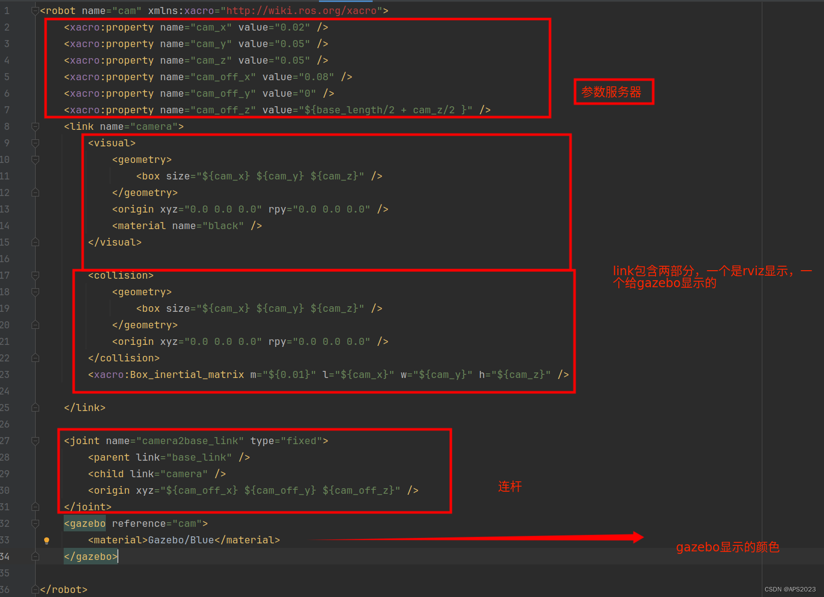
<robot name="cam" xmlns:xacro="http://wiki.ros.org/xacro">
    <xacro:property name="cam_x" value="0.02" />
    <xacro:property name="cam_y" value="0.05" />
    <xacro:property name="cam_z" value="0.05" />
    <xacro:property name="cam_off_x" value="0.08" />
    <xacro:property name="cam_off_y" value="0" />
    <xacro:property name="cam_off_z" value="${base_length/2 + cam_z/2 }" />

</robot>
设置连杆关节:
<robot name="cam" xmlns:xacro="http://wiki.ros.org/xacro">
    <xacro:property name="cam_x" value="0.02" />
    <xacro:property name="cam_y" value="0.05" />
    <xacro:property name="cam_z" value="0.05" />
    <xacro:property name="cam_off_x" value="0.08" />
    <xacro:property name="cam_off_y" value="0" />
    <xacro:property name="cam_off_z" value="${base_length/2 + cam_z/2 }" />
    <link name="camera">
        <visual>
            <geometry>
                <box size="${cam_x} ${cam_y} ${cam_z}" />
            </geometry>
            <origin xyz="0.0 0.0 0.0" rpy="0.0 0.0 0.0" />
            <material name="black" />
        </visual>
    </link>

    <joint name="camera2base_link" type="fixed">
        <parent link="base_link" />
        <child link="camera" />
        <origin xyz="${cam_off_x} ${cam_off_y} ${cam_off_z}" />
    </joint>
</robot>
再次运行launch文件。
成功!

3.5.4 雷达实现
雷达支架设计:支架圆柱的半径以及高度。
安装在车体中心,X、Y偏移量都是0。
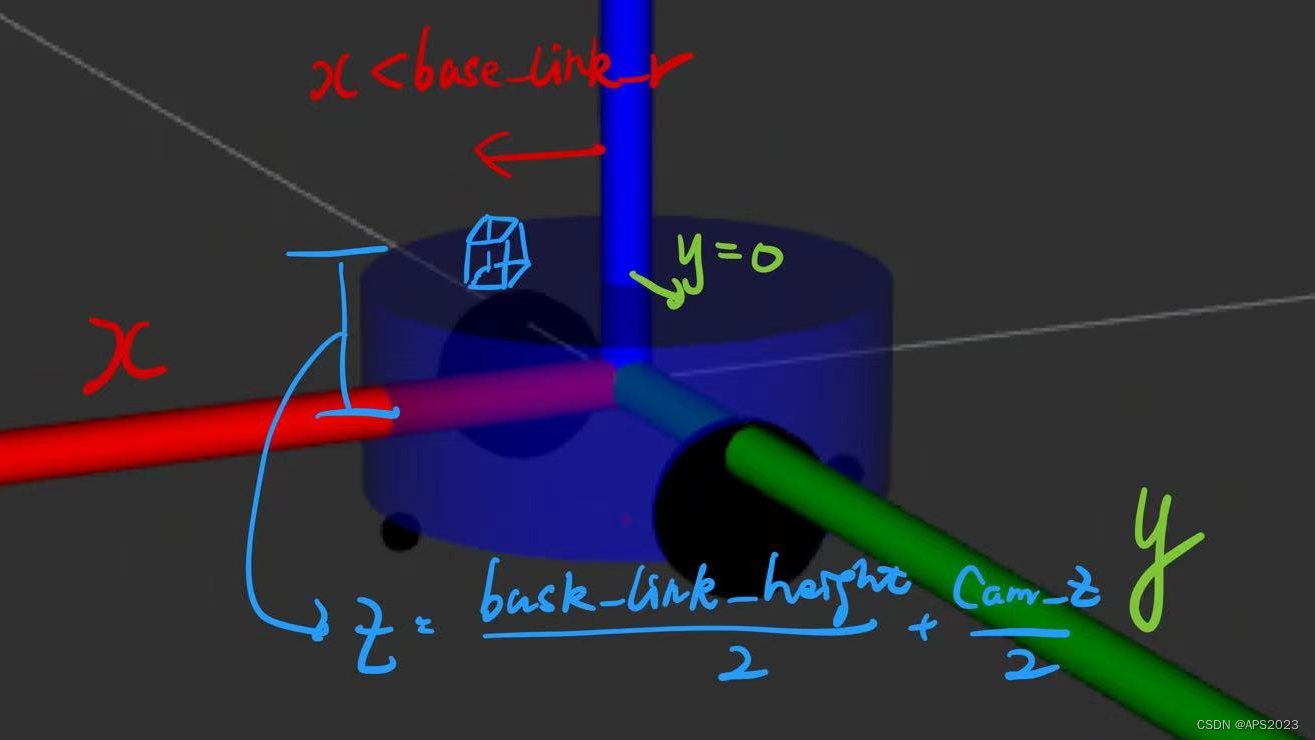
我们看Z的偏移量。很简单
<robot name="lidar" xmlns:xacro="http://wiki.ros.org/xacro">
    <xacro:property name="support_radius" value="0.01" />
    <xacro:property name="support_length" value="0.15" />
    <xacro:property name="laser_radius" value="0.03" />
    <xacro:property name="laser_length" value="0.05" />


    <xacro:property name="support_off_x" value="0" />
    <xacro:property name="support_off_y" value="0" />
    <xacro:property name="support_off_z" value="${ base_length/2 + laser_length/2 }" />
    <xacro:property name="lidar_off_x" value="0" />
    <xacro:property name="lidar_off_y" value="0" />
    <xacro:property name="lidar_off_z" value="${support_off_z/2 + laser_length/2}" />

</robot>
关节、link实现。
<robot name="lidar" xmlns:xacro="http://wiki.ros.org/xacro">
    <xacro:property name="support_radius" value="0.01" />
    <xacro:property name="support_length" value="0.15" />
    <xacro:property name="laser_radius" value="0.03" />
    <xacro:property name="laser_length" value="0.05" />


    <xacro:property name="support_off_x" value="0" />
    <xacro:property name="support_off_y" value="0" />
    <xacro:property name="support_off_z" value="${ base_length/2 + laser_length/2 }" />
    <xacro:property name="lidar_off_x" value="0" />
    <xacro:property name="lidar_off_y" value="0" />
    <xacro:property name="lidar_off_z" value="${support_off_z/2 + laser_length/2}" />


    <link name="support">
        <visual>
            <geometry>
                <cylinder radius="${support_radius}" length="${support_length}" />
            </geometry>
            <origin xyz="0.0 0.0 0.0" rpy="0.0 0.0 0.0" />
            <material name="red">
                <color rgba="0.8 0.2 0.0 0.8" />
            </material>
        </visual>
    </link>

    <joint name="support2base_link" type="fixed">
        <parent link="base_link" />
        <child link="support" />
        <origin xyz="${support_off_x} ${support_off_y} ${support_off_z}" />
    </joint>


    <link name="laser">
        <visual>
            <geometry>
                <cylinder radius="${laser_radius}" length="${laser_length}" />
            </geometry>
            <origin xyz="0.0 0.0 0.0" rpy="0.0 0.0 0.0" />
            <material name="black" />
        </visual>
    </link>

    <joint name="laser2support" type="fixed">
        <parent link="support" />
        <child link="laser" />
        <origin xyz="${lidar_off_x} ${lidar_off_y} ${lidar_off_z}" />
    </joint>

</robot>
最终效果:
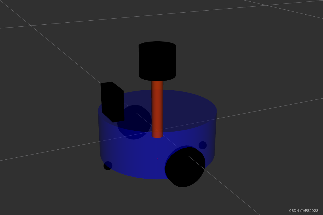
4 在RVIZ中控制机器人运动
通过 URDF 结合 rviz 可以创建并显示机器人模型,不过,当前实现的只是静态模型,如何控制模型的运动呢?在此,可以调用 Arbotix 实现此功能。
Arbotix:Arbotix 是一款控制电机、舵机的控制板,并提供相应的 ros 功能包,这个功能包的功能不仅可以驱动真实的 Arbotix 控制板,它还提供一个差速控制器,通过接受速度控制指令更新机器人的 joint 状态,从而帮助我们实现机器人在 rviz 中的运动。
这个差速控制器在 arbotix_python 程序包中,完整的 arbotix 程序包还包括多种控制器,分别对应 dynamixel 电机、多关节机械臂以及不同形状的夹持器。
实现流程:
安装 Arbotix
创建新功能包,准备机器人 urdf、xacro 文件
添加 Arbotix 配置文件
编写 launch 文件配置 Arbotix
启动 launch 文件并控制机器人模型运动
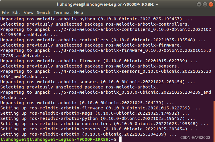
安装:
sudo apt-get install ros-melodic-arbotix
创建新功能包,准备机器人 urdf、xacro:urdf 和 xacro 调用上一讲实现即可
添加 arbotix 所需的配置文件:
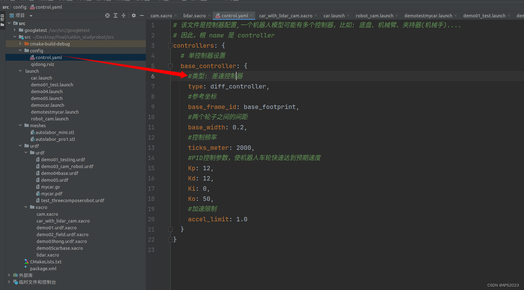
# 该文件是控制器配置,一个机器人模型可能有多个控制器,比如: 底盘、机械臂、夹持器(机械手)....
# 因此,根 name 是 controller
controllers: {
   # 单控制器设置
   base_controller: {
          #类型: 差速控制器
       type: diff_controller,
       #参考坐标
       base_frame_id: base_footprint,
       #两个轮子之间的间距
       base_width: 0.2,
       #控制频率
       ticks_meter: 2000,
       #PID控制参数,使机器人车轮快速达到预期速度
       Kp: 12,
       Kd: 12,
       Ki: 0,
       Ko: 50,
       #加速限制
       accel_limit: 1.0
    }
}
建立control.yaml
然后编写 launch 文件配置 Arbotix 节点:
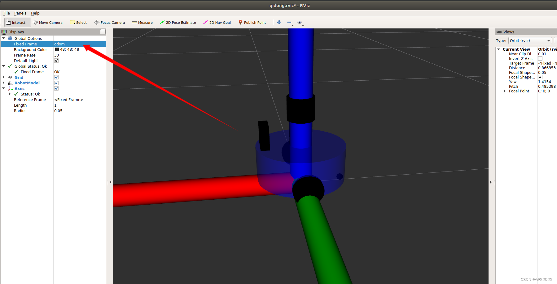
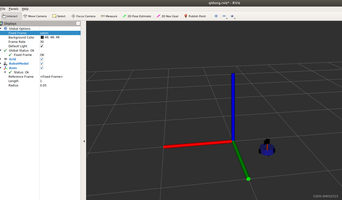
<launch>

    <param name="robot_description" command="$(find xacro)/xacro /home/liuhongwei/Desktop/final/catkin_studyrobot/src/urdf/xacro/car_with_lidar_cam.xacro" />

    <node pkg="rviz" type="rviz" name="rviz" args="-d /home/liuhongwei/Desktop/final/catkin_studyrobot/src/config/qidong.rviz " />
    <node pkg="joint_state_publisher" type="joint_state_publisher" name="joint_state_publisher" />
    <node pkg="robot_state_publisher" type="robot_state_publisher" name="robot_state_publisher" />


    <node pkg="arbotix_python" type="arbotix_driver" name="driver" output="screen">

        <rosparam command="load" file="/home/liuhongwei/Desktop/final/catkin_studyrobot/src/config/control.yaml" />
        <param name="sim" value="true" />
    </node>
</launch>
运行launch文件启动仿真环境。
选择odom坐标系。
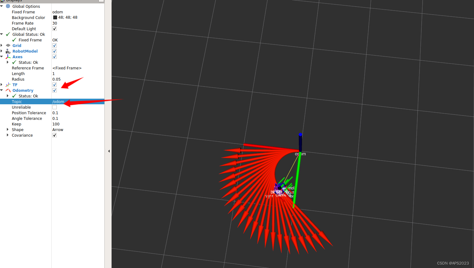
rostopic pub -r 10 /cmd_vel geometry_msgs/Twist '{linear: {x: 0.2, y: 0, z: 0}, angular: {x: 0, y: 0, z: 0.5}}'小车动起来了!
添加TF、ODOM。
5 Urdf集成gazebo
URDF 需要集成进 Rviz 或 Gazebo 才能显示可视化的机器人模型,前面已经介绍了URDF 与 Rviz 的集成,本节主要介绍:
- URDF 与 Gazebo 的基本集成流程;
- 如果要在 Gazebo 中显示机器人模型,URDF 需要做的一些额外配置;
- 关于Gazebo仿真环境的搭建。
5.1 URDF 与 Gazebo 集成流程
URDF 与 Gazebo 集成流程与 Rviz 实现类似,主要步骤如下:
创建功能包,导入依赖项
编写 URDF 或 Xacro 文件
启动 Gazebo 并显示机器人模型
在CMakeLists.txt中添加依赖:
find_package(catkin REQUIRED COMPONENTS
    roscpp
    rospy
    roslib
    # msg
    urdf
    xacro
        gazebo_ros
        gazebo_ros_control
        gazebo_plugins
)
在package.xml添加依赖:
  <build_depend>gazebo_ros</build_depend>
  <run_depend>gazebo_ros</run_depend>
  <build_depend>gazebo_ros_control</build_depend>
  <run_depend>gazebo_ros_control</run_depend>
  <build_depend>gazebo_plugins</build_depend>
  <run_depend>gazebo_plugins</run_depend>
注意, 当 URDF 需要与 Gazebo 集成时,和 Rviz 有明显区别: 1.必须使用 collision 标签,因为既然是仿真环境,那么必然涉及到碰撞检测,collision 提供碰撞检测的依据。2.必须使用 inertial 标签,此标签标注了当前机器人某个刚体部分的惯性矩阵,用于一些力学相关的仿真计算。
3.颜色设置,也需要重新使用 gazebo 标签标注,因为之前的颜色设置为了方便调试包含透明度,仿真环境下没有此选项。
collision如果是标准几何体,把geometry复制一下就好了:
        <collision>
            <geometry>
                <box size="0.5 0.2 0.1" />
            </geometry>
            <origin xyz="0.0 0.0 0.0" rpy="0.0 0.0 0.0" />
        </collision>
设置惯性矩阵(先忽略)、设置颜色:
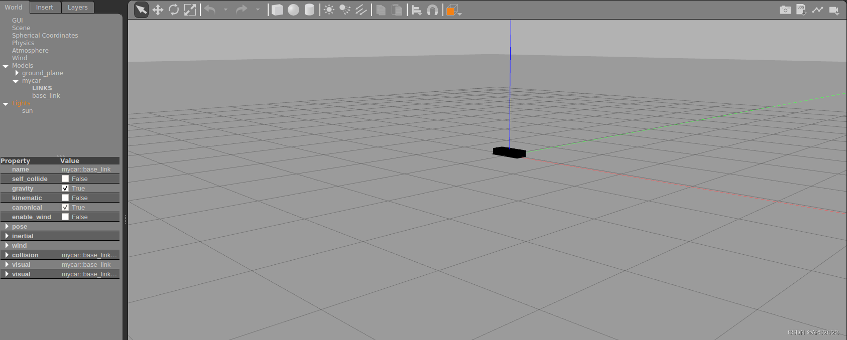
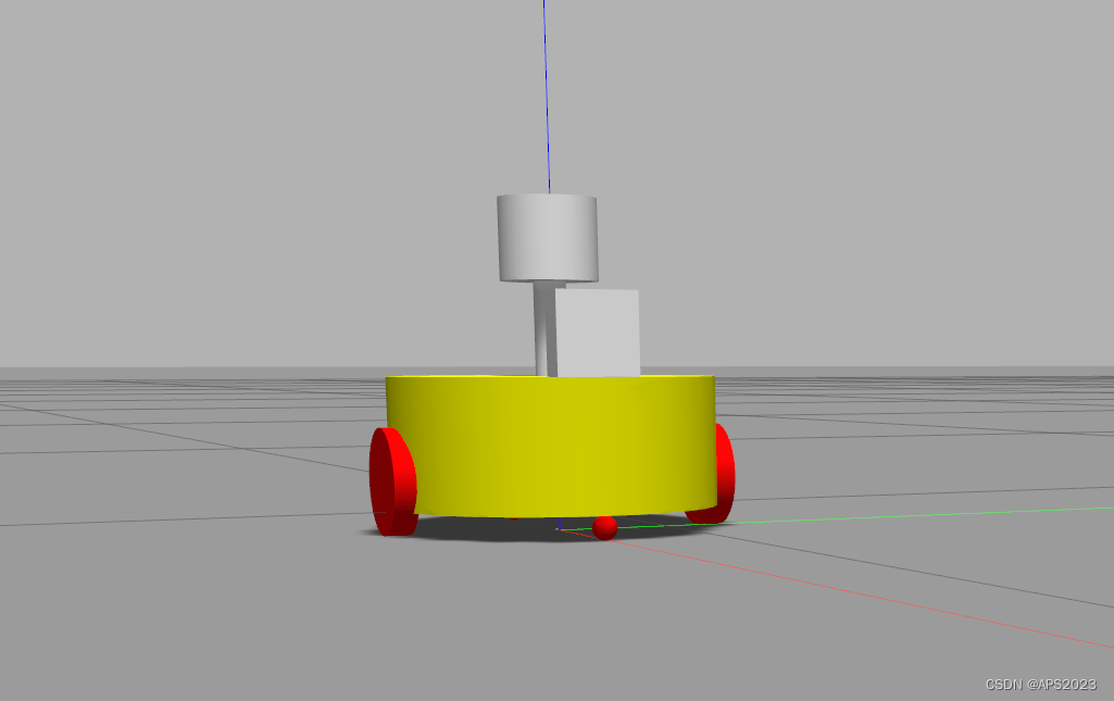
<!--
    创建一个机器人模型(盒状即可),显示在 Gazebo 中
-->

<robot name="mycar">
    <link name="base_link">
        <visual>
            <geometry>
                <box size="0.5 0.2 0.1" />
            </geometry>
            <origin xyz="0.0 0.0 0.0" rpy="0.0 0.0 0.0" />
            <material name="yellow">
                <color rgba="0.5 0.3 0.0 1" />
            </material>
        </visual>
        <collision>
            <geometry>
                <box size="0.5 0.2 0.1" />
            </geometry>
            <origin xyz="0.0 0.0 0.0" rpy="0.0 0.0 0.0" />
        </collision>
        <inertial>
            <origin xyz="0 0 0" />
            <mass value="6" />
            <inertia ixx="1" ixy="0" ixz="0" iyy="1" iyz="0" izz="1" />
        </inertial>
    </link>
    <gazebo reference="base_link">
        <material>Gazebo/Black</material>
    </gazebo>

</robot>
集成进launch文件:
<launch>

    <param name="robot_description" textfile="/home/liuhongwei/Desktop/final/catkin_studyrobot/src/urdf/urdf/gazebo_1.urdf" />

    <include file="$(find gazebo_ros)/launch/empty_world.launch" />

    <node pkg="gazebo_ros" type="spawn_model" name="model" args="-urdf -model mycar -param robot_description"  />
</launch>
启动launch文件,发现已经集成了。
5.2 计算方法(惯性矩阵等)
1.collision
如果机器人link是标准的几何体形状,和link的 visual 属性设置一致即可。
2.inertial
惯性矩阵的设置需要结合link的质量与外形参数动态生成,标准的球体、圆柱与立方体的惯性矩阵公式如下(已经封装为 xacro 实现):
球体惯性矩阵
<!-- Macro for inertia matrix -->
    <xacro:macro name="sphere_inertial_matrix" params="m r">
        <inertial>
            <mass value="${m}" />
            <inertia ixx="${2*m*r*r/5}" ixy="0" ixz="0"
                iyy="${2*m*r*r/5}" iyz="0"
                izz="${2*m*r*r/5}" />
        </inertial>
    </xacro:macro>
圆柱惯性矩阵
<xacro:macro name="cylinder_inertial_matrix" params="m r h">
        <inertial>
            <mass value="${m}" />
            <inertia ixx="${m*(3*r*r+h*h)/12}" ixy = "0" ixz = "0"
                iyy="${m*(3*r*r+h*h)/12}" iyz = "0"
                izz="${m*r*r/2}" />
        </inertial>
    </xacro:macro>
立方体惯性矩阵
 <xacro:macro name="Box_inertial_matrix" params="m l w h">
       <inertial>
               <mass value="${m}" />
               <inertia ixx="${m*(h*h + l*l)/12}" ixy = "0" ixz = "0"
                   iyy="${m*(w*w + l*l)/12}" iyz= "0"
                   izz="${m*(w*w + h*h)/12}" />
       </inertial>
   </xacro:macro>
需要注意的是,原则上,除了 base_footprint 外,机器人的每个刚体部分都需要设置惯性矩阵,且惯性矩阵必须经计算得出,如果随意定义刚体部分的惯性矩阵,那么可能会导致机器人在 Gazebo 中出现抖动,移动等现象。
3.颜色设置
在 gazebo 中显示 link 的颜色,必须要使用指定的标签:
<gazebo reference="link节点名称">
     <material>Gazebo/Blue</material>
</gazebo>
material 标签中,设置的值区分大小写,颜色可以设置为 Red Blue Green Black .....
5.3 实际操作:将机器人模型显示在gazebo里面
5.3.1 实现流程
需要编写封装惯性矩阵算法的 xacro 文件
为机器人模型中的每一个 link 添加 collision 和 inertial 标签,并且重置颜色属性
在 launch 文件中启动 gazebo 并添加机器人模型
5.3.2 编写封装惯性矩阵算法的 xacro 文件
interial.xacro 这个专业性太强了。
<robot name="base" xmlns:xacro="http://wiki.ros.org/xacro">
    <!-- Macro for inertia matrix -->
    <xacro:macro name="sphere_inertial_matrix" params="m r">
        <inertial>
            <mass value="${m}" />
            <inertia ixx="${2*m*r*r/5}" ixy="0" ixz="0"
                     iyy="${2*m*r*r/5}" iyz="0"
                     izz="${2*m*r*r/5}" />
        </inertial>
    </xacro:macro>

    <xacro:macro name="cylinder_inertial_matrix" params="m r h">
        <inertial>
            <mass value="${m}" />
            <inertia ixx="${m*(3*r*r+h*h)/12}" ixy = "0" ixz = "0"
                     iyy="${m*(3*r*r+h*h)/12}" iyz = "0"
                     izz="${m*r*r/2}" />
        </inertial>
    </xacro:macro>

    <xacro:macro name="Box_inertial_matrix" params="m l w h">
        <inertial>
            <mass value="${m}" />
            <inertia ixx="${m*(h*h + l*l)/12}" ixy = "0" ixz = "0"
                     iyy="${m*(w*w + l*l)/12}" iyz= "0"
                     izz="${m*(w*w + h*h)/12}" />
        </inertial>
    </xacro:macro>
</robot>
5.3.3 封装总的xacro(小车+雷达+相机+惯性)
<robot name="mycarwithlidarandcamera" xmlns:xacro="http://wiki.ros.org/xacro">


    <xacro:include filename="interial.xacro" />

    <xacro:include filename="demo05carbase.xacro" />
    <xacro:include filename="cam.xacro" />
    <xacro:include filename="lidar.xacro" />

</robot>
5.3.4 launch文件
<launch>

    <param name="robot_description" command="$(find xacro)/xacro /home/liuhongwei/Desktop/final/catkin_studyrobot/src/urdf/xacro/car_gazebo.xacro" />

    <include file="$(find gazebo_ros)/launch/empty_world.launch" />

    <node pkg="gazebo_ros" type="spawn_model" name="model" args="-urdf -model mycar -param robot_description"  />
</launch>
目前我们框架搭建完毕。
5.3.5 底盘修改
小车主体部分加颜色 + 惯性矩阵信息
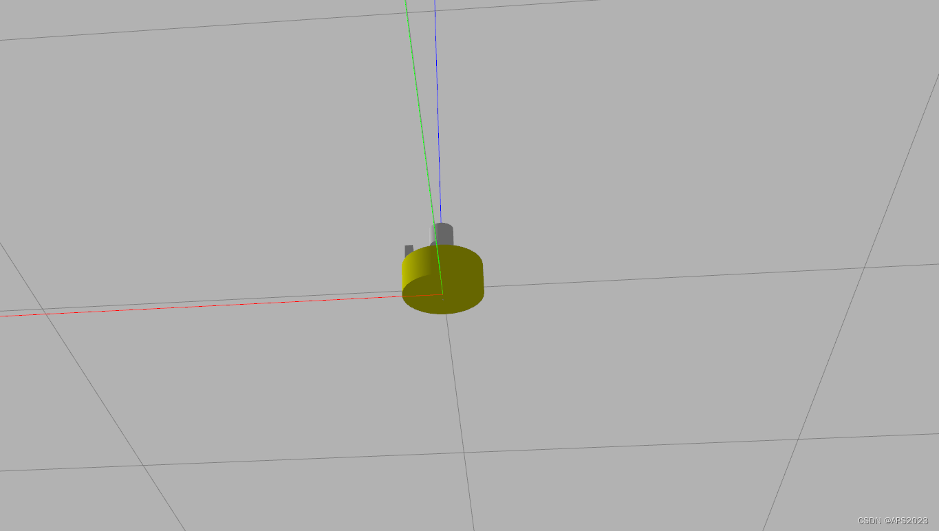
    <link name="base_link">
        <visual>
            <geometry>
                <cylinder radius="${base_radius}" length="${base_length}" />
            </geometry>
            <origin xyz="0 0 0" rpy="0 0 0" />
            <material name="blue">
                <color rgba="0 0 1.0 0.5" />
            </material>
        </visual>

        <collision>
            <geometry>
                <cylinder radius="${base_radius}" length="${base_length}" />
            </geometry>
            <origin xyz="0 0 0" rpy="0 0 0" />
        </collision>
        <xacro:cylinder_inertial_matrix m="${2}" r="${base_radius}" h="${base_length}" />
    </link>

    <gazebo reference="base_link">
        <material >
            Gazebo/Yellow
        </material>
    </gazebo>
执行launch文件:
小车主体部分已经有了~
驱动轮和支承轮也是同样道理,完整代码如下:
    <xacro:property name="wheel_radius" value="0.0325"/>
    <xacro:property name="wheel_length" value="0.015"/>
    <xacro:property name="PI" value="3.1415927"/>
    <xacro:property name="wheel_joint_Z" value="${-base_length/2-lidi+wheel_radius}"/>


    <xacro:macro name="wheel_func" params="wheel_name flag">
        <link name="${wheel_name}_wheel">
            <visual>
                <geometry>
                    <cylinder radius="${wheel_radius}" length="${wheel_length}" />
                </geometry>
                <origin xyz="0 0 0" rpy="${PI/2} 0 0" />
                <material name="wheel_color">
                    <color rgba="0 0 1.0 0.5 0.3" />
                </material>
            </visual>

            <collision>
                <geometry>
                    <cylinder radius="${wheel_radius}" length="${wheel_length}" />
                </geometry>
                <origin xyz="0.0 0.0 0.0" rpy="${PI / 2} 0.0 0.0" />
            </collision>
            <xacro:cylinder_inertial_matrix m="${1}" r="${wheel_radius}" h="${wheel_length}" />
        </link>

        <joint name="base_link2_${wheel_name}" type="continuous">
            <parent link="base_link" />
            <child link="${wheel_name}_wheel"/>
            <origin xyz="0 ${0.1 * flag} ${wheel_joint_Z}" />
            <axis xyz="0 1 0" />
        </joint>


        <gazebo reference="${wheel_name}_wheel">
            <material >
                Gazebo/Red
            </material>
        </gazebo>
    </xacro:macro>
最完整的代码如下:
<robot name="mycar" xmlns:xacro="http://wiki.ros.org/xacro">
    <xacro:property name="footprint_radius" value="0.001"/>
    <xacro:property name="base_radius" value="0.1"/>
    <xacro:property name="base_length" value="0.08"/>
    <xacro:property name="lidi" value="0.015"/>
    <xacro:property name="base_joint_z" value="${base_length/2 + lidi}"/>


    <link name="base_footprint">
        <visual>
            <geometry>
                <sphere radius="${footprint_radius}" />
            </geometry>
        </visual>
    </link>


    <link name="base_link">
        <visual>
            <geometry>
                <cylinder radius="${base_radius}" length="${base_length}" />
            </geometry>
            <origin xyz="0 0 0" rpy="0 0 0" />
            <material name="blue">
                <color rgba="0 0 1.0 0.5" />
            </material>
        </visual>

        <collision>
            <geometry>
                <cylinder radius="${base_radius}" length="${base_length}" />
            </geometry>
            <origin xyz="0 0 0" rpy="0 0 0" />
        </collision>
        <xacro:cylinder_inertial_matrix m="${2}" r="${base_radius}" h="${base_length}" />
    </link>

    <gazebo reference="base_link">
        <material >
            Gazebo/Yellow
        </material>
    </gazebo>

    <joint name="base_link2base_footprint" type="fixed">
        <parent link="base_footprint" />
        <child link="base_link"/>
        <origin xyz="0 0 ${base_joint_z}" />
    </joint>


    <xacro:property name="wheel_radius" value="0.0325"/>
    <xacro:property name="wheel_length" value="0.015"/>
    <xacro:property name="PI" value="3.1415927"/>
    <xacro:property name="wheel_joint_Z" value="${-base_length/2-lidi+wheel_radius}"/>


    <xacro:macro name="wheel_func" params="wheel_name flag">
        <link name="${wheel_name}_wheel">
            <visual>
                <geometry>
                    <cylinder radius="${wheel_radius}" length="${wheel_length}" />
                </geometry>
                <origin xyz="0 0 0" rpy="${PI/2} 0 0" />
                <material name="wheel_color">
                    <color rgba="0 0 1.0 0.5 0.3" />
                </material>
            </visual>

            <collision>
                <geometry>
                    <cylinder radius="${wheel_radius}" length="${wheel_length}" />
                </geometry>
                <origin xyz="0.0 0.0 0.0" rpy="${PI / 2} 0.0 0.0" />
            </collision>
            <xacro:cylinder_inertial_matrix m="${1}" r="${wheel_radius}" h="${wheel_length}" />
        </link>

        <joint name="base_link2_${wheel_name}" type="continuous">
            <parent link="base_link" />
            <child link="${wheel_name}_wheel"/>
            <origin xyz="0 ${0.1 * flag} ${wheel_joint_Z}" />
            <axis xyz="0 1 0" />
        </joint>


        <gazebo reference="${wheel_name}_wheel">
            <material >
                Gazebo/Red
            </material>
        </gazebo>
    </xacro:macro>


    <xacro:wheel_func wheel_name="left" flag="1" />
    <xacro:wheel_func wheel_name="right" flag="-1" />

    <xacro:property name="small_radius" value="0.0075"/>
    <xacro:property name="small_jointz" value="${-base_length/2-lidi+small_radius}"/>

    <xacro:macro name="small_wheel_func" params="small_wheel_name flag">
        <link name="${small_wheel_name}_wheel">
            <visual>
                <geometry>
                    <sphere radius="${small_radius}" />
                </geometry>
                <origin xyz="0 0 0" rpy="0 0 0" />
                <material name="black">
                    <color rgba="0.0 0.0 0.0 0.6" />
                </material>
            </visual>
            <collision>
                <geometry>
                    <sphere radius="${small_radius}" />
                </geometry>
                <origin xyz="0 0 0" rpy="0 0 0" />
            </collision>
            <xacro:sphere_inertial_matrix m="${0.08}" r="${small_radius}" />
        </link>


        <joint name="${small_wheel_name}2base_link" type="continuous">
            <parent link="base_link" />
            <child link="${small_wheel_name}_wheel" />
            <origin xyz="${0.0925 * flag} 0 ${small_jointz}" />
            <axis xyz="1 1 1" />
        </joint>

        <gazebo reference="${small_wheel_name}_wheel">
            <material >
                Gazebo/Red
            </material>
        </gazebo>
    </xacro:macro>

    <xacro:small_wheel_func small_wheel_name="front" flag="1" />
    <xacro:small_wheel_func small_wheel_name="back" flag="-1" />


</robot>
gazebo显示!
5.3.6 传感器修改
总结了一下。
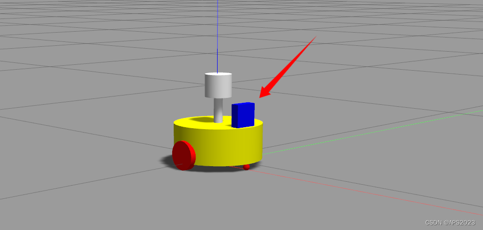
<robot name="cam" xmlns:xacro="http://wiki.ros.org/xacro">
    <xacro:property name="cam_x" value="0.02" />
    <xacro:property name="cam_y" value="0.05" />
    <xacro:property name="cam_z" value="0.05" />
    <xacro:property name="cam_off_x" value="0.08" />
    <xacro:property name="cam_off_y" value="0" />
    <xacro:property name="cam_off_z" value="${base_length/2 + cam_z/2 }" />
    <link name="camera">
        <visual>
            <geometry>
                <box size="${cam_x} ${cam_y} ${cam_z}" />
            </geometry>
            <origin xyz="0.0 0.0 0.0" rpy="0.0 0.0 0.0" />
            <material name="black" />
        </visual>

        <collision>
            <geometry>
                <box size="${cam_x} ${cam_y} ${cam_z}" />
            </geometry>
            <origin xyz="0.0 0.0 0.0" rpy="0.0 0.0 0.0" />
        </collision>
        <xacro:Box_inertial_matrix m="${0.01}" l="${cam_x}" w="${cam_y}" h="${cam_z}" />

    </link>

    <joint name="camera2base_link" type="fixed">
        <parent link="base_link" />
        <child link="camera" />
        <origin xyz="${cam_off_x} ${cam_off_y} ${cam_off_z}" />
    </joint>
    <gazebo reference="camera">
        <material>Gazebo/Blue</material>
    </gazebo>

</robot>
图片上有个错误,gazebo reference应该和link name一致的。
再设置下雷达:
雷达有两个连杆,因此要设置两次:
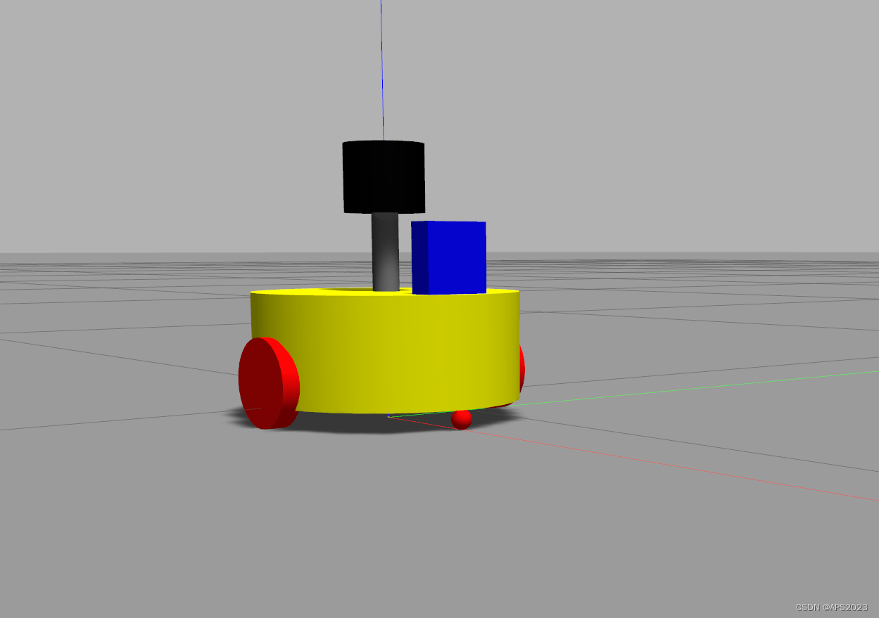
<robot name="lidar" xmlns:xacro="http://wiki.ros.org/xacro">
    <xacro:property name="support_radius" value="0.01" />
    <xacro:property name="support_length" value="0.15" />
    <xacro:property name="laser_radius" value="0.03" />
    <xacro:property name="laser_length" value="0.05" />


    <xacro:property name="support_off_x" value="0" />
    <xacro:property name="support_off_y" value="0" />
    <xacro:property name="support_off_z" value="${ base_length/2 + laser_length/2 }" />
    <xacro:property name="lidar_off_x" value="0" />
    <xacro:property name="lidar_off_y" value="0" />
    <xacro:property name="lidar_off_z" value="${support_off_z/2 + laser_length/2}" />


    <link name="support">
        <visual>
            <geometry>
                <cylinder radius="${support_radius}" length="${support_length}" />
            </geometry>
            <origin xyz="0.0 0.0 0.0" rpy="0.0 0.0 0.0" />
            <material name="red">
                <color rgba="0.8 0.2 0.0 0.8" />
            </material>
        </visual>
        <collision>
            <geometry>
                <cylinder radius="${support_radius}" length="${support_length}" />
            </geometry>
            <origin xyz="0.0 0.0 0.0" rpy="0.0 0.0 0.0" />
        </collision>
        <xacro:cylinder_inertial_matrix m="${0.1}" r="${support_radius}" h="${support_length}" />
    </link>

    <gazebo reference="support">
        <material>Gazebo/Grey</material>
    </gazebo>

    <joint name="support2base_link" type="fixed">
        <parent link="base_link" />
        <child link="support" />
        <origin xyz="${support_off_x} ${support_off_y} ${support_off_z}" />
    </joint>


    <link name="laser">
        <visual>
            <geometry>
                <cylinder radius="${laser_radius}" length="${laser_length}" />
            </geometry>
            <origin xyz="0.0 0.0 0.0" rpy="0.0 0.0 0.0" />
            <material name="black" />
        </visual>

        <collision>
            <geometry>
                <cylinder radius="${laser_radius}" length="${laser_length}" />
            </geometry>
            <origin xyz="0.0 0.0 0.0" rpy="0.0 0.0 0.0" />
        </collision>
        <xacro:cylinder_inertial_matrix m="${0.15}" r="${laser_radius}" h="${laser_length}" />

    </link>

    <joint name="laser2support" type="fixed">
        <parent link="support" />
        <child link="laser" />
        <origin xyz="${lidar_off_x} ${lidar_off_y} ${lidar_off_z}" />
    </joint>
    <gazebo reference="laser">
        <material>Gazebo/Black</material>
    </gazebo>

</robot>
运行launch文件:
OK啦!
6 Gazebo仿真环境搭建
在gazebo中显示别人搭建好的仿真环境。
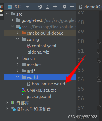
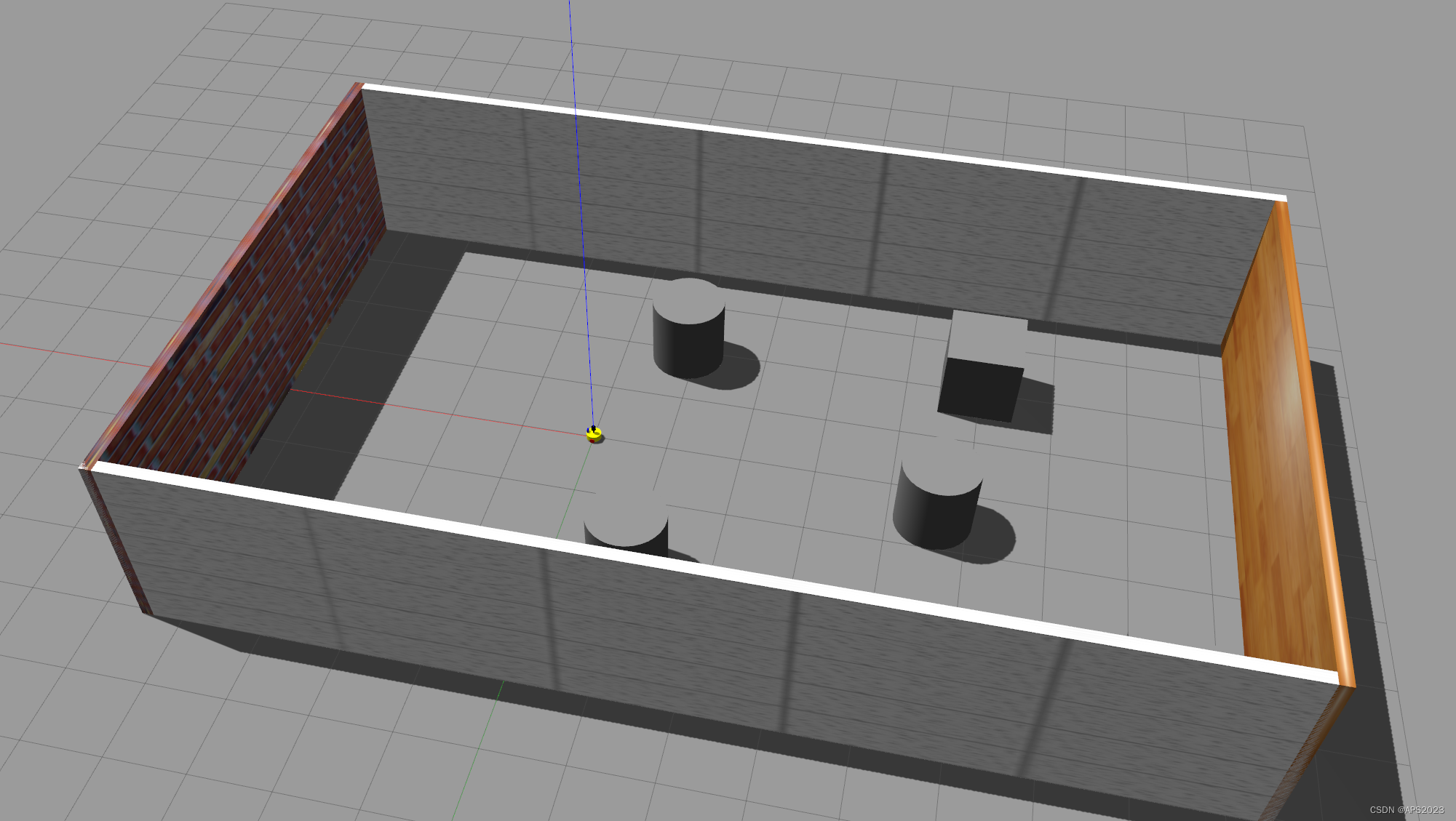
建立world文件夹,放入事先建立好的world文件。
<launch>

    <param name="robot_description" command="$(find xacro)/xacro /home/liuhongwei/Desktop/final/catkin_studyrobot/src/urdf/xacro/car_gazebo.xacro" />

    <include file="$(find gazebo_ros)/launch/empty_world.launch">
        <arg name="world_name" value="/home/liuhongwei/Desktop/final/catkin_studyrobot/src/world/box_house.world" />
    </include>

    <node pkg="gazebo_ros" type="spawn_model" name="model" args="-urdf -model mycar -param robot_description"  />
</launch>
执行!
成功!