1. 说明
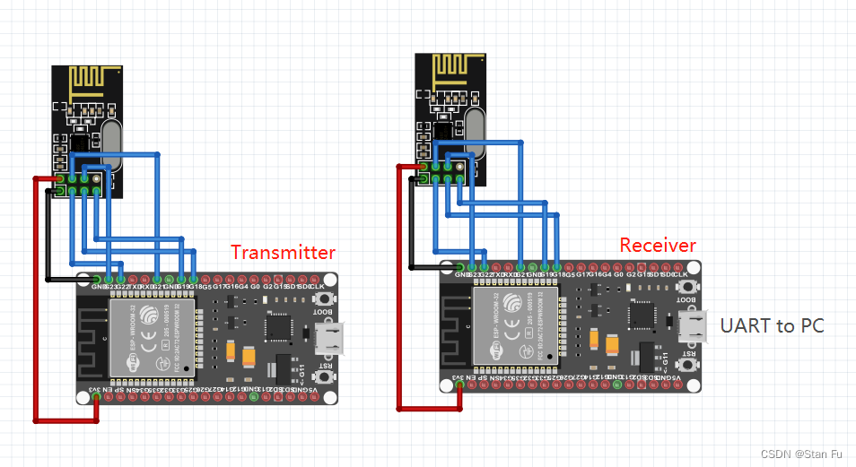
最近做四轴的时候使用到了NRF24L01,但是并没有合适的设备来进行测试。所以为了快速测试通信协议,这里使用了基于Arduino框架的ESP32来进行测试。测试的目标是实现两个ESP之间基于NRF24L01的通信,并使用UART输出接收到的信息。为了方便后期的开发,这里我使用了PlatformIO平台来进行环境的配置。 ESP32 使用了两块 ESP32-WROVER-kitc。
NRF24L01使用 2.4 GHz 频段,可以在 250 kbps 到 2 Mbps 的波特率下运行。如果在开放空间和较低波特率下使用,其范围可达 100 米。
2. 接线
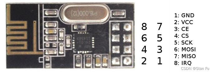
首先是NRF24L01的接线,其采用SPI作为通信方式。其中IRQ为可选线,可以不接。两个板子的接线完全相同。
| Nr | NRF24L01 | ESP32 |
|---|---|---|
| 1 | GND | GND |
| 2 | VCC | 3.3V |
| 3 | (CE) | 22 |
| 4 | (CSN) | 21 |
| 5 | (SCK) | 18 |
| 6 | (MOSI) | 23 |
| 7 | (MISO) | 19 |
| 8 | IRQ * | 4* |
∗ * ∗: 中断线是可选的
3. 环境
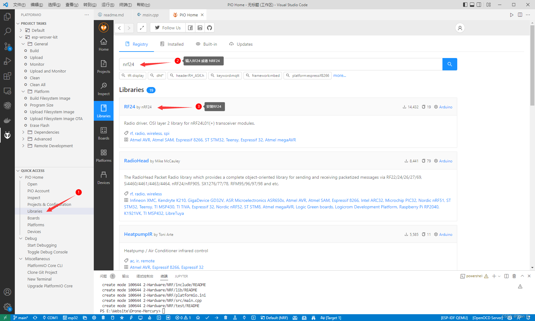
如上所述,采用PlatformIO作为开发环境,使用Arduino框架。为了能使用NRF24L01,需要添加RF24库。 配置方法如下。
4. 程序
环境配置好之后,就可以下载程序验证了。 程序参考此处, 不同的是更改了CE和CS脚的GPIO口。
4.1 发送者
这部分是发送者代码,主要任务是循环发送数据。我们将代码下载到一个ESP32之后直接将其连接电源就可以了,并不需要查看发送者的输出。
// SimpleTx - the master or the transmitter
#include <Arduino.h>
#include <SPI.h>
#include <nRF24L01.h>
#include <RF24.h>

#define CE_PIN  22
#define CSN_PIN 21

void updateMessage(void);
void send(void);

const byte slaveAddress[5] = {

    'R','x','A','A','A'};


RF24 radio(CE_PIN, CSN_PIN); // Create a Radio

char dataToSend[10] = "Message 0";
char txNum = '0';


unsigned long currentMillis;
unsigned long prevMillis;
unsigned long txIntervalMillis = 1000; // send once per second


void setup() {


    Serial.begin(9600);

    Serial.println("SimpleTx Starting");

    radio.begin();
    radio.setDataRate( RF24_250KBPS );
    radio.setRetries(3,5); // delay, count
    radio.openWritingPipe(slaveAddress);
}

//====================

void loop() {


    currentMillis = millis();
    if (currentMillis - prevMillis >= txIntervalMillis) {


        send();
        prevMillis = millis();
    }
}

//====================

void send() {


    bool rslt;
    rslt = radio.write( &dataToSend, sizeof(dataToSend) );
        // Always use sizeof() as it gives the size as the number of bytes.
        // For example if dataToSend was an int sizeof() would correctly return 2

    Serial.print("Data Sent ");
    Serial.print(dataToSend);
    if (rslt) {


        Serial.println("  Acknowledge received");
        updateMessage();
    }
    else {


        Serial.println("  Tx failed");
    }
}

//================

void updateMessage() {


        // so you can see that new data is being sent
    txNum += 1;
    if (txNum > '9') {


        txNum = '0';
    }
    dataToSend[8] = txNum;
}
4.2 接收者
这部分是接受者代码, 其任务是接收发送者的信息,并使用UART将得到的信息打印到终端。
// SimpleRx - the slave or the receiver
#include <Arduino.h>
#include <SPI.h>
#include <nRF24L01.h>
#include <RF24.h>

void getData(void);
void showData(void);

#define CE_PIN  22
#define CSN_PIN 21

const byte thisSlaveAddress[5] = {

    'R','x','A','A','A'};

RF24 radio(CE_PIN, CSN_PIN);

char dataReceived[10]; // this must match dataToSend in the TX
bool newData = false;

//===========

void setup() {


    Serial.begin(9600);

    Serial.println("SimpleRx Starting");
    radio.begin();
    radio.setDataRate( RF24_250KBPS );
    radio.openReadingPipe(1, thisSlaveAddress);
    radio.startListening();
}

//=============

void loop() {


    getData();
    showData();
}

//==============

void getData() {


    if ( radio.available() ) {


        radio.read( &dataReceived, sizeof(dataReceived) );
        newData = true;
    }
}

void showData() {


    if (newData == true) {


        Serial.print("Data received ");
        Serial.println(dataReceived);
        newData = false;
    }
}
5. 输出
在终端中得到的输出如下即为测试成功,
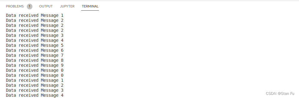
注意这里为接收者得到的输出,发送者的UART输出有所不同。