Robot Vacuum Driving Modes
Introduction
Background
As you’ve just learned, using hierarchy in your Stateflow models helps you group states with common functionality. In this project, you will use hierarchy to model something similar to the driving logic of the robotic vacuum that you previously modeled. In that project, the robot could drive in two modes: docking or vacuuming. The robot’s instructions for each of these modes were:
(正如您刚刚学到的,在Stateflow模型中使用层次结构可以帮助您使用通用功能对状态进行分组。在这个项目中,您将使用层次结构来建模类似于您之前建模的机器人真空的驱动逻辑的东西。在该项目中,机器人可以以两种模式驱动:对接或抽真空。机器人对每种模式的指示如下:)
SeekDock – drive to the dock and then stop.(SeekDock–行驶至码头,然后停车。)
Vacuum – drive to the corner of the room and then follow a zig-zag pattern.(吸尘器——开到房间的角落,然后按照Z字形行驶。)
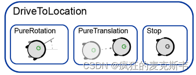
Thus, the robot required two driving behaviors: drive to a location and follow a zig-zag pattern. These can be implemented as the top-level states in a hierarchy. The substates for each are the particular states required to implement each behavior. For example, when driving to a location, the robot’s motion can be broken down into: orient using pure rotation, drive using pure translation, and stop.
(因此,机器人需要两种驾驶行为:驾驶到一个位置和遵循Z字形模式。这些可以实现为层次结构中的顶级状态。每个的子状态是实现每个行为所需的特定状态。例如,当行驶到一个位置时,机器人的运动可以分解为:使用纯旋转进行定向,使用纯平移进行驱动,以及停止。)
Project
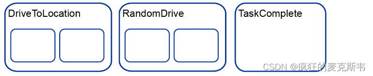
In this project, you will implement a driving pattern in which the robot can either dock or drive a random pattern around the room. (Many early or discount models of robotic vacuums follow a random pattern, which is simple to implement, although less efficient than using a map.) Thus, DriveToLocation and RandomDrive are two superstates. Your Stateflow chart will also have a TaskComplete state in which no further driving commands are sent.
(在这个项目中,你将实现一种驱动模式,在这种模式下,机器人可以停靠或驱动房间周围的随机模式。(许多早期或折扣型号的机器人真空吸尘器都遵循随机模式,这很容易实现,尽管效率不如使用地图。)因此,DriveToLocation和RandomDrive是两种超级状态。您的状态流程图也将处于TaskComplete状态,在该状态下不会发送进一步的驱动命令。)
As with the Robot Vacuum Supervisory Control project, the driving dynamics of the robotic vacuum have been built in Simulink. You will connect simulated sensor data and other information from this model to your Stateflow chart in order to set the desired velocity and angular velocity commands to be sent to the robot.
(与机器人真空监控项目一样,在Simulink中建立了机器人真空的驱动动力学。您将此模型中的模拟传感器数据和其他信息连接到状态流程图,以便设置要发送到机器人的所需速度和角速度命令。)
You will build this model in two parts. In Part 1, you will define the high-level structure of the driving mode logic. Then, in Part 2, you will fill in the implementation details and connect the Stateflow chart to Simulink.
(您将分两部分构建此模型。在第1部分中,您将定义驾驶模式逻辑的高级结构。然后,在第2部分中,您将填写实现细节,并将Stateflow图表连接到Simulink。)
Part1
Task1(任务1)
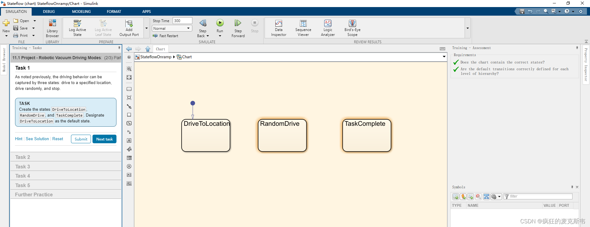
As noted previously, the driving behavior can be captured by three states: drive to a specified location, drive randomly, and stop.
(如前所述,驾驶行为可以通过三种状态来捕捉:驾驶到指定位置、随机驾驶和停车。)
Create the states DriveToLocation, RandomDrive, and TaskComplete. Designate DriveToLocation as the default state.
(创建状态DriveToLocation、RandomDrive和TaskComplete。将DriveToLocation指定为默认状态。)
Task2(任务2)
Although there are three internal states to this system, there are only two overall drive modes.
(尽管该系统有三种内部状态,但总体上只有两种驱动模式。)
1.Drive to the dock.(开车到码头。)
2.Drive to the center of the room, then begin the random pattern.(开车到房间中央,然后开始随机模式。)
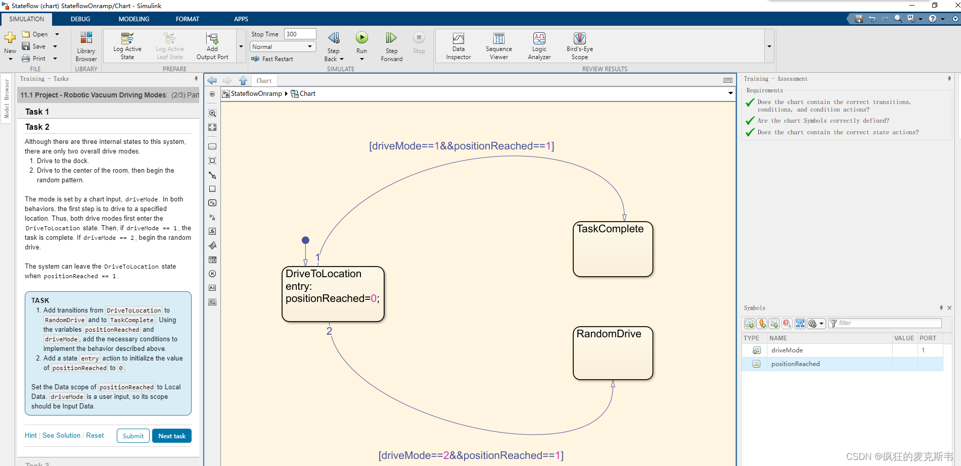
The mode is set by a chart input, driveMode. In both behaviors, the first step is to drive to a specified location. Thus, both drive modes first enter the DriveToLocation state. Then, if driveMode == 1, the task is complete. If driveMode2, begin the random drive.
(该模式由图表输入driveMode设置。在这两种行为中,第一步是将车开到指定的位置。因此,两种驾驶模式都首先进入DriveToLocation状态。然后,如果driveMode1,则任务完成。如果driveMode2,则开始随机驾驶。)
The system can leave the DriveToLocation state when positionReached == 1.
(positionReached ==1时,系统可以离开DriveToLocation State。)
-
Add transitions from DriveToLocation to RandomDrive and to TaskComplete. Using the variables positionReached and driveMode, add the necessary conditions to implement the behavior described above.
(1.添加从DriveToLocation到RandomDrive和askComplete的转换。使用变量positionReached和driveMode,添加必要的条件以实现上述行为。)扫描二维码关注公众号,回复: 16522706 查看本文章
-
Add a state entry action to initialize the value of positionReached to 0.
(2.添加一个状态entry操作,将positionReached的值初始化为0。)
Set the Data scope of positionReached to Local Data. driveMode is a user input, so its scope should be Input Data.
Task3(任务3)
The random vacuum task consists of driving until bumping into a wall, rotating a random amount, and repeating the bump/rotate sequence. The task is complete after the bump sensor registers more than 50 times.
(随机真空任务包括驾驶直到撞到墙上,旋转随机量,并重复碰撞/旋转序列。在通气传感器注册超过50次之后,该任务就完成了。)
Add the appropriate transition and condition based on a counter, bumpCount. Set bumpCount to 0 upon entering the RandomDrive state.
(根据计数器bumpCount添加适当的转换和条件。进入RandomDrive状态时,将bumpCount设置为0。)
Define the Symbol as Local Data.(将符号定义为本地数据。)

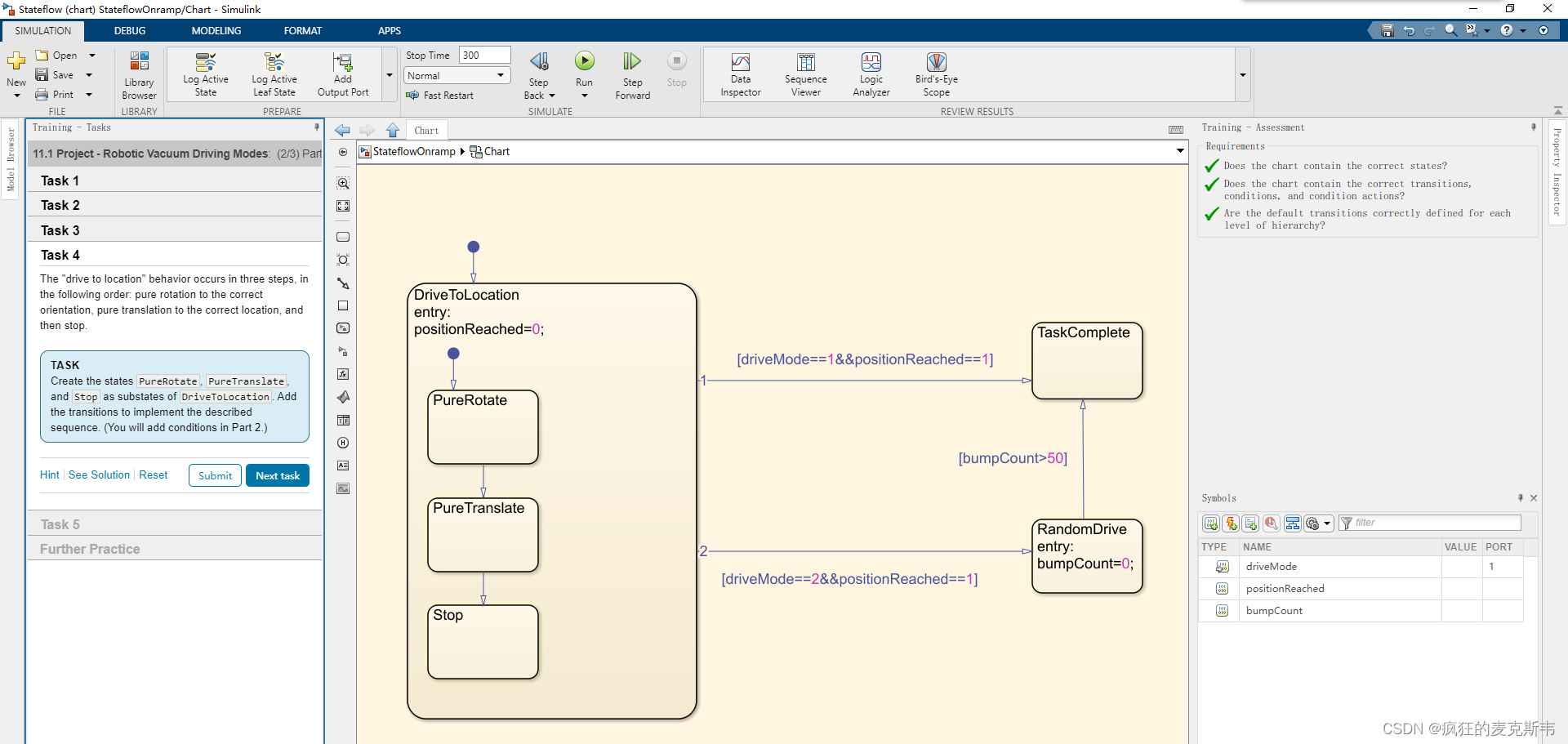
Task4(任务4)
The “drive to location” behavior occurs in three steps, in the following order: pure rotation to the correct orientation, pure translation to the correct location, and then stop.
(“drive to location”行为分为三个步骤,顺序如下:纯旋转到正确的方向,纯平移到正确的位置,然后停止。)
Create the states PureRotate, PureTranslate, and Stop as substates of DriveToLocation. Add the transitions to implement the described sequence. (You will add conditions in Part 2.)
(创建状态PureRate、PureTranslate和Stop作为DriveToLocation的子状态。添加转换以实现所描述的序列。(您将在第2部分中添加条件。))
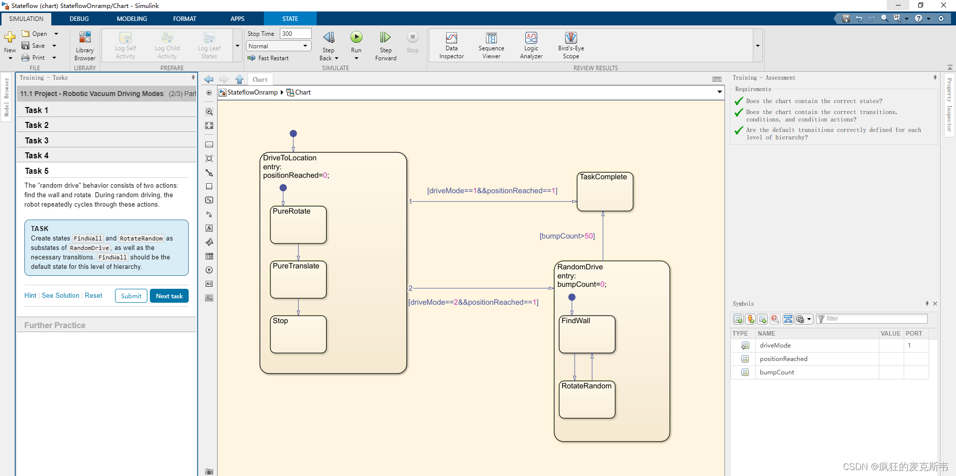
Task5(任务5)
The “random drive” behavior consists of two actions: find the wall and rotate. During random driving, the robot repeatedly cycles through these actions.
(“随机驱动”行为由两个动作组成:找到墙和旋转。在随机驾驶过程中,机器人会重复这些动作。)
Create states FindWall and RotateRandom as substates of RandomDrive, as well as the necessary transitions. FindWall should be the default state for this level of hierarchy.
(创建状态FindWall和RotateRandom作为RandomDrive的子状态,以及必要的转换FindWall应该是此层次结构级别的默认状态。)
Part2
Task1(任务1)
The chart on the right contains the driving mode framework that you built in the last lesson. Now you will add specific behaviors for each state.
(右侧的图表包含您在上一课中构建的驾驶模式框架。现在,您将为每个状态添加特定的行为。)
This chart will output the commands for velocity and angular velocity. These will be passed to the Simulink model of the robot. In pure rotation, you will set velocity, v, to 0 and angular velocity, w, to 1. In pure translation, v=3 and w=0. When stopped, both values should equal 0.
(此图表将输出速度和角速度的命令。这些将被传递到机器人的Simulink模型中。在纯旋转中,将速度v设置为0,将角速度w设置为1。在纯翻译中,v=3,w=0。停止时,两个值都应等于0。)
1、Add state entry actions to PureRotate, PureTranslate, and Stop to set the appropriate values for v and w in each state.
(1、 将状态条目操作添加到PureRate、PureTranslate和Stop,以在每个状态下为v和w设置适当的值。)
2、Define the scope of v and w so that they can be passed to the Simulink model.
(2、 定义v和w的范围,以便将它们传递给Simulink模型。)
3、Add an entry action to the Stop state to set positionReached to 1.
(3、 将条目操作添加到停止状态,将位置已达到设置为1。)

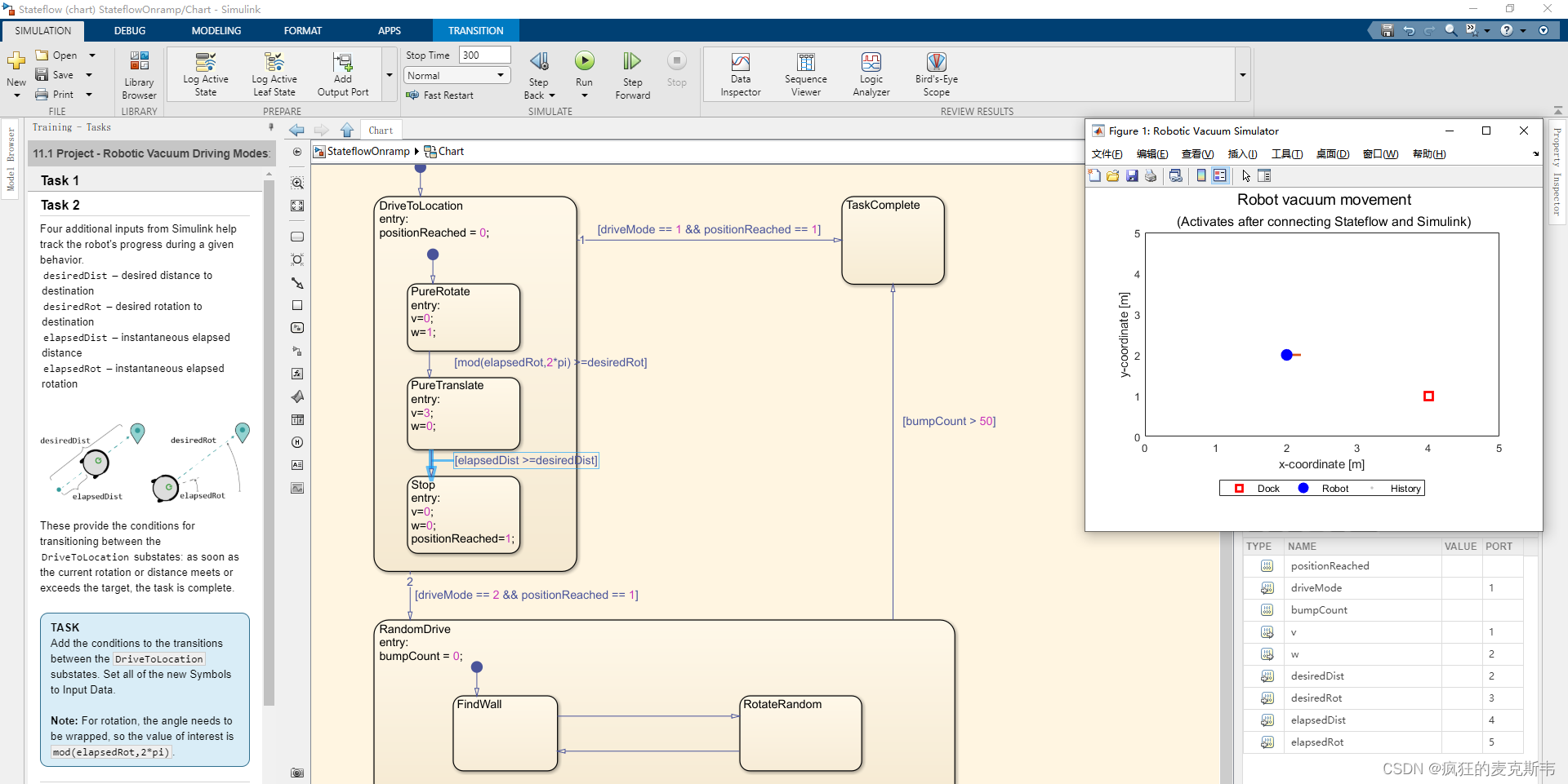
Task2(任务2)
Four additional inputs from Simulink help track the robot’s progress during a given behavior.
(来自Simulink的四个额外输入有助于跟踪机器人在给定行为过程中的进展。)
desiredDist – desired distance to destination(desiredDist–到目的地的期望距离)
desiredRot – desired rotation to destination(desiredRot–期望旋转到目的地)
elapsedDist – instantaneous elapsed distance(elapsedDist–瞬时经过距离)
elapsedRot – instantaneous elapsed rotation(elapsedRot–瞬时经过的旋转)
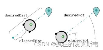
These provide the conditions for transitioning between the DriveToLocation substates: as soon as the current rotation or distance meets or exceeds the target, the task is complete.
(这些为在DriveToLocation子状态之间转换提供了条件:一旦当前旋转或距离达到或超过目标,任务就完成了。)
Add the conditions to the transitions between the DriveToLocation substates. Set all of the new Symbols to Input Data.
(将条件添加到DriveToLocation子状态之间的转换中。将所有新符号设置为“输入数据”。)
Note: For rotation, the angle needs to be wrapped, so the value of interest is mod(elapsedRot,2*pi).
(注意:对于旋转,需要包裹角度,因此感兴趣的值为mod(elapsedRot,2*pi)。)
Task3(任务3)
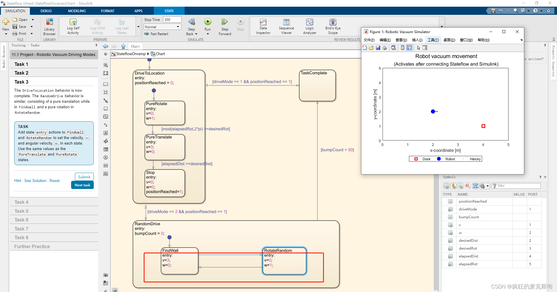
The DriveToLocation behavior is now complete. The RandomDrive behavior is similar, consisting of a pure translation while in FindWall and a pure rotation in RotateRandom.
(DriveToLocation行为现已完成。RandomDrive行为类似,包括在FindWall中的纯平移和在RotateRandom中的纯旋转。)
Add state entry actions to FindWall and RotateRandom to set the velocity, v, and angular velocity, w, in each state. Use the same values as the PureTranslate and PureRotate states.
(将状态条目操作添加到FindWall和RotateRandom,以设置每个状态下的速度v和角速度w。使用与PureTranslate和PureRate状态相同的值。)
Task4(任务4)
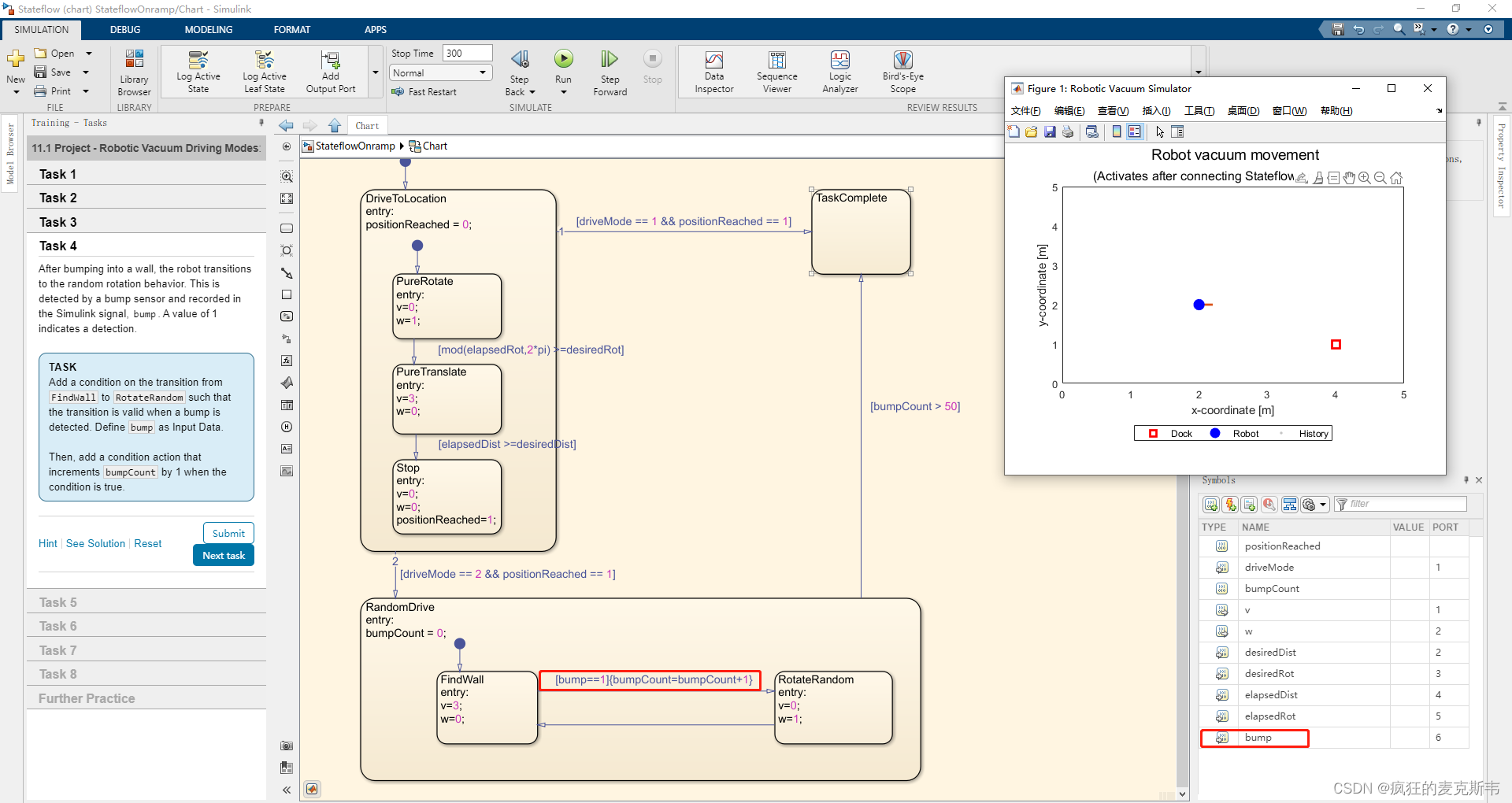
After bumping into a wall, the robot transitions to the random rotation behavior. This is detected by a bump sensor and recored in the Simulink signal, bump. A value of 1 indicates a detetion.
(撞到墙上后,机器人转变为随机旋转行为。这是由碰撞传感器检测到的,并记录在Simulink信号中,即碰撞。值为1表示一个detetion。)
Add a condition on the transition from FindWall to RotateRandom such that the transition is vaild when a bump is detected. Define bump as Input Data.
(在从FindWall到RotateRandom的转换上添加一个条件,以便在检测到凹凸时转换有效。将bump定义为输入数据。)
Then, add a condition action that increments bumpCount by 1 when the condition is true.
(然后,添加一个条件操作,当条件为true时,将bumpCount递增1。)
Task5(任务5)
To achieve a random rotation, you can create a random variable, tRotate, that represents the amount of time to remain in the rotation state. You can then use this value as the argument in a temporal operator to determine when to transition back to the FindWall state.
(要实现随机旋转,可以创建一个随机变量tRotate,该变量表示保持旋转状态的时间量。然后,您可以将该值用作时态运算符中的参数,以确定何时转换回FindWall状态。)
Add the following MATLAB command to the RotateRandom entry action. The command generates a random number between 2.5 and 4.
(将以下MATLAB命令添加到RotateRandom条目操作中。该命令生成一个介于2.5和4之间的随机数。)
tRotate = rand(1) * 1.5+2.5;
Use tRotate and a temporal operator to transition from RotateRandom to FindWall after 2.5-4 seconds. Remember to Resolve undefined symbols to define tRotate as Local Data.
(使用tRotate和时态操作符在2.5-4秒后从RotateRandom转换到FindWall。请记住解析未定义的符号以将t旋转定义为本地数据。)

Task6(任务6)
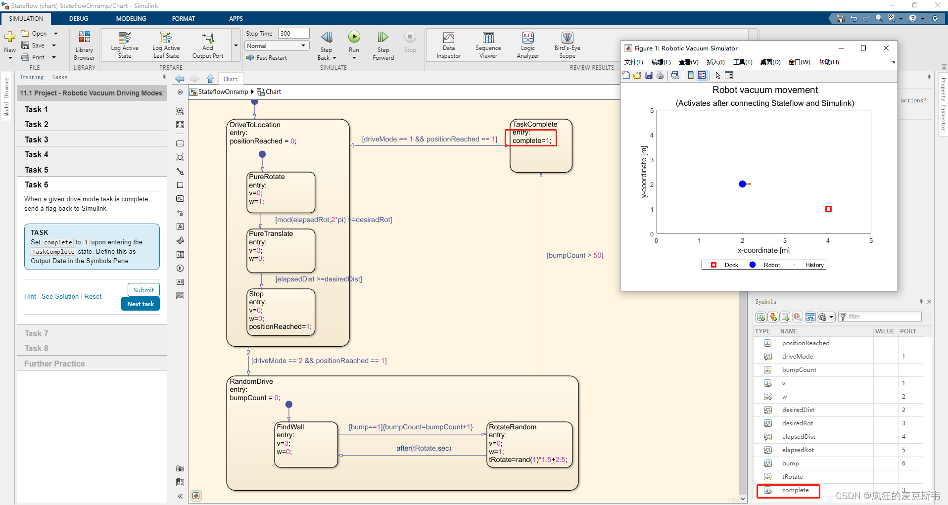
When a given drive mode task is complete, send a flag back to Simulink.
(当给定的驱动模式任务完成时,将一个标志发送回Simulink。)
Set complete to 1 upon entering the TaskComplete state. Define this as Output Data in the Symbols Pane.
(进入任务完成状态时,将完成设置为1。在符号窗格中将其定义为输出数据。)
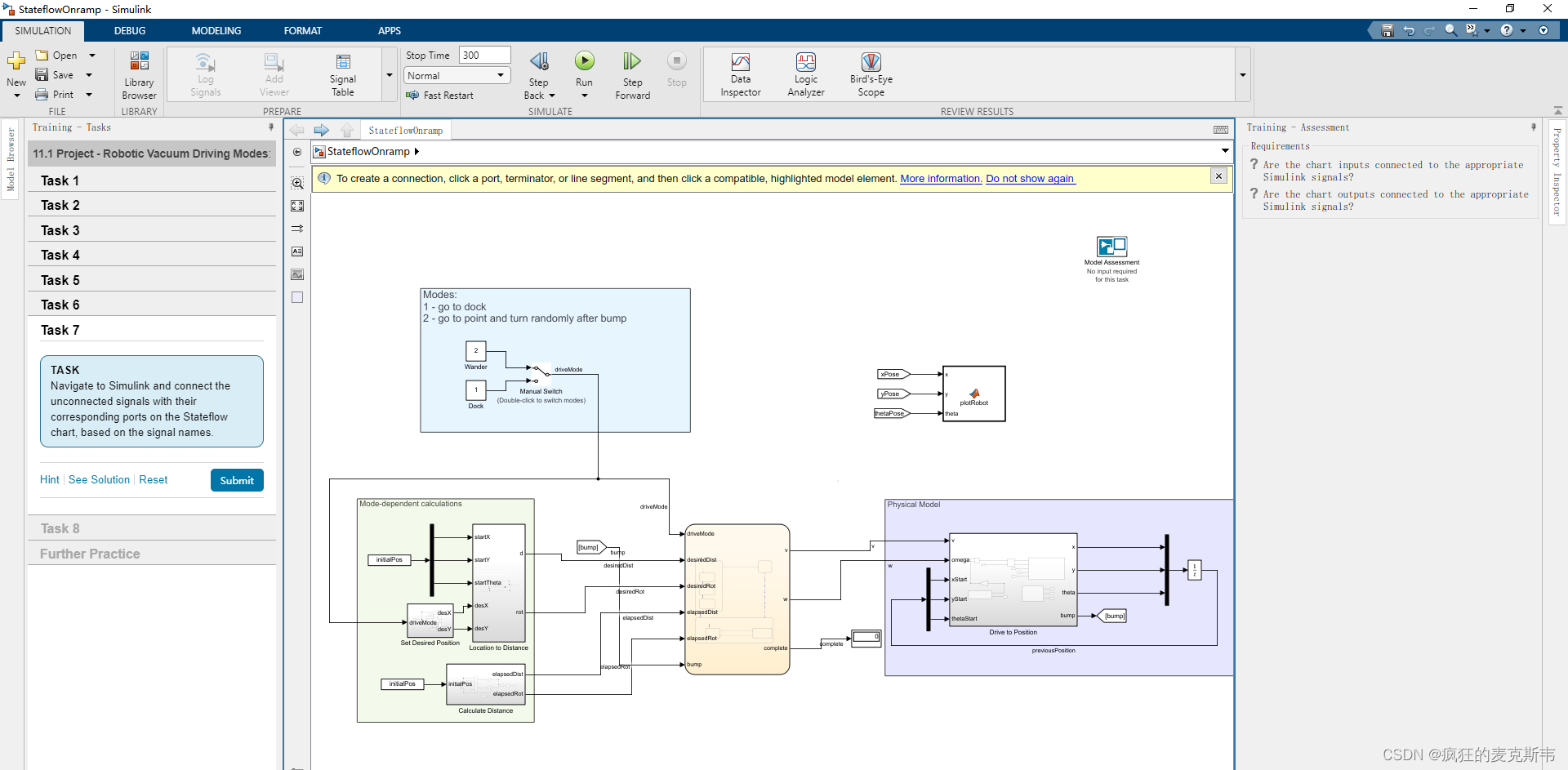
Task7(任务7)
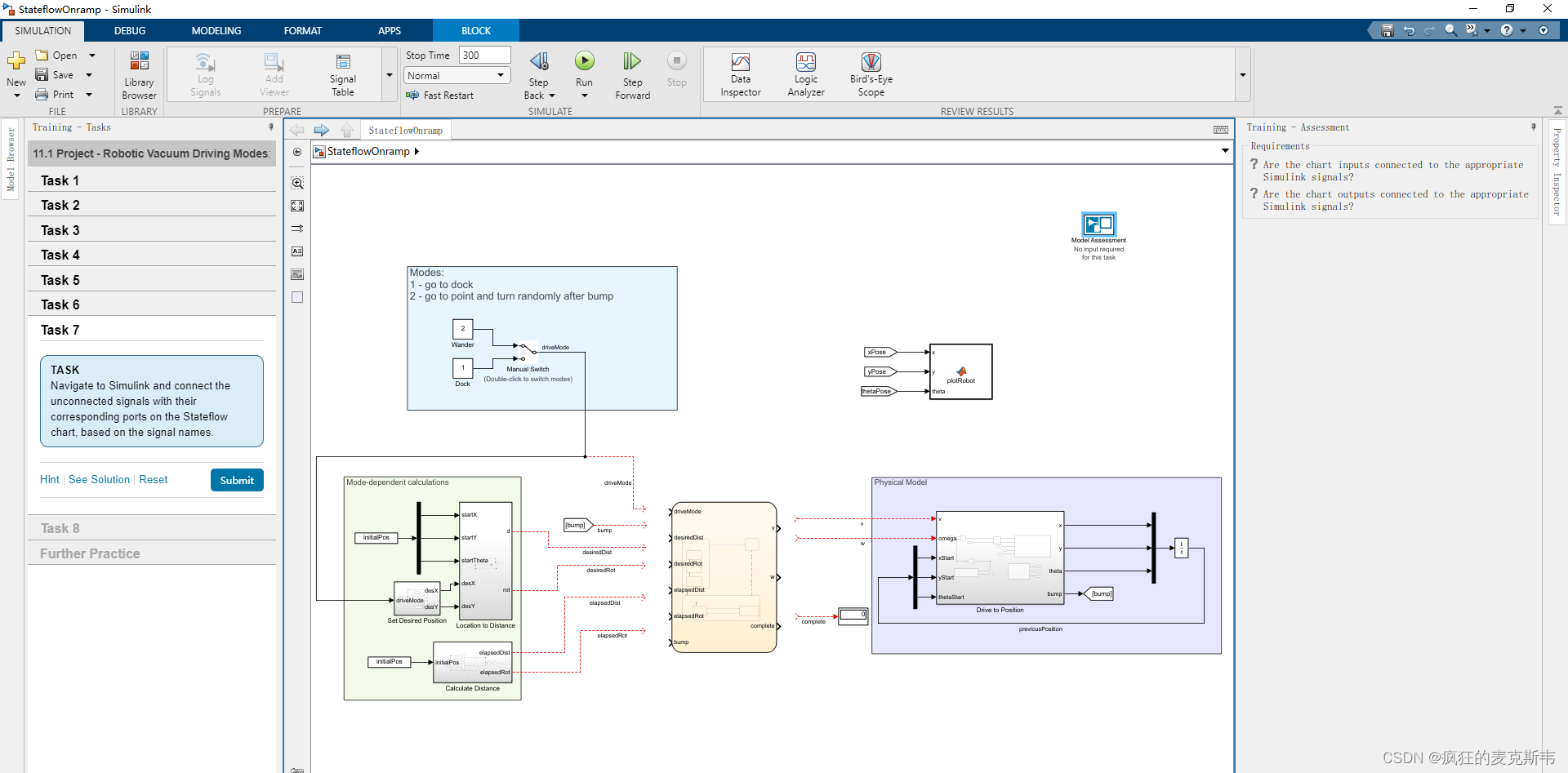
Navigate to Simulink and connect the unconnected signals with their corresponding ports on the Stateflow chart, based on the signal names.
(导航到Simulink,并根据信号名称将未连接的信号与其状态流程图上的相应端口连接起来。)
Task8(任务8)
Finally, to uncross the signals, change the port order in the Stateflow chart.
(最后,要取消交叉信号,请更改Stateflow图表中的端口顺序。)
Change the input port of bump to port 2, so the resulting input port order is as follows.
(将bump的输入端口更改为端口2,因此生成的输入端口顺序如下。)
1 – driveMode
2 – bump
3 – desiredDist
4 – desiredRot
5 – elapsedDist
6 – elapsedRot
