Introduction(介绍)
Stateflow supports the construction of flow charts: stateless models of logic patterns such as decision trees and iterative loops. Flow charts can visually represent complex algorithms in a format that is easy to read, and Stateflow allows you to create and run flow charts without having to translate them into text code. In addition, Stateflow flow charts can be used to describe advanced rules for transitioning between states.
(Stateflow支持构建流程图:逻辑模式的无状态模型,如决策树和迭代循环。流程图可以以易读的格式直观地表示复杂的算法,Stateflow允许您创建和运行流程图,而无需将其转换为文本代码。此外,状态流流程图可用于描述状态之间转换的高级规则。)
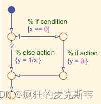
Flow charts are built using two kinds of graphical elements available in Stateflow: transitions and junctions. You are already familiar with transitions—conditional pathways represented by arrows. Junctions are nodes that divide the pathways into segments, represented by circles O . They can provide additional branches along a decision pathway. For example, transitions and junctions can be used to model an if-else statement.
(流程图是使用Stateflow中可用的两种图形元素构建的:转换和连接。您已经熟悉由箭头表示的转换条件路径。交叉点是将路径划分为段的节点,用圆圈表示。它们可以沿着决策路径提供额外的分支。例如,转换和连接可以用于对if-else语句进行建模。)
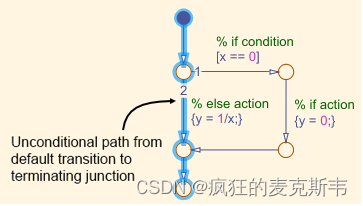
When a Stateflow chart consists of only a flow chart, the flow chart needs to(当状态流程图仅由流程图组成时,流程图需要)
·Have a single, default transition.(有一个单一的默认转换。)
·Converge at a single, terminating junction.(在一个单独的端接路口汇合。)
There should also be an unconditional transition from every junction that represents a decision point. In other words, provide an else statement for any if or if-elseif decision tree; or a default case for a switch statement.
(从代表决策点的每个结点也应该有一个无条件的过渡。换句话说,为任何if或if elseif决策树提供else语句;或switch语句的默认情况。)
Flow charts can also be used as parts of state machines to model more complex transitions or state actions. You will learn more about this in the Graphical Functions lesson.
(流程图也可以用作状态机的一部分,以对更复杂的转换或状态操作进行建模。您将在“图形函数”课程中了解有关此方面的更多信息。)
Pattern Wizard(图案向导)
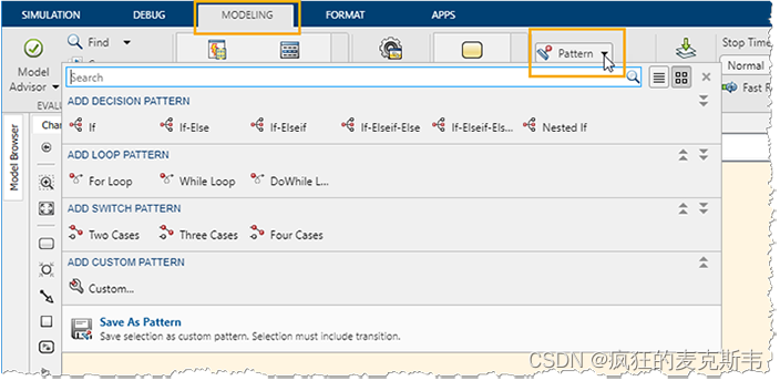
Stateflow provides a Pattern Wizard to simplify creating common flow charts. These patterns include(Stateflow提供了一个模式向导来简化创建通用流程图的过程。这些模式包括)
Decision: if, if-else, and nested if decision patterns.(决策:if、if else和嵌套if决策模式。)
Loop: for, while, and do-while loop patterns.(循环:for、while和do while循环模式。)
Switch: switch patterns with up to four cases.(开关:最多四个案例的开关模式。)
Custom: custom patterns that you saved for later reuse.(自定义:保存以供以后重用的自定义图案。)
To insert a pattern, open a chart. Navigate to the Modeling tab. Click Pattern and choose the pattern you wish to create.(要插入图案,请打开图表。导航到“建模”选项卡。单击“图案”,然后选择要创建的图案。)
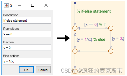
A dialog box will appear. Here, you can enter the commands for the appropriate branches of your pattern. The resulting flow chart will automatically apply the correct syntax—comments, conditions, or condition actions—for a given field.
(将出现一个对话框。在这里,您可以为模式的相应分支输入命令。生成的流程图将自动为给定字段应用正确的语法注释、条件或条件操作。)
Simulink Interaction(Simulink交互)
TASK1(任务1)
In this lesson, you will build an iterator that wraps back to 1 when the index reaches a maximum value. The chart will have two inputs: previous and maximum index values. It will output the next index value.
( 在本课中,您将构建一个迭代器,当索引达到最大值时,该迭代器将返回到1。该图表将有两个输入:以前的索引值和最大索引值。它将输出下一个索引值。)
For example, for a maximum index of 3, and a starting value of 1, the chart inputs and outputs are as follows.(例如,对于最大索引3和起始值1,图表输入和输出如下。)
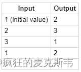
The decision logic is given below.(决策逻辑如下所示。)
index = prevIndex + 1;
if index > maxIndex
index = 1;
end
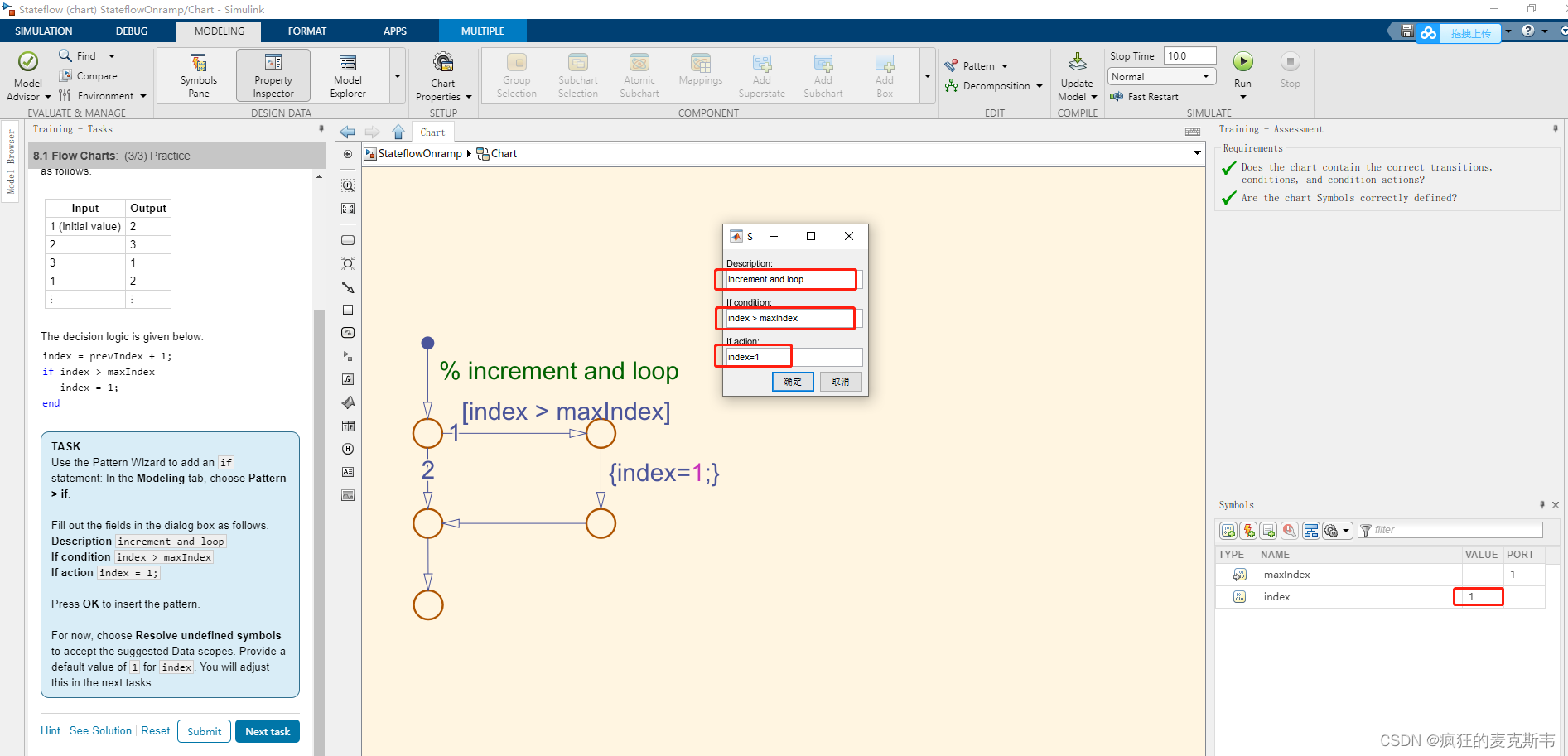
Use the Pattern Wizard to add an if statement: In the Modeling tab, choose Pattern > if.
Fill out the fields in the dialog box as follows.
Description increment and loop
If condition index > maxIndex
If action index = 1;
Press OK to insert the pattern.
For now, choose Resolve undefined symbols to accept the suggested Data scopes. Provide a default value of 1 for index. You will adjust this in the next tasks.
TASK2(任务2)
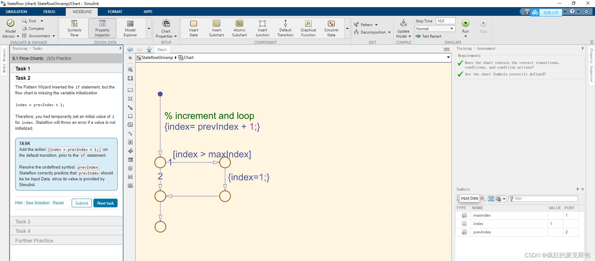
The Pattern Wizard inserted the if statement, but the flow chart is missing the variable initialization
(模式向导插入了if语句,但流程图缺少变量初始化)
index = prevIndex + 1;
Therefore, you had temporarily set an initial value of 1 for index. Stateflow will throw an error if a value is not initialized.(因此,您暂时将索引的初始值设置为1。如果某个值未初始化,则Stateflow将引发错误。)
Add the action {index = prevIndex + 1;} on the default transition, prior to the if statement.
(在if语句之前,在默认转换上添加操作{index=prevIndex+1;}。)
Resolve the undefined symbol, prevIndex. Stateflow correctly predicts that prevIndex should be be Input Data, since its value is provided by Simulink.
(解析未定义的符号prevIndex。Stateflow正确地预测了prevIndex应该是输入数据,因为它的值是由Simulink提供的。)
TASK3(任务3)
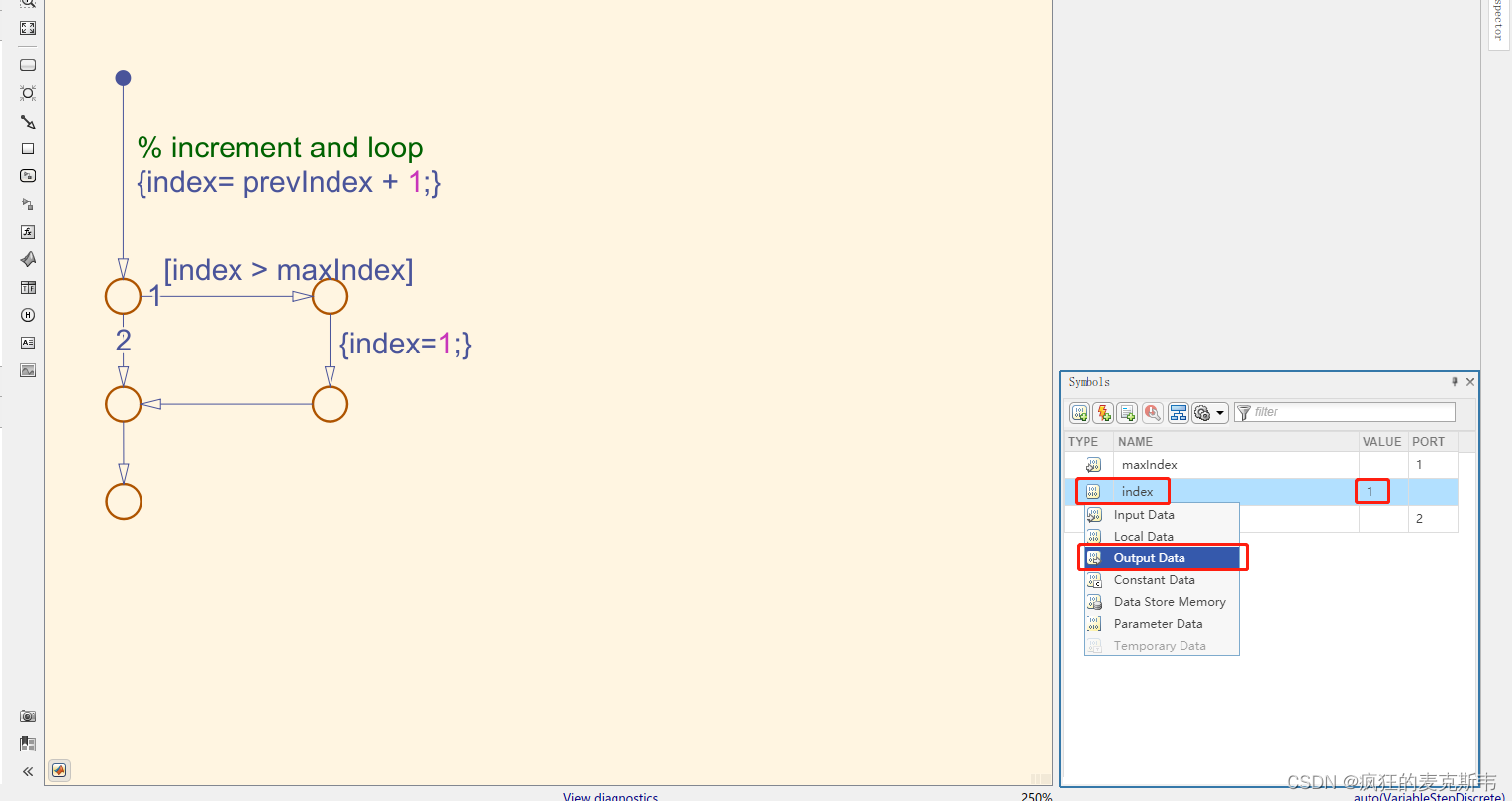
Now that index is properly defined at each step, it no longer needs an initial value. In addition, index is the desired output of this flowchart, so its Data scope should not be Local Data.
(现在,索引在每一步都得到了正确的定义,它不再需要初始值。此外,索引是此流程图所需的输出,因此其数据范围不应为本地数据。)
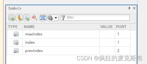
Use the Symbols Pane to change the Data scope of index to Output Data.
(使用“符号窗格”将索引的“数据”范围更改为“输出数据”。)
Clear the initial value from the Value field.
(清除“值”字段中的初始值。)
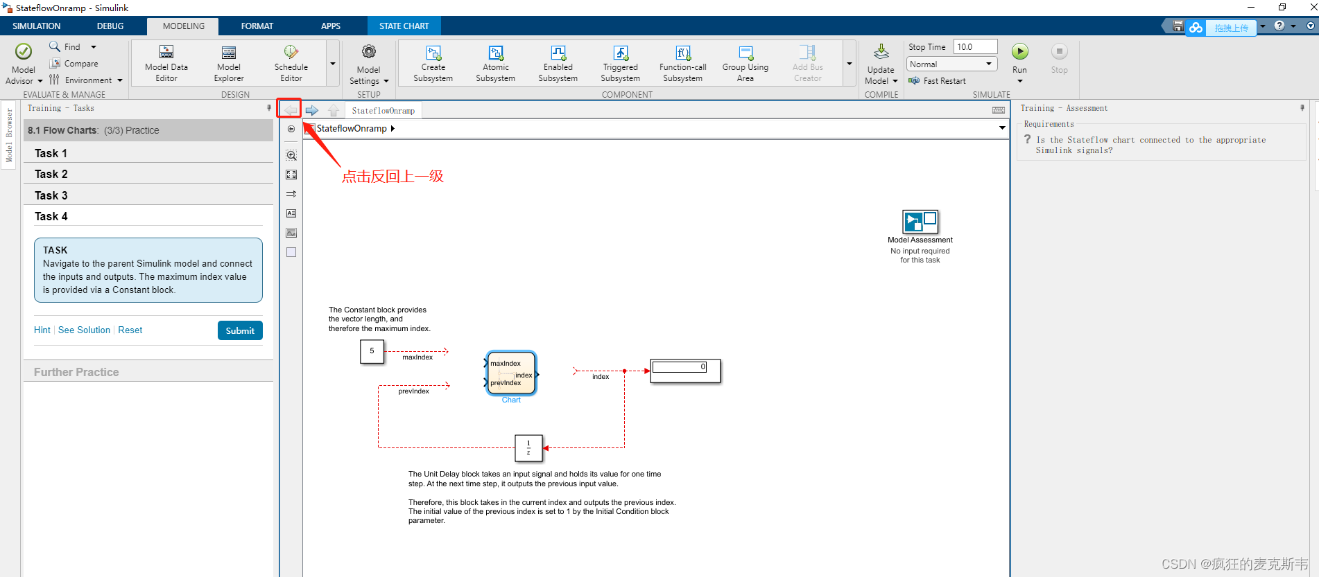
TASK4(任务4)
Navigate to the parent Simulink model and connect the inputs and outputs. The maximum index value is provided via a Constant block.
(导航到父Simulink模型并连接输入和输出。最大索引值通过Constant块提供。)
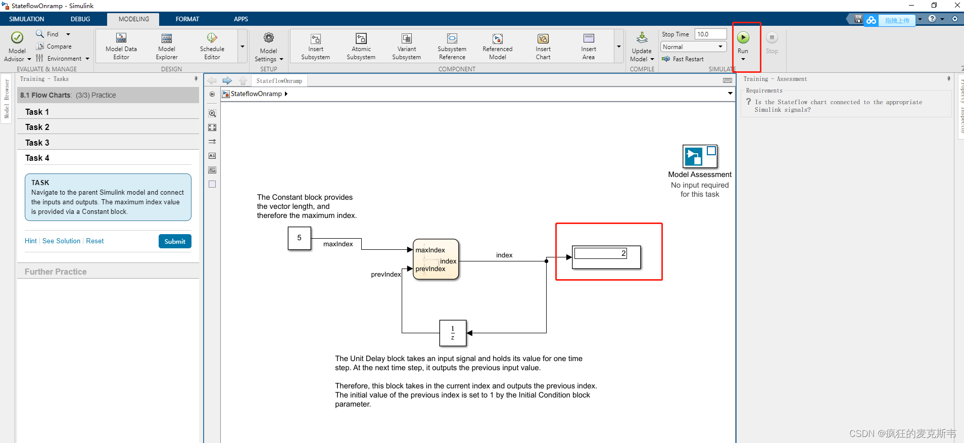
连接完成后,点击Run,查看变化。