1.While executing a command (when acrosshair is attached to the cursor),auto panning becomes active by touchingany edge of the Design Window. Press the SHIFT key while auto panning toincrease the panning speed. Auto panning speed is configured in the Auto PanOptions section of the Graphical Editingpage in thePreferencesdialog(Tools » Schematic Preferences).Auto panning can also be turned off here.
Note : The auto panoptions apply in both the schematic and the schematic library editors. Sinceyou work at a much higher zoom level in the library editor window area, you mayfind that auto panning moves the view too quickly. If this is the case you mayprefer to disable auto panning and pan with the right mouse button (refer to 3.1.1.2).
这里说的是当我们的光标变为十字箭头的时候,再移动鼠标的时候,屏幕所显示的区域便会随着鼠标的移动而变化了。在原理图中看不出屏幕变化所带来的影响,但是在库文件编辑环境中就会不一样了,我遇到过当点击一个引脚准备找个合适的地方放置的时候,发现稍微移动一下鼠标屏幕显示就会移动相当大的位置,原来认为是鼠标太灵敏了,其实是Altium自身设置的问题。
2. Textin electrical objects can be over scored, typically to indicate an active lowsignal, by adding ‘\’ after the character, e.g. R\ESET would display ‘R’ asover scored text. To overscore the entire word with a single ‘\’ character,enable theSingle ‘\’ Negation option in the Schematic– Graphical Editingpageof the Preferences dialog.
在原理图编辑环境下的 electrical objects
对话框中的Net Label和Port想要在显示字母上方添加横线,系统默认是在每个字母后边加‘\’则每个字母在显示出来的时候
‘\’便变成了每个字母上方的横线。如果我们想让整个单词上方都有一条横线,则需要在每个字母后边添加‘\’,但是通过上面的设置只要在单词的最左端加上‘\’则整个单词上方就有了横线。
3. 在原理图编辑环境下的布线。

• Pressthe shift + SPACEBAR to change the placement mode. There are Fourplacement modes as follows:
- 90 degree
- 45 degree
- any angle
- auto wire.
• The BACKSPACE key deletes the last vertex placed.
• The SPACEBAR is used to change the current placement modes start andend point. This only works for 90 and 45 degrees modes.
• A wireend must fall on the connection point of an electrical object to be connectedto it. For example, the end of a wire must fall on the hot end of a pin toconnect.
• Wireshave the Auto Junction feature, which automatically inserts a Junction objectif a wire starts or ends on another wire or runs across a pin.
• To addmore vertices click and hold the left mouse button on a wire and press the INSERT Key.
• Toremove a vertex, select the vertex, right click and select Edit Wire Vertex NO. Wire properties dialog comes up in verticesmode and clickRemove.
在布线时按shift + SPACEBAR可以更换4钟布线模式,在布线模式选择90度或45度情况下,只按SPACEBAR可以改变布线开始结束情况,即90度时可以先走90度的倍数,45度时可以先走45度的度数。
对于vertex即布线过程中的端点,这里有很多过于端点的操作,现在还不知道有什么用处。
4. Selection memory
Eight selection memories areavailable in the Schematic and PCB editors, which can be used to store andrecall the selection state of up to eight sets of objects on the schematic orPCB. Select the objects you want to remember using any of the methods describedabove in Table 5, and then store them for quick recall later.
The following selection memoryoptions are available:
• Store in memory (CTRL + number 1 to 8)
• Add to memory (SHIFT + number 1 to 8)
• Recall from memory (ALT + number 1 to 8)
• Recall and Add from memory (SHIFT + ALT +number 1 to 8)
• Apply memory as a workspace filter (SHIFT +CTRL + number 1 to 8).
You can also access theselection memories using the Edit» Selection Memorysub-menu.
Alternatively, use the SelectionMemory control panel that is opened by clicking the button next to the MaskLevel button ( bottom right of the workspace), or pressingCTRL+Q. Click on aSTObutton to store a selection orRCL to recall a selection. The filtering options at thebottom of the control panel will determine how the selection is displayed.
To prevent accidentally overwritinga selection memory, enable the Confirm Selection Memory Clear option in theSchematic – Graphical Editingpage of the Preferences dialog. Selection Memory locations can be locked frombeing overwritten by checking theLockcheckbox associated with thatselection memory.
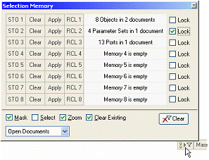
原来总是不知道这个回话框有什么作用,今天终于看到它了。主要作用是起到记忆作用,下次选择的时候可以很快的锁定。但是具体能有什么好处,还没有感受到!
5. While an object is on the cursor, the following keystrokes canbe used:
• SPACEBAR to rotate
• X key to flip around the vertical axis
• Y key to flip around the horizontal axis.
这个功能经常用,就是在鼠标拖动物体的过程中,按空格90度旋转物体,x水平旋转,y垂直旋转(前提把搜狗输入法切换到英文状态)。
6.如果想把PCB的外框原比例打印出来
File-Page Setup,在Scaling的Scale Mode项选择Scale Print。Scale:1
前提是先在高级里面把打印层设置好