前言
今天要实现的功能是超声波测距,这一功能在很多的地方都能用到,比如:在智能小车上可以添加超声波避障功能。今天需要用到SR04超声波模块,在使用这一模块的时候我很会接触到时序图。
一、SR04超声波模块
模块如图所示:
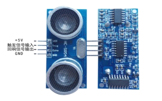
模块有四个引脚
VCC 供 5V电源,
GND 为地线,
TRIG 触 发 控 制 信 号 输入,本次学习接入的引脚是PB6
ECHO 回响信号输出,本次学习接入的引脚是PE6
二、使用步骤
1.查看SR04产品手册
在产品手册我们除了可以看 到上面的引脚示意图还可以看到一张时序图,如下图所示:
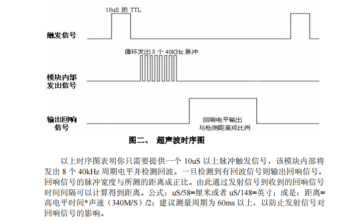
我们需要根据时序图来使用超声波模块获取测量的距离,首先我们需要读懂时序图。
我们需要了解时序图需要从上到下,从左到右来解读,这样我们把时序图分为四个部分,如图所示:
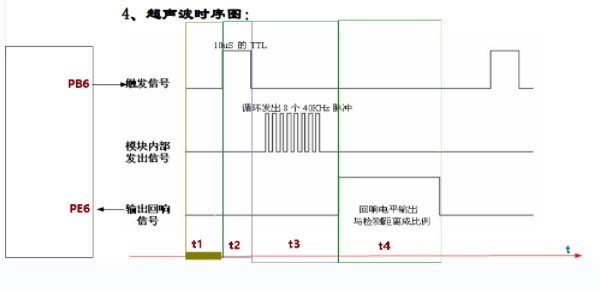
从图中我们可以知道触发信号(PB6)初始电平为低电平,在设置高电平大概10us,我们程序需要超过10us这样才能保证稳定性再设置为低电平,这时引脚PB6经历了低电平、高电平10us、低电平模块内部就会发出8个40KHz脉冲,再经历8个脉冲后PE6引脚就会检测到一个高电平,我们需要计算高电平的时间,通过手册中:
距离= 高电平时间*声速(340M/S)/2的公式中340M/S可换算成大概每9微秒3毫米,这样我们就可以得到实际距离。
2.引脚初始化
代码如下:
void sr04_init(void)
{


   //使能PB6时钟
	RCC_AHB1PeriphClockCmd(RCC_AHB1Periph_GPIOB, ENABLE);
	//使能PE6时钟
	RCC_AHB1PeriphClockCmd(RCC_AHB1Periph_GPIOE, ENABLE);
	//配置PB6为输出模式
	GPIO_InitStructure.GPIO_Pin = GPIO_Pin_6;
	GPIO_InitStructure.GPIO_Mode = GPIO_Mode_OUT;//复用功能模式
	GPIO_InitStructure.GPIO_OType = GPIO_OType_PP;//推挽输出
	GPIO_InitStructure.GPIO_Speed = GPIO_Speed_100MHz;//100MHz
	GPIO_InitStructure.GPIO_PuPd = GPIO_PuPd_UP;//上拉
	GPIO_Init(GPIOB, &GPIO_InitStructure);//初始化
	//配置PE6为输入模式
	GPIO_InitStructure.GPIO_Pin = GPIO_Pin_6;
	GPIO_InitStructure.GPIO_Mode = GPIO_Mode_IN;//复用功能模式
	GPIO_InitStructure.GPIO_OType = GPIO_OType_PP;//推挽输出
	GPIO_InitStructure.GPIO_Speed = GPIO_Speed_100MHz;//100MHz
	GPIO_InitStructure.GPIO_PuPd = GPIO_PuPd_UP;//上拉
	GPIO_Init(GPIOE, &GPIO_InitStructure);//初始化

	PBout(6)=0;
}
3.获取测量距离
int32_t sr04_get_distance(void)
{


	int32_t t=0;
	int32_t d=0;
	//PB6高电平10us以上
	PBout(6)=1;
	delay_us(20);
	PBout(6)=0;
	//等待回响信号高电平
	while(PEin(6)==0)
	{


		t++;
		delay_us(1);
		if(t>=100000)
		{


			return -1;
		}
	}
	t=0;
	while(PEin(6))
	{


		t++;
		delay_us(9);//3毫米距离
		if(t>=10000)
		{


			return -2;
		}
	}
	t=t/2;
	d=3*t;
	return d;

}
4.完整代码
#include "stm32f4xx.h"                  // Device header
#include "sys.h"
#include "stdio.h"


static GPIO_InitTypeDef  GPIO_InitStructure;
static USART_InitTypeDef USART_InitStructure;
static NVIC_InitTypeDef NVIC_InitStructure;
static uint16_t d;


struct __FILE {

     int handle; /* Add whatever you need here */ };
FILE __stdout;
FILE __stdin;
int fputc(int ch, FILE *f)
{


	USART_SendData(USART1,ch);
	while(USART_GetFlagStatus(USART1,USART_FLAG_TXE)==RESET);

	return ch;
}


void delay_ms(uint32_t n)
{


	while(n--)
	{


		SysTick->CTRL = 0; // Disable SysTick
		SysTick->LOAD = (168000)-1; // Count from 255 to 0 (256 cycles)
		SysTick->VAL = 0; // Clear current value as well as count flag
		SysTick->CTRL = 5; // Enable SysTick timer with processor clock
		while ((SysTick->CTRL & 0x00010000)==0);// Wait until count flag is set
	}

	SysTick->CTRL = 0; // Disable SysTick
}
void delay_us(uint32_t n)
{


	while(n--)
	{


		SysTick->CTRL = 0; // Disable SysTick
		SysTick->LOAD = (168)-1; // Count from 255 to 0 (256 cycles)
		SysTick->VAL = 0; // Clear current value as well as count flag
		SysTick->CTRL = 5; // Enable SysTick timer with processor clock
		while ((SysTick->CTRL & 0x00010000)==0);// Wait until count flag is set
	}

	SysTick->CTRL = 0; // Disable SysTick
}

void usart1_init(uint32_t band)
{


	//打开硬件时钟
	RCC_AHB1PeriphClockCmd(RCC_AHB1Periph_GPIOA, ENABLE);

	//打开串口1硬件时钟
	RCC_APB2PeriphClockCmd(RCC_APB2Periph_USART1, ENABLE);

	//配置PA9和PA10为服用功能
	GPIO_InitStructure.GPIO_Pin = GPIO_Pin_9|GPIO_Pin_10;
	GPIO_InitStructure.GPIO_Mode = GPIO_Mode_AF;//复用功能模式
	GPIO_InitStructure.GPIO_OType = GPIO_OType_PP;//推挽输出
	GPIO_InitStructure.GPIO_Speed = GPIO_Speed_100MHz;//100MHz
	GPIO_InitStructure.GPIO_PuPd = GPIO_PuPd_UP;//上拉
	GPIO_Init(GPIOA, &GPIO_InitStructure);//初始化


	//将PA9和PA10引脚连接到串口1的硬件
	GPIO_PinAFConfig(GPIOA,GPIO_PinSource9,GPIO_AF_USART1);
	GPIO_PinAFConfig(GPIOA,GPIO_PinSource10,GPIO_AF_USART1);

	//配置串口1相关参数:波特率、无校验位、8位数位、1位停止位
	USART_InitStructure.USART_BaudRate = band;					//波特率
    USART_InitStructure.USART_WordLength = USART_WordLength_8b; //8位数据位
    USART_InitStructure.USART_StopBits = USART_StopBits_1;		//1个停止位
    USART_InitStructure.USART_Parity = USART_Parity_No;			//无奇偶检验
    USART_InitStructure.USART_HardwareFlowControl = USART_HardwareFlowControl_None; //无硬件流控制
    USART_InitStructure.USART_Mode = USART_Mode_Rx | USART_Mode_Tx;	//允许收发数据

    USART_Init(USART1, &USART_InitStructure);

	//配置串口1的中断触发方法 接收一个字节触发中断
	USART_ITConfig(USART1, USART_IT_RXNE, ENABLE);
	//配置串口1的中断优先级

	NVIC_InitStructure.NVIC_IRQChannel = USART1_IRQn;
	NVIC_InitStructure.NVIC_IRQChannelPreemptionPriority = 0;
	NVIC_InitStructure.NVIC_IRQChannelSubPriority = 0;
	NVIC_InitStructure.NVIC_IRQChannelCmd = ENABLE;
	NVIC_Init(&NVIC_InitStructure);

	//使能串口1工作
	USART_Cmd(USART1,ENABLE);
}

void sr04_init(void)
{


   //使能PB6时钟
	RCC_AHB1PeriphClockCmd(RCC_AHB1Periph_GPIOB, ENABLE);
	//使能PE6时钟
	RCC_AHB1PeriphClockCmd(RCC_AHB1Periph_GPIOE, ENABLE);
	//配置PB6为输出模式
	GPIO_InitStructure.GPIO_Pin = GPIO_Pin_6;
	GPIO_InitStructure.GPIO_Mode = GPIO_Mode_OUT;//复用功能模式
	GPIO_InitStructure.GPIO_OType = GPIO_OType_PP;//推挽输出
	GPIO_InitStructure.GPIO_Speed = GPIO_Speed_100MHz;//100MHz
	GPIO_InitStructure.GPIO_PuPd = GPIO_PuPd_UP;//上拉
	GPIO_Init(GPIOB, &GPIO_InitStructure);//初始化
	//配置PE6为输入模式
	GPIO_InitStructure.GPIO_Pin = GPIO_Pin_6;
	GPIO_InitStructure.GPIO_Mode = GPIO_Mode_IN;//复用功能模式
	GPIO_InitStructure.GPIO_OType = GPIO_OType_PP;//推挽输出
	GPIO_InitStructure.GPIO_Speed = GPIO_Speed_100MHz;//100MHz
	GPIO_InitStructure.GPIO_PuPd = GPIO_PuPd_UP;//上拉
	GPIO_Init(GPIOE, &GPIO_InitStructure);//初始化

	PBout(6)=0;
}

int32_t sr04_get_distance(void)
{


	int32_t t=0;
	int32_t d=0;
	//PB6高电平10us以上
	PBout(6)=1;
	delay_us(20);
	PBout(6)=0;
	//等待回响信号高电平
	while(PEin(6)==0)
	{


		t++;
		delay_us(1);
		if(t>=100000)
		{


			return -1;
		}
	}
	t=0;
	while(PEin(6))
	{


		t++;
		delay_us(9);//3毫米距离
		if(t>=10000)
		{


			return -2;
		}
	}
	t=t/2;
	d=3*t;
	return d;

}


int main(void)
{


	int32_t d;

	RCC_AHB1PeriphClockCmd(RCC_AHB1Periph_GPIOF, ENABLE);//使能GPIOF时钟

	//GPIOF9,F10初始化设置
	GPIO_InitStructure.GPIO_Pin = GPIO_Pin_9;
	GPIO_InitStructure.GPIO_Mode = GPIO_Mode_OUT;//复用功能模式
	GPIO_InitStructure.GPIO_OType = GPIO_OType_PP;//推挽输出
	GPIO_InitStructure.GPIO_Speed = GPIO_Speed_100MHz;//100MHz
	GPIO_InitStructure.GPIO_PuPd = GPIO_PuPd_UP;//上拉
	GPIO_Init(GPIOF, &GPIO_InitStructure);//初始化


	GPIO_SetBits(GPIOF,GPIO_Pin_9);


	usart1_init(115200);
	sr04_init();


	while(1)
	{


		d=sr04_get_distance();
		if(d>0)
		{


			if(d>=20 && d<=4000)
			{


				printf("distance=%dmm\r\n",d);
			}
		}
		delay_ms(1000);
	}
}


void USART1_IRQHandler(void)
{


	//检查标志位
	if(USART_GetITStatus(USART1,USART_IT_RXNE)==SET)
	{


		d=USART_ReceiveData(USART1);

		printf(d+"");
		//清空标志位
		USART_ClearITPendingBit(USART1,USART_IT_RXNE);
	}


}
5.运行效果
我们通过串口将测量的距离打印出来,效果如下图所示:
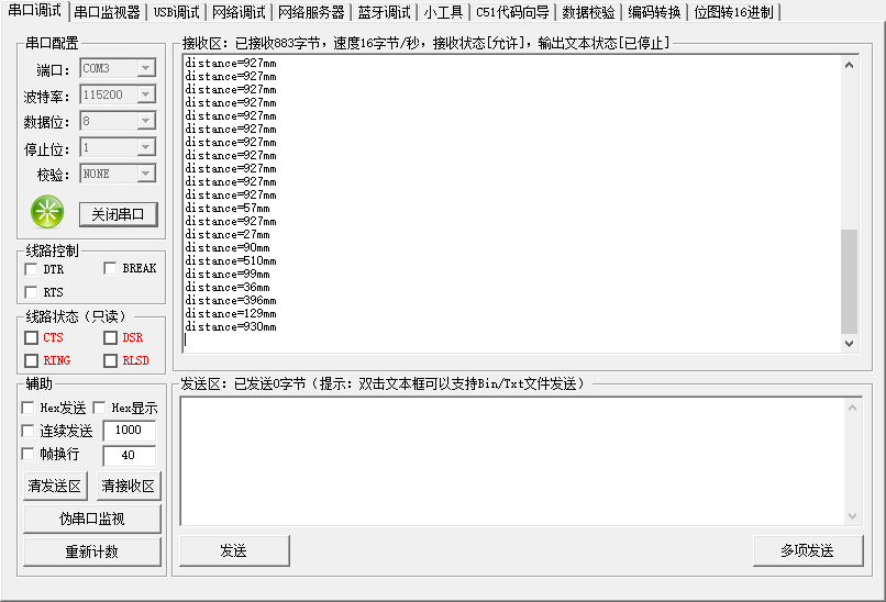
测量的距离可以通过串口成功的打印出来!