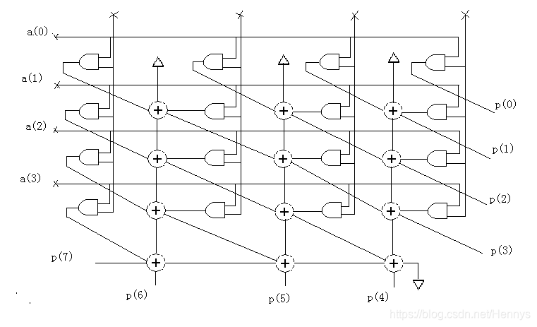
上图是4位并行乘法器的电路结构图
设计代码
`timescale 1ns / 1ps
//
// Company:
// Engineer:
//
// Create Date: 2020/08/07 13:53:37
// Design Name:
// Module Name: and_2
// Project Name: 定义二输入与门电路

//


//two input and_gate
module and_2(a,b,y);
input a,b;
output y;
assign y=a&b;
endmodule
`timescale 1ns / 1ps
//
// Company:
// Engineer:
//
// Create Date: 2020/08/07 13:54:19
// Design Name:
// Module Name: one_adder
// Project Name: 定义一位全加器电路

//


//one input adder
module one_adder(a,b,cin,s,cout);
input a,b,cin;
output s,cout;
assign s=a^b^cin;
assign cout=(a&b)|(a&cin)|(b&cin);
endmodule
以上两个模块是需要用到的单元电路,然后对于乘法器的结构按层编写电路的设计代码
`timescale 1ns / 1ps
//
// Company:
// Engineer:
//
// Create Date: 2020/08/07 13:28:21
// Design Name:
// Module Name:
// Project Name:
//
//


//parallel multiplier
module top_row(a,b,sout,cout,p);
input a;
input [3:0] b;
output [2:0] sout,cout;
output p;
and_2 q1(
         .a    (a      ),
         .b    (b[3]   ),
         .y    (sout[2]));
and_2 q2(
         .a    (a      ),
         .b    (b[2]   ),
         .y    (sout[1]));
and_2 q3(
         .a    (a      ),
         .b    (b[1]   ),
         .y    (sout[0]));
and_2 q4(
         .a    (a      ),
         .b    (b[0]   ),
         .y    (p      ));

assign cout=0;
endmodule

module mid_row(a,b,sout,cout,p,cin,sin);
input a;
input [3:0] b;
input [2:0] sin,cin;
output [2:0] sout,cout;
output p;
wire [2:0] and_out;

and_2 u1(
         .a   (a         ),
         .b   (b[3]      ),
         .y   (sout[2])  );
and_2 u2(
         .a   (a         ),
         .b   (b[2]      ),
         .y   (and_out[2]));
and_2 u3(
         .a   (a         ),
         .b   (b[1]      ),
         .y   (and_out[1]));
and_2 u4(
         .a   (a         ),
         .b   (b[0]      ),
         .y   (and_out[0]));

one_adder q1(
             .a   (sin[2]     ),
             .b   (cin[2]     ),
             .cin (and_out[2] ),
             .s   (sout[1]    ),
             .cout(cout[2]    ));
one_adder q2(
             .a   (sin[1]     ),
             .b   (cin[1]     ),
             .cin (and_out[1] ),
             .s   (sout[0]    ),
             .cout(cout[1]    ));
one_adder q3(
             .a   (sin[0]     ),
             .b   (cin[0]     ),
             .cin (and_out[0] ),
             .s   (p    ),
             .cout(cout[0]    ));
endmodule

module lower_row(sin,cin,p);
input [2:0] sin,cin;
output [3:0] p;
wire [2:0] local;
assign local[0]=0;
one_adder q1(
             .a    (sin[0]   ),
             .b    (cin[0]   ),
             .cin  (local[0] ),
             .s    (p[0]     ),
             .cout (local[1] ));
one_adder q2(
             .a    (sin[1]   ),
             .b    (cin[1]   ),
             .cin  (local[1] ),
             .s    (p[1]     ),
             .cout (local[2] ));
one_adder q3(
             .a    (sin[0]   ),
             .b    (cin[2]   ),
             .cin  (local[2] ),
             .s    (p[2]     ),
             .cout (p[3]     ));
endmodule
测试代码
`timescale 1ns / 1ps
//
// Company:
// Engineer:
//
// Create Date: 2020/08/07 14:48:06
// Design Name:
// Module Name: Test1450
// Project Name: 并行乘法器测试代码
// Target Devices:
// Tool Versions:
// Description:
//
// Dependencies:
//
// Revision:
// Revision 0.01 - File Created
// Additional Comments:
//
//


module Test1450;
reg [3:0] a;
reg [3:0] b;
wire [7:0] result;
main_multip u1(
               .a      (a      ),
               .b      (b      ),
               .result (result ));

initial begin
           a=0;b=0;
   #100;   a=3;b=5;
   #100;   a=8;b=7;
   #100;   a=15;b=15;
   #100;   a=11;b=13;
   #100;   a=4;b=0;
end
endmodule
并行乘法器电路代码
`timescale 1ns / 1ps
//
// Company:
// Engineer:
//
// Create Date: 2020/08/07 14:15:00
// Design Name:
// Module Name: main_multip
// Project Name:
// Target Devices:
//
//

module main_multip(a,b,result);
input [3:0] a,b;
output [7:0] result;
wire [2:0] c0,c1,c2,c3;
wire [2:0] s0,s1,s2,s3;
top_row q1(.a    (a[0]     ),
           .b    (b        ),
           .sout (s0       ),
           .cout (c0       ),
           .p    (result[0]));

mid_row q2(.a    (a[1]     ),
           .b    (b        ),
           .sin  (s0       ),
           .cin  (c0       ),
           .sout (s1       ),
           .cout (c1       ),
           .p    (result[1]));
mid_row q3(.a    (a[2]     ),
           .b    (b        ),
           .sin  (s1       ),
           .cin  (c1       ),
           .sout (s2       ),
           .cout (c2       ),
           .p    (result[2]));
mid_row q4(.a    (a[3]     ),
           .b    (b        ),
           .sin  (s2       ),
           .cin  (c2       ),
           .sout (s3       ),
           .cout (c3       ),
           .p    (result[3]));

lower_row q5(
           .sin  (s3       ),
           .cin  (c3       ),
           .p    (result[7:4]));
endmodule
仿真波形图如下:

上面的代码最好是每一块都单独建立一个文件编写,最后编译完成之后软件会自动划分文件的上下层次,main_multip这个文件是主电路文件,一定要设置成顶层文件!