Grasping based on UR5
This project is based on the Robot Operate System and Simulate on it. The Robot Arm we used is universal robot 5 and the simulate world is build by Gazebo. Follow I will introduce and record how to complete this project and share some figure which is the captured in the build process.
Part 1: Build the Gazebo Word && Simulate UR5 in it.
We can create UR5 from the document in official website and what we need to build is the world to simulate in. Because of Gazebo which have excellent API for ROS and have a great performance in simulate, we need to create a grasping environment for this project. At first, we need to download the model from the github website and the guide for it can be found in the Google search. After download the model for gazebo, we start to create simulation world for it and save the world file named by the end of .world. Then, we add the model of UR5 in the world by launch file. The launch file can be written as :
<launch>
  <arg name="paused" default="true"/>
  <arg name="gui" default="true"/>
  <arg name="sim" default="true" />
  <arg name="debug" default="false"/>
  <!-- startup simulated world -->
  <include file="$(find gazebo_ros)/launch/empty_world.launch">
    <!--arg name="world_name" default="worlds/empty.world"/-->
    <arg name="world_name" default="$(find ur5_single_arm_tufts)/worlds/ur5_cubes.world"/>
    <arg name="paused" value="$(arg paused)"/>
    <arg name="gui" value="$(arg gui)"/>
  </include>
  <!-- send robot urdf to param server -->
  <param name="robot_description" command="$(find xacro)/xacro --inorder '$(find ur5_single_arm_tufts)/urdf/ur5_single_arm.urdf.xacro'"/>
  <!-- push robot_description to factory and spawn robot in gazebo -->
  <node name="spawn_gazebo_model" pkg="gazebo_ros" type="spawn_model"
        args="-urdf -param robot_description -model robot -z 0.90
              -J shoulder_lift_joint -2.0
              -J elbow_joint 1.0"
        output="screen" />

</launch>
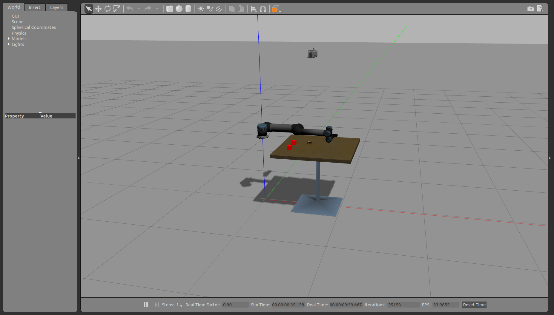
The first part of it is the argument which will be used bellow and the second part is about the launch file run the gazebo in the ROS. In this launch file, we need to define which world to simulate mainly in the gazebo and other arguments. The next part is about the UR5 robot description and using the xacro to explain the file for it and using the spawn to push it to factory and spawn robot in the gazebo. The running result show in the bellow figure.
| Figure 1.1: The Gazebo World 1 (error) | Figure 1.2: The Gazebo World 2 (accurate) |
|---|---|
 |
 |
Part 2: Provide Vision and Gripper for the End Effector
For the grasping work, the end effector need the Gripper at fist and the problem is how to get the object position which can be coped by camera. The gripper in this project is used open source project named robotq_85_gripper. And the camera is used kinetic depth camera and the provision by Gazebo plugin. The gazebo provides ROS interface for simulating cameras such as wge100_camera by publishing the Camera Info and image ROS messages as described in sensor messages.
At this part, we will review a simple RGB camera attached to the end of the UR5 pendulum arm. The first elements of this block are an extra link and joint added to the URDF file that represents the camera. We are just using a simple red box to represent the camera, though typically you could see a mesh file for a better representation.
<xacro:property name="camera_link" value="0.005" />
<xacro:property name="height3" value="0.0" />
<xacro:property name="axel_offset" value="0.0" />

<joint name="camera_joint" type="fixed">
	<axis xyz="0 1 0" />
    <origin xyz="${camera_link*2} 0 ${height3 - axel_offset*2}" rpy="0 0 0"/>
    <parent link="gripper_finger1_inner_knuckle_link"/>
    <child link="camera_link"/>
</joint>
<link name="camera_link">
	<collision>
    	<origin xyz="0 0 0" rpy="0 0 0"/>
      	<geometry>
    <box size="${camera_link} ${camera_link} ${camera_link}"/>
      	</geometry>
    </collision>
    <visual>
      <origin xyz="0 0 0" rpy="0 0 0"/>
      <geometry>
    <box size="${camera_link} ${camera_link} ${camera_link}"/>
      </geometry>
    </visual>
</link>
From the program, we can know that the camera joint was fixed by the parent joint named gripper_finger1_inner_knuckle_link which is the end effector of UR5. And we should be able to launch the UR5 and see a red box attached to the end of the arm. Next we will review the Gazebo plugin that gives us the camera functionality and publishes the image to a ROS message. In the UR5 we have been following the convertion of putting Gazebo elements in the common.gazebo.xacro file.
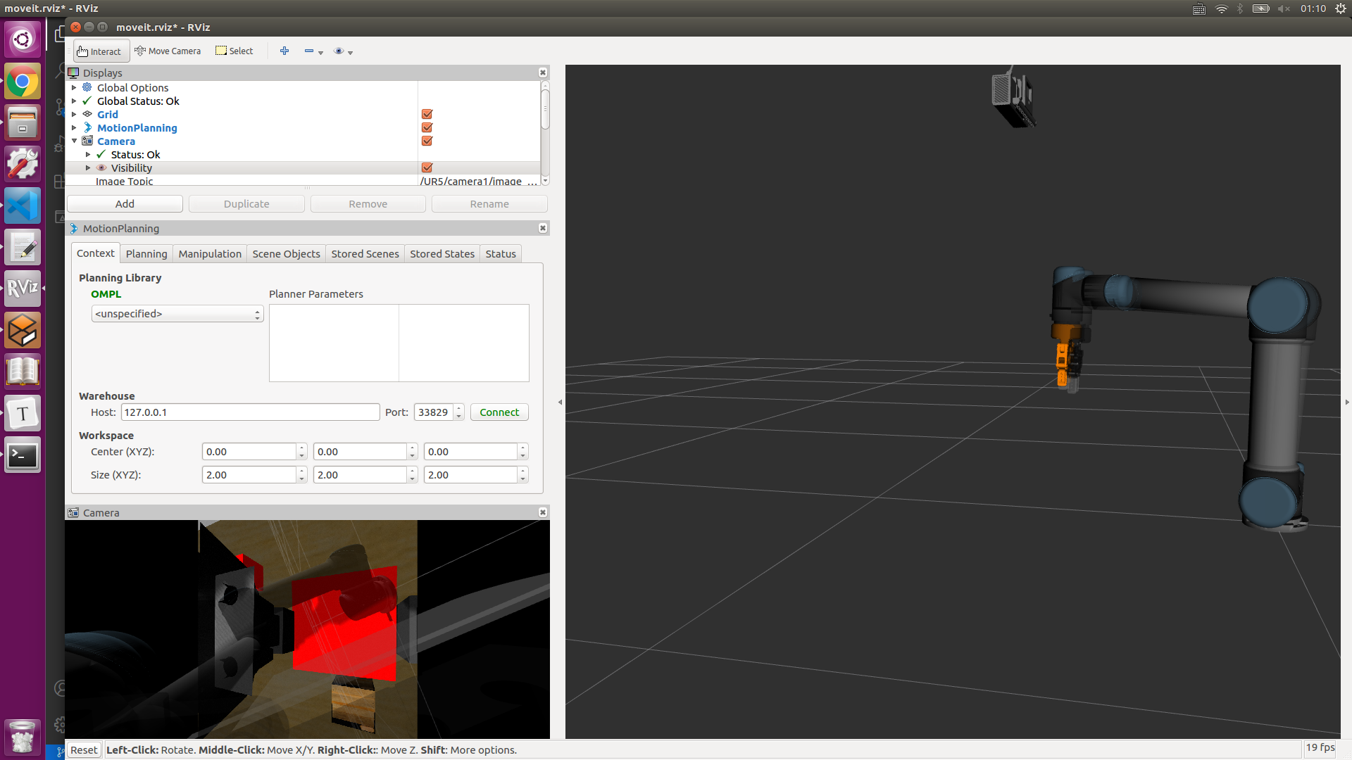
After all above of it, the image from the camera can be subscribed in Rviz. The image show the occasion that the manipulator grasp the red box. The left image show that the surrounding captured by monocular camera and based on the first camera we can add the other camera which can achieve binocular camera with the first. The right image show that the binocular camera that the top one is the left one and other is the right one.
| Fig 2.1: The Monocular Camera in the End Effector | Fig 2.2: The Binocular Camera with two exclusive Camera |
|---|---|
 |
 |
Part 3: Gazebo ROS Control
This section will introduce ROS Control which is consist of the one for controlling the UR5 and the other for controlling gripper. In the above launch file, we already add this two control package in it and both of them can be found in the UR5 official document and gripper project document.
The file path of controller package for UR5 is /ur_gazebo/launch/controller_utils.launch and the other for gripper is robotiq_85_gazebo/launch/controller_utils.launch. There are also some configuration file which need to define the control coefficient. So this part of launch file is written as follows:
<include file="$(find ur_gazebo)/launch/controller_utils.launch"/>
<include file="$(find robotiq_85_gazebo)/launch/controller_utils.launch">

<rosparam file="$(find ur_gazebo)/controller/arm_controller_ur5.yaml" command="load"/>
<rosparam file="$(find robotiq_85_gazebo)/controller/gripper_controller_robotiq.yaml" command="load"/>
<node name="arm_controller_spawner" pkg="controller_manager" type="controller_manager" args="spawn arm_controller gripper" respawn="false" output="screen"/>
Part 4: Moveit! Setup Assistant
It has been shown in the [Moveit! official website][https://ros-planning.github.io/moveit_tutorials/doc/setup_assistant/setup_assistant_tutorial.html] and the Moveit Setup Assistant is a graphical user interface for configuring any robot for use with Moveit. Its primary function is generating a Semantic Robot Description Format(SRDF) file for your robot. Additionally, it generates other necessary configuration files for use with the Moveit pipeline. To learn more about the SRDF, you can go through the URDF/SRDF Overview page. And you need to prepare the Moveit appropriate your own ROS version.
Step 1: Start
-
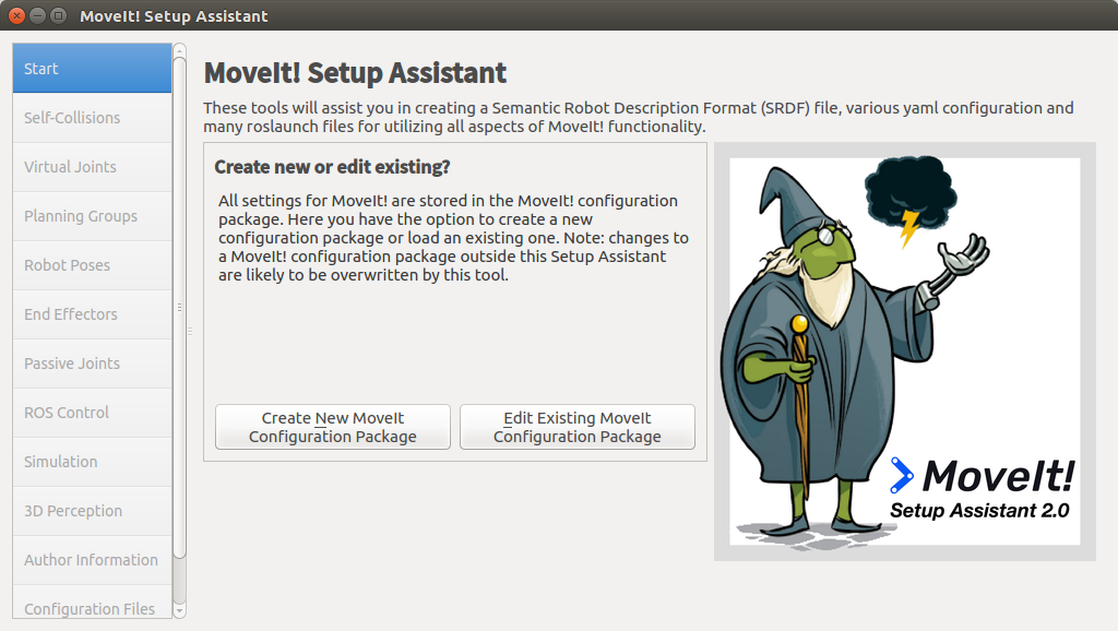
To start the Moveit Setup Assistant:
roslaunch moveit_setup_assistant setup_assistant.launch -
This will bring up the start screen with two choices: Create New Moveit Configuration Package or Edit Existing Moveit Configuration Package.
-
Click on the Create New Moveit Configuration Package button to bring up the following screen:
-
Click on the browse button and navigate to the
grasp_ws/src/ur5-gazebo-grasping/ur5_single_arm_tufts/urdf/ur5_single_arm.urdf.xacrofile installed. Choose that file and then click Load Files. The Setup Assistant will load the files.
| Fig 4.1: Start Moveit! | Fig 4.2: Load UR5 File |
|---|---|
 |
 |
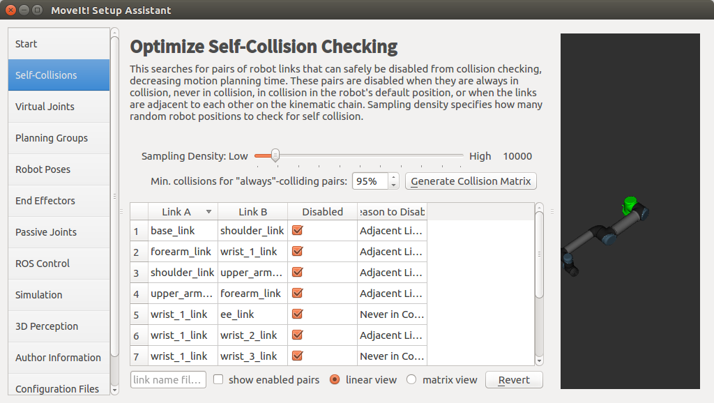
Step 2: Generate Self-Collision Matrix
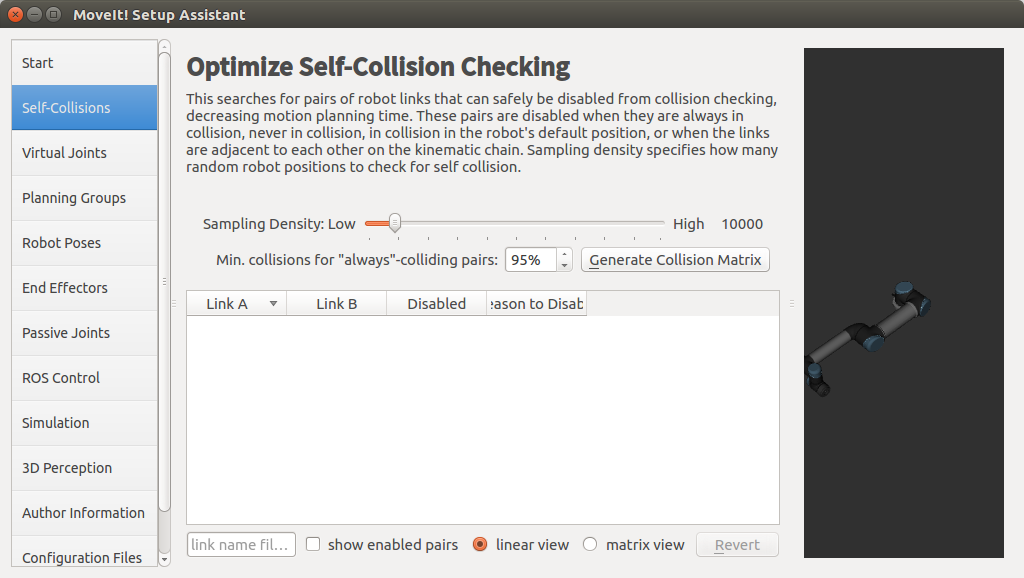
The Default Self-Collision Matrix Generator searches for pairs of links on the robot that can safely be disabled from collision checking, decreasing motion planning processing time. These pairs of links are disabled when they are always in collision, never in collision, in collision in the robot’s default position or when the links are adjacent to each other on the kinematic chain. The sampling density specifies how many random robot positions to check for self collision. higher densities require more computation time while lower densities have a higher possibility of disabling pairs that should not be disabled. The default value is 10,000 collision checks. Collision checking is done in parallel to decrease processing time.
- Click on the Self-Collision pane selector on the left-hand side and click on the Generate Collision Matrix button. The Setup Assistant will work for a few second before presenting you the results of its computation in the main tabel.
| Fig 4.3: Before Generate Self-Collision Matrix | Fig 4.4: After Generate Self-Collision Matrix |
|---|---|
 |
 |
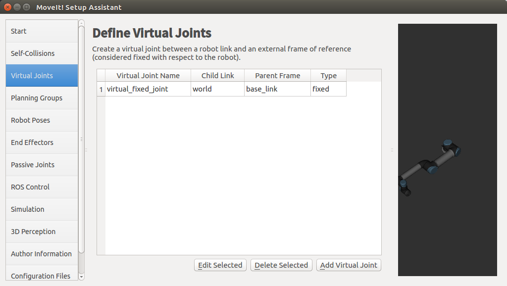
Step 3: Add Virtual Joints
Virtual joints are used primarily to attach the robot to the world. This virtual joint represents the motion of the base of the robot in a plane.
- Click on the Virtual Joints pane selector. Click on Add Virtual Joint
- Set the joint name as “virtual_fixed_joint” which is in the UR5 is the basement.
- Set the child link as “base_link” and the parent frame name as “world”.
- Click Save and you should see this screen.
| Fig 4.5: Add the Virtual Joint | Fig 4.6: Have Saved |
|---|---|
 |
 |
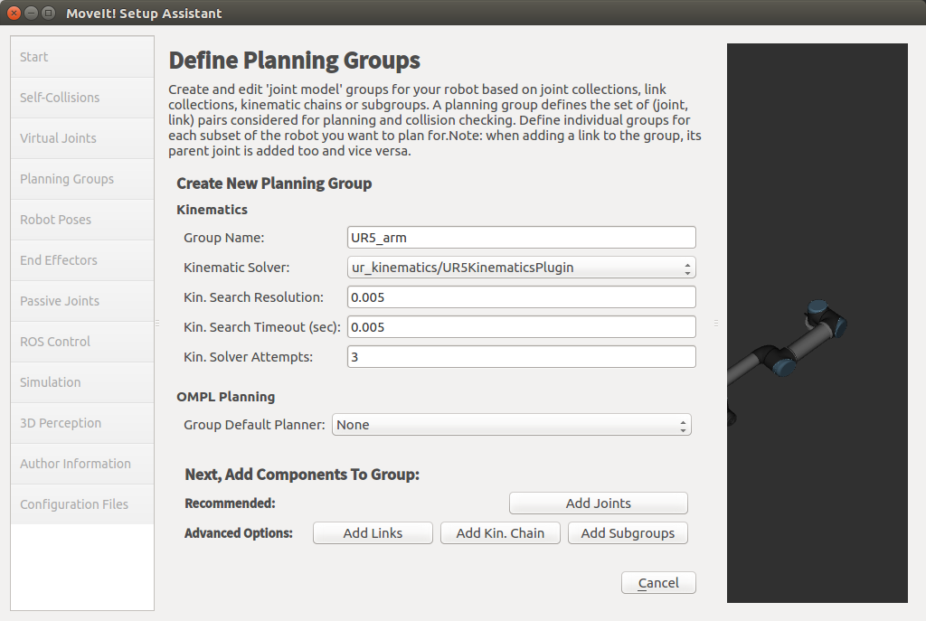
Step 4: Add Planning Groups
Planning groups are used for semantically describing different parts of your robot, such as defining what an arm is, or and end effector.
-
Click on the Planning Groups pane selector.
-
Add the arm(First add UR5 arm as a planning group)
- Enter Group Name as UR5_arm
- Choose kdl_kinematic_plugin/KDLKinematicsPlugin as the kinematics solver. But this time I used the ur_kinematics/UR5KinematicsPlugin for it which I think will be more appropriate for UR5.
- Now, click on the Add Joints button. You will see a list of joints on the left hand side. You need to choose all the joints that belong to the arm and add them to the right hand side. The joints are arranged in the order that they are stored in an internal tree structure. This makes it easy to select a serial chain of joints.
- Because the UR5 haven’t the end effector, we can choose all of the elements in the left hand side and add to the right hand side. Note: when you click any element on the left had side, that joint in the robot will be marked as red color which has been shown in the right side.
-
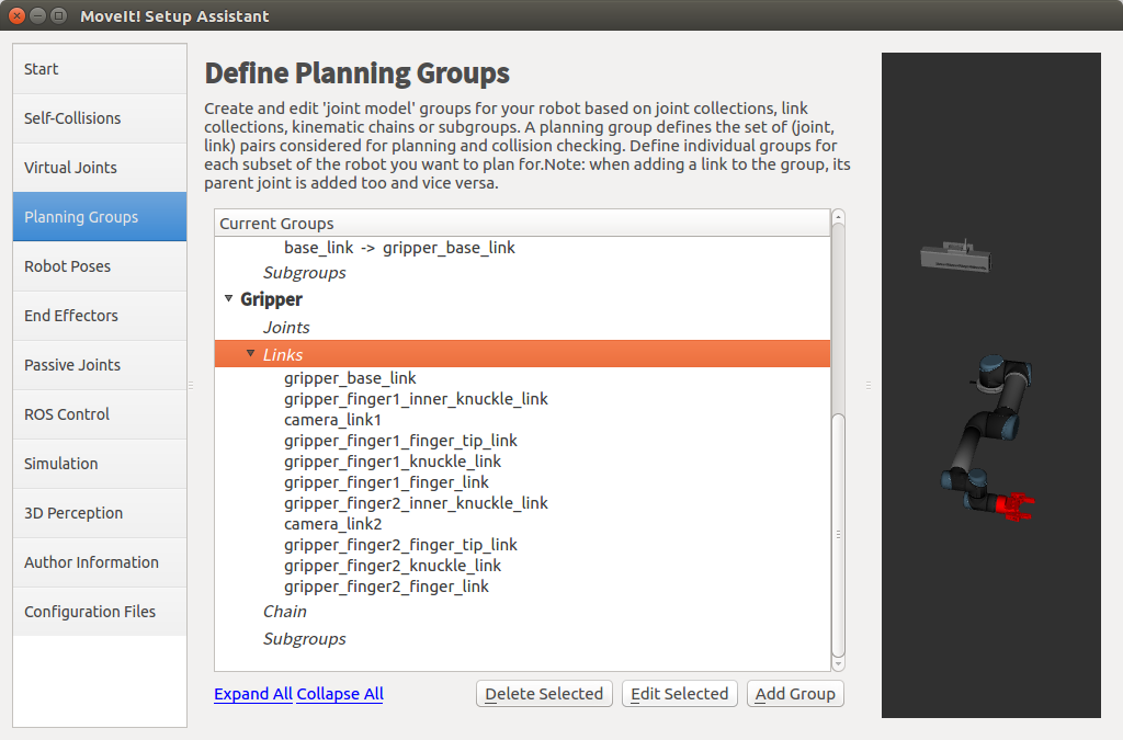
Add the Gripper(We also add a group for the end effector. NOTE that you will do this using a different procedure than adding the arm.)
- Click on the Add Group button and Enter Group Name as Gripper.
- Let Kinematic Solver stay at its default value; None.
- Let Kin.Search Resolution and Kin.Search Timeout stay at their default values.
- Click on the Add Links button. Choose the Gripper and add them to the list of Selected Links on the right hand side. And Click save.
| Fig 4.7: Add UR5_arm Group | Fig 4.8: After Add Arm and Gripper Group |
|---|---|
 |
 |
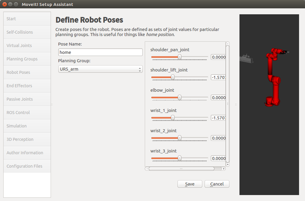
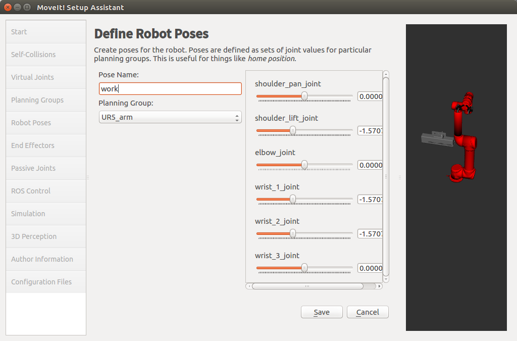
Step 5: Add Robot Poses
The Setup Assistant allows you to add certain fixed poses into the configuration. This helps if, for example, you want to define a certain position of the robot as a Home position.
- Click on the Robot Poses pane.
- Click Add Pose. Choose a name for the pose. The robot will be in its Default position where the joint values are set to the-mid-range of the allowed joint value range. Move the individual joints around until you are happy and then Save the pose. Note how poses are associated with particular groups. You can save individual poses for each group.
- IMPORTANT TIP: Try to move all the joints around. If there is something wrong with the joint limit in your URDF, you should be able to see it immediately here.
| Fig 4.9: Add a home Pose | Fig 4.10: Add a work Pose |
|---|---|
 |
 |
Step 6: Label End Effectors
We have already added the gripper of the Panda. Now, we will designate this group as a special group: end effectors. Designating this group as end effectors allows some special operations to happen on them internally.
- Click on the End Effectors pane.
- Click Add End Effector.
- Choose Gripper as the End Effector Name for the Gripper.
- Select Gripper as the End Effector Group.
| Fig 4.11: Label End Effectors | Fig 4.12: Generate the package |
|---|---|
 |
 |
After all of the steps, we need to create a file named controllers.yaml in that Moveit package. The content of that file:
controller_list:
  - name: "arm_controller"
    action_ns: follow_joint_trajectory
    type: FollowJointTrajectory
    default: true
    joints:
      - shoulder_pan_joint
      - shoulder_lift_joint
      - elbow_joint
      - wrist_1_joint
      - wrist_2_joint
      - wrist_3_joint
  - name: "gripper"
    action_ns: follow_joint_trajectory
    type: FollowJointTrajectory
    default: true
    joints:
      - gripper_finger1_joint
After configure all of above, we can run the launch file for the Rviz and Moveit and next we need to acknowledge about the move-group control.
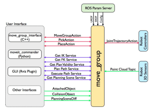
Part 5: Move-Group Control
This node serves as an integrator: pulling all the individual components together to provide a set of ROS actions and services for users to use.
| Fig 5.1: The Move-Group Node | Fig 5.2: Quick High Level Diagram |
|---|---|
 |
 |
The figure above shows the move-group node and the high-level system architecture for the primary node provided by Moveit called move-group. For using the Move-Group Control node, we can create a package by this command:
$ catkin_create_pkg ur5_manipulation control_msgs controller_manager geometry_msgs hardware_interface industrial_msgs roscpp sensor_msgs std_srvs tf trajectory_msgs ur_msgs rospy moveit_msgs moveit_ros_perception moveit_ros_planning_interface
And create file path src in this package and touch a file with c++ program language. In this file we programming as this :
#include<moveit/move_group_interface/move_group_interface.h>
#include <moveit/planning_scene_interface/planning_scene_interface.h>
#include <moveit_msgs/DisplayRobotState.h>
#include <moveit_msgs/DisplayTrajectory.h>
#include <moveit_msgs/AttachedCollisionObject.h>
#include <moveit_msgs/CollisionObject.h>
#include <vector>

int main(int argc, char **argv)
{


    ros::init(argc, argv, "UR5_test1");
    ros::AsyncSpinner spinner(1);
    spinner.start();

    moveit::planning_interface::MoveGroupInterface arm("manipulator");
    moveit::planning_interface::MoveGroupInterface gripper("gripper");
    arm.setGoalJointTolerance(0.001);
    arm.setMaxAccelerationScalingFactor(0.2);
    arm.setMaxVelocityScalingFactor(0.2);

    arm.setNamedTarget("home_j");
    arm.move();
    sleep(1);

    gripper.setNamedTarget("open");
    gripper.move();
    sleep(1);

    ros::shutdown();
    return 0;
}
And based on the running launch file, we can run this c++ file in other terminal and it will get move the robot successfully.
| GIF 1: Gazebo Simulation | GIF 2: Rviz Simulation |
|---|---|
 |
 |
I guess the reason why the blurry occur in the Rviz is that the depth data achieved by kinetic camera is the parallel plane and has a delay effect. The gripper has occluded the red box which is found in the past Rviz and there is only some part of red box which can be captured by kinetic camera.
Next time, I will try to use the multiple kinetic cameras and classify the objects captured by cameras. What’s more, it’s is a worthier project to use a robot arm to auto classify the object into the same assemble.
Thanks for the project provided by Lesson [Mobile Robot Control Experiment]
The according website: