Open MV与STM32通信 寻找色块,循迹
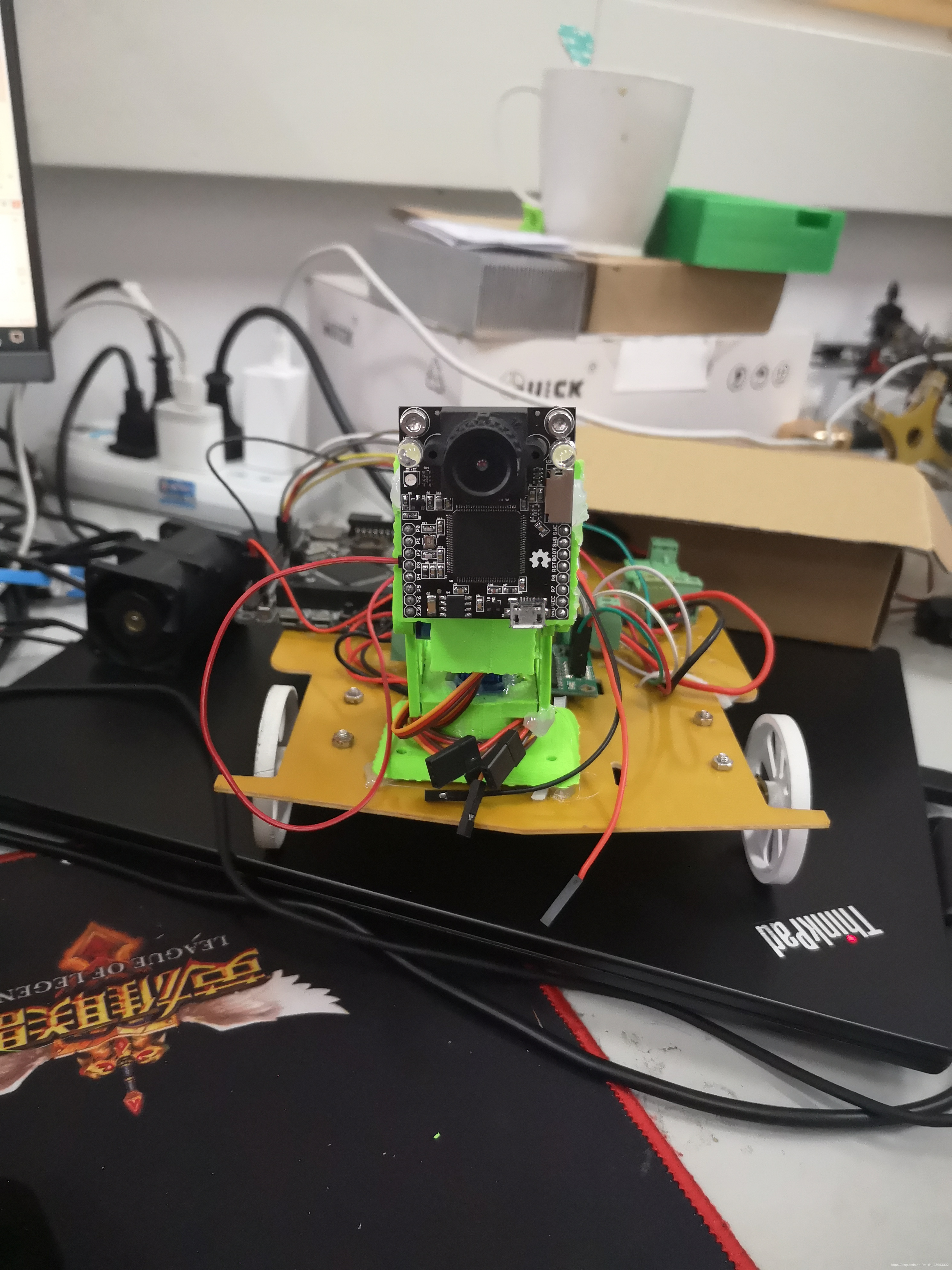
最近在实验室准备电赛,由于电赛要用到摄像头,我便开始学习openmv,学习也有一段时间了想分享一下自己的心得,自己做了一个小车来寻找色块和循迹。
OPENMV端
分享一些我自己之前找到的一些openmv资料:
https://blog.csdn.net/qq_43243338/article/details/89441756
我自己看的这篇博客和官方的资料才搞懂
1.在IDE中先需要引入一些库和写好模块的配置程序
import sensor, image, time,math,pyb
from pyb import UART,LED
import json
import ustruct

sensor.reset()
sensor.set_pixformat(sensor.RGB565)
sensor.set_framesize(sensor.QVGA)
sensor.skip_frames(time = 2000)
sensor.set_auto_gain(False) # must be turned off for color tracking
sensor.set_auto_whitebal(False) # must be turned off for color tracking
clock = time.clock()
 //关于这些配置程序的作用都可在官方文档中查到
2.openmv与stm32通信是通过串口来通信,需要在openmv上配置串口。
uart = UART(3,115200)   #定义串口3变量
uart.init(115200, bits=8, parity=None, stop=1) # init with given parameters
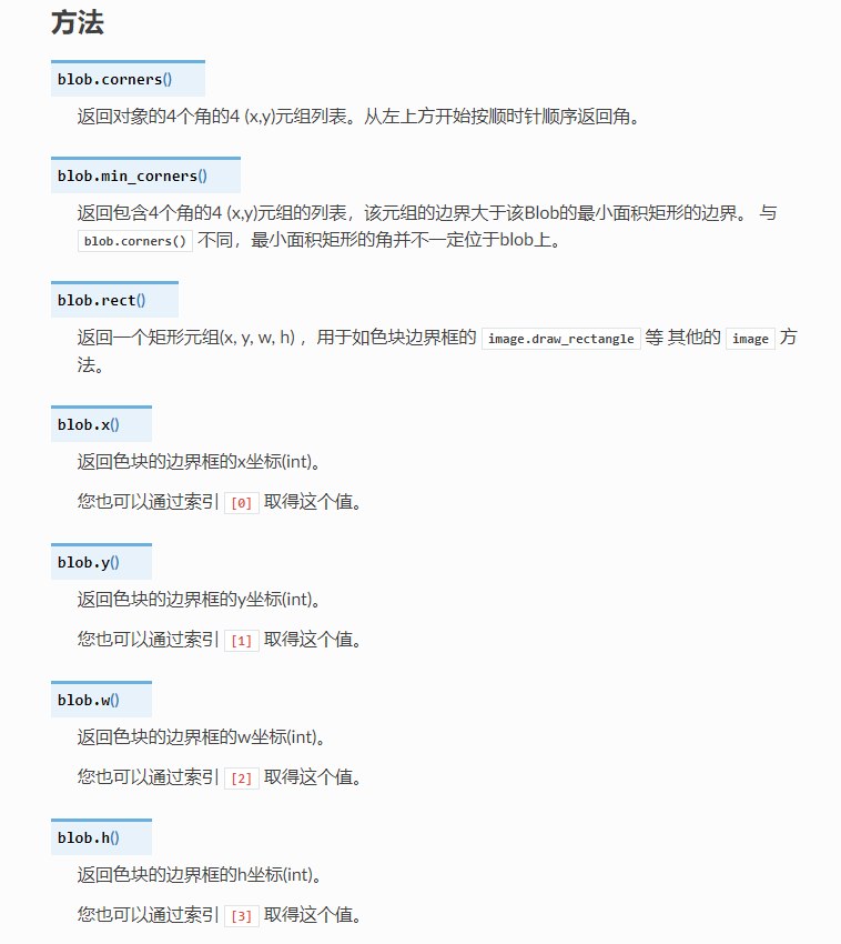
3.openmv通过micropython里的find_blobs函数来寻找色块。
官方教程:
https://www.bilibili.com/video/BV1RW411G7oy
https://book.openmv.cc/image/blob.html
看懂这些教程就能看懂这个程序
通过find_blobs函数返回的数据可得到色块的坐标等参数
find_blobs函数返回的参数:https://docs.singtown.com/micropython/zh/latest/openmvcam/library/omv.image.html#blob
:
clock.tick()
img = sensor.snapshot()
blobs = img.find_blobs([red_threshold_01]);
cx=0;cy=0;
if blobs:
#如果找到了目标颜色
max_b = find_max(blobs);
# Draw a rect around the blob.
img.draw_rectangle(max_b[0:4]) # rect
#用矩形标记出目标颜色区域
img.draw_cross(max_b[5], max_b[6]) # cx, cy
#img.draw_cross(160, 120) # 在中心点画标记
#在目标颜色区域的中心画十字形标记
cx=max_b[5];
cy=max_b[6];
cw=max_b[2];
ch=max_b[3];
4.数据发送程序
这个地方用到了ustruct.pack这个函数,要注意的是对数据的打包格式。
def sending_data(cx,cy,cw,ch):
    global uart;
    #frame=[0x2C,18,cx%0xff,int(cx/0xff),cy%0xff,int(cy/0xff),0x5B];
    #data = bytearray(frame)
    data = ustruct.pack("<bbhhhhb",              #b和h对应的是数据的格式
                   0x2C,                       #帧头1
                   0x12,                       #帧头2
                   int(cx), # up sample by 4    #数据1
                   int(cy), # up sample by 4    #数据2
                   int(cw), # up sample by 4    #数据1
                   int(ch), # up sample by 4    #数据2
                   0x5B)
    uart.write(data);   #必须要传入一个字节数组
不可直接使用串口发送数据,最好要使用帧头,否则数据会出现错误
完整程序
扫描二维码关注公众号,回复:
12442880 查看本文章

 寻找色块的中点 - By: dengbei - 周三 9月 30 2020

import sensor, image, time,math,pyb
from pyb import UART,LED
import json
import ustruct

LED_R = pyb.LED(1) # Red LED = 1, Green LED = 2, Blue LED = 3, IR LEDs = 4.
LED_G = pyb.LED(2)
LED_B = pyb.LED(3)

LED_R.on()
LED_G.on()
LED_B.on()

red_threshold_01 = ((2, 51, 11, 127, -128, 127)); #红色阈值

sensor.reset()
sensor.set_pixformat(sensor.RGB565)
sensor.set_framesize(sensor.QVGA)
sensor.skip_frames(time = 2000)
sensor.set_auto_gain(False) # must be turned off for color tracking
sensor.set_auto_whitebal(False) # must be turned off for color tracking
clock = time.clock()

LED_G.off()

uart = UART(3,115200)   #定义串口3变量
uart.init(115200, bits=8, parity=None, stop=1) # init with given parameters

def find_max(blobs):    #定义寻找色块面积最大的函数
    max_size=0
    for blob in blobs:
        if blob.pixels() > max_size:
            max_blob=blob
            max_size = blob.pixels()
    return max_blob


def sending_data(cx,cy,cw,ch):
    global uart;
    #frame=[0x2C,18,cx%0xff,int(cx/0xff),cy%0xff,int(cy/0xff),0x5B];
    #data = bytearray(frame)
    data = ustruct.pack("<bbhhhhb",              #格式为俩个字符俩个短整型(2字节)
                   0x2C,                       #帧头1
                   0x12,                       #帧头2
                   int(cx), # up sample by 4    #数据1
                   int(cy), # up sample by 4    #数据2
                   int(cw), # up sample by 4    #数据1
                   int(ch), # up sample by 4    #数据2
                   0x5B)
    uart.write(data);   #必须要传入一个字节数组

def recive_data():
    global uart
    if uart.any():
        tmp_data = uart.readline();
        print(tmp_data)


while(True):
    clock.tick()
    img = sensor.snapshot()
    blobs = img.find_blobs([red_threshold_01]);
    cx=0;cy=0;
    if blobs:
            #如果找到了目标颜色
            max_b = find_max(blobs);
            # Draw a rect around the blob.
            img.draw_rectangle(max_b[0:4]) # rect
            #用矩形标记出目标颜色区域
            img.draw_cross(max_b[5], max_b[6]) # cx, cy
            #img.draw_cross(160, 120) # 在中心点画标记
            #在目标颜色区域的中心画十字形标记
            cx=max_b[5];
            cy=max_b[6];
            cw=max_b[2];
            ch=max_b[3];
            #img.draw_line((160,120,cx,cy), color=(127));
            #img.draw_string(160,120, "(%d, %d)"%(160,120), color=(127));
            #img.draw_string(cx, cy, "(%d, %d)"%(cx,cy), color=(127));
            #print(cx);
            #print(cy);
            sending_data(cx,cy,cw,ch); #发送点位坐标
            recive_data();
    #print(img.width())
STM32端接收程序
1.使用串口的中断来接收和解析数据
2.完整程序
u8 RxBuffer1[19];
u8 RxCounter1 = 0;
u8 RxFlag1 = 0;

void USART2_IRQHandler(void)
{


		u8 temp;
	if( USART_GetITStatus(USART2,USART_IT_RXNE)!=RESET )
	{


		USART_ClearITPendingBit(USART2,USART_IT_RXNE);//清除中断标志
		temp = USART_ReceiveData(USART2);
		Openmv_Receive_Data(temp);//openmv数据处理函数
	}

}

void Openmv_Receive_Data(int16_t data)//接收Openmv传过来的数据
{


	static u8 state = 0;
	if(state==0&&data==0x2C)
	{


		state=1;
		RxBuffer1[RxCounter1++]=data;
	}
	else if(state==1&&data==18)
	{


		state=2;
		RxBuffer1[RxCounter1++]=data;
	}
	else if(state==2)
	{


		RxBuffer1[RxCounter1++]=data;
		if(RxCounter1>19||data == 0x5B) state=3;	//the last of char is openmv[19]
	}
	else if(state==3)		//state == 3  检测是否接受到结束标志
	{


        	if(RxBuffer1[RxCounter1-1] == 0x5B)
        	{


            	state = 0;
				RxFlag1 = 1;
				USART_ITConfig(USART1,USART_IT_RXNE,DISABLE);
        	}
        	else   //wrong thing
        	{


            	state = 0;
							RxCounter1=0;
        	}
	}
	else	//wrong thing
	{


		state = 0;
		RxCounter1=0;
	}
}

u16 posX,posY,posW,posH,image_area;//寻找物块参数
int16_t theta_err,rho_err; //巡线参数


void USART2_Rx_Task(void)
{


	if(RxFlag1 == 1)
	{


		posX = RxBuffer1[3]<<8 | RxBuffer1[2];
		posY = RxBuffer1[7]<<8 | RxBuffer1[6];


//	posX = RxBuffer1[3]<<8 | RxBuffer1[2];
//	posY = RxBuffer1[5]<<8 | RxBuffer1[4];

	posW = RxBuffer1[7]<<8 | RxBuffer1[6];
	posH = RxBuffer1[9]<<8 | RxBuffer1[8];

		image_area = posW * posH;

		RxFlag1 = 0;
	  RxCounter1 = 0;
		USART_ITConfig(USART1,USART_IT_RXNE,ENABLE);
	}
}
stm32接收数据后的寻找色块的程序写在另外一篇博客里。