一般标注尺寸我想大家应该都知道怎么弄,和15.5版本的有点差别。
下面简单说下一般标注尺寸的方法:
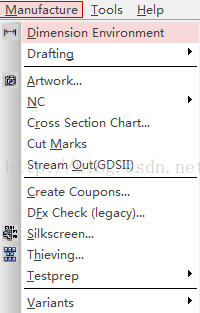
在Manufacture菜单中的Dimension Environment,先左键点击一下,再在软件中点击鼠标右键,会弹出很长的菜单选项,
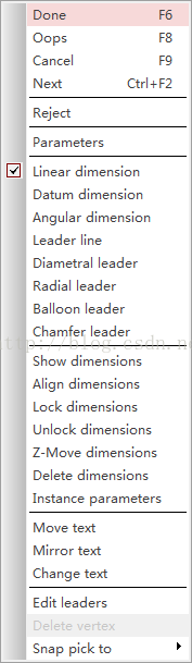
所有有关Dimension尺寸的菜单选项都在这里边,比如参数设置、删除Dimension、标注尺寸等。
菜单介绍:
Parameters——参数,标注尺寸的参数设置,包括格式标准、单位、数字大小等;
Linear dimension——线性尺寸标注;
Datum dimension——相对坐标标注;
Angular dimension——角度标注;
Leader line——带箭头的指引线;
Diametral leader——标注圆形直径;
Radial leader——标注弧形半径;
Balloon leader——圆形标记指引;
Chamfer leader——标注倒角
Show dimension——显示尺寸;
Align dimension——对齐尺寸;
Lock dimension——锁定尺寸;
Unlock dimension——解除锁定尺寸;
Instance parameters——实例参数;
一、参数设置

共5个选项,
1)第一个General选项,一般选默认ANSI或是ISO:
ANSI——American National Standards Institute (default)美国国家标准协会(默认) ;
ISO——International Organization for Standardization国际标准化组织;
BSI ——British Standards Institute英国工业协会;
JIS——Japanese Industrial Standard日本工业标准;
AFNOR——French Association of Normalization法国标准化协会;
DIN——German Industrial Normal德国工业标准;
ANSI
American National Standards Institute (default)
美国国家标准协会
(
默认
)
BSI
British Standards Institute
英国工业协会
DIN
German Industrial Normal
德国工业标准
ISO
International Organization for Standardization
国际标准化组织
JIS
Japanese Industrial Standard
日本工业标准
AFNOR
French Association of Normalization
法国标准化协会
2)第二个Text选项:
主要有上边3个地方需要设置;
1是设置文字大小;
2是设置格式;
Use leading zero before decimal point——在小数点前使用前导零;
Use trailing zero after decimal point——在小数点后使用尾随零;
Align text with demension line——将文本与尺寸对齐;
Use diameter symbol for linear dimension——使用直径尺寸的直径符号;
3是设置单位,主单位和第二单位,一般用mil和mm表示;
3)第三个是Lines的设置:一般默认。
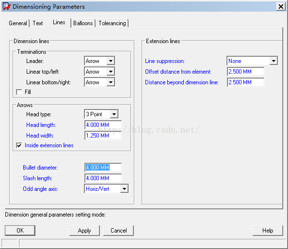
Fill选项和Inside extension lines选项,选与不选的区别,自己试下就可以;

第四个Balloons和第五个Tolerancing就不说了。
二、线性尺寸标注
选中Linear dimension菜单,其中有个Snap pick to选项,打开出现如下界面:

Persistent snap——持续捕捉,默认关闭;
Segment Vertex——段顶点;
Segment Midpoint——段中点;
Segment ——段;
Intersection——交叉;
Shape Center——Shape中心;
Arc/Circle Center——圆弧/圆中心;
Symbol Origin——封装符号原点;
Symbol Center——封装符号中心;
Pad Edge Vertex——焊盘边顶点;
Pad Edge Midpoint——焊盘边中点;
Pad Edge——焊盘边;
Off-gird Location——关闭网格定位;
Gird Point——打开网格定位;
Snap Offset——捕捉偏移量;
一般标注尺寸选对应的捕捉点就可以了。
三、焊盘长宽尺寸标注
如果在PCB中标注焊盘的长宽,选中Persistent snap,再选择Pad Edge三个中的一个,

Find菜单中的选项都关闭,只关闭Symbols和Pins也可以,

鼠标左键点击第一个焊盘的边,软件会自动按你选择的是焊盘边的顶点、焊盘边的中点还是焊盘边来自动定位,然后在点击第二个焊盘的边,就可以了。显示如下:
