在进行数学仿真或者误差评估时,往往认为传感器所引入的噪声服从正态分布(高斯白噪声),这个时候用高斯滤波器就可以很好地消除高斯噪声。高斯滤波也是一种线性平滑滤波,通俗地讲,高斯滤波就是对整幅图像进行加权平均的过程,每一个像素点的值,都由其本身和邻域内的其他像素值经过加权平均后得到。高斯滤波的具体操作:用一个模板(或称卷积、掩模)扫描图像中的每一个像素, 用模板确定的邻域内像素的加权平均灰度值去替代模板中心像素点的值。
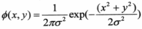
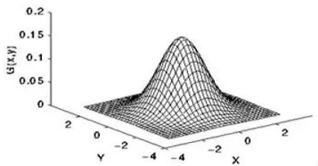
高斯滤波被用作为平滑滤波器的本质原因是因为它是一个低通滤波器,而且大部份基于卷积平滑滤波器都是低通滤波器。高斯模板名字的由来是二维高斯函数,即我们熟悉的二维正态分布密度函数,如下所示:
常用的 3x3 的高斯模板如下所示:

一、MATLAB实现
偷下懒,用函数法实现一下:
clc;
clear all;
close all;

RGB= imread('flower.bmp');              %读取图片
gray = rgb2gray(RGB);                   %灰度图
Gauss_3x3 = fspecial('gaussian',3,2);   %sigma=2的3*3高斯模板
Gauss = imfilter(gray, Gauss_3x3);      %高斯滤波

subplot(2,1,1); imshow(gray);  title('灰度图');
subplot(2,1,2); imshow(Gauss); title('高斯滤波');
点击运行,得到如下结果:
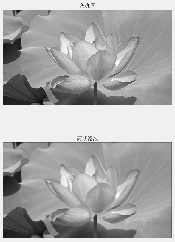
结果和理论一致,图像变得平滑了。
二、FPGA实现
1、形成3x3矩阵
这个在前面的博客花了3篇来解释,就不多说了,我把3x3矩阵的代码用一个专门的 .v 文件写好,这里直接调用即可。输入是灰度数据,即 YCbCr格式中的 8bit Y分量,输出是矩阵数据。耗费 1 个时钟周期。
//==========================================================================
//==    matrix_3x3_8bit,生成3x3矩阵,输入和使能需对齐,耗费1clk
//==========================================================================
//--------------------------------------------------- 矩阵顺序
//        {matrix_11, matrix_12, matrix_13}
//        {matrix_21, matrix_22, matrix_23}
//        {matrix_31, matrix_32, matrix_33}
//--------------------------------------------------- 模块例化
matrix_3x3_8bit
#(
    .COL                    (480                    ),
    .ROW                    (272                    )
)
u_matrix_3x3_8bit
(
    .clk                    (clk                    ),
    .rst_n                  (rst_n                  ),
    .din_vld                (Y_de                   ),
    .din                    (Y_data                 ),
    .matrix_11              (matrix_11              ),
    .matrix_12              (matrix_12              ),
    .matrix_13              (matrix_13              ),
    .matrix_21              (matrix_21              ),
    .matrix_22              (matrix_22              ),
    .matrix_23              (matrix_23              ),
    .matrix_31              (matrix_31              ),
    .matrix_32              (matrix_32              ),
    .matrix_33              (matrix_33              )
);
2、高斯滤波
采用流水线思想,一级一级的往下运算,尽量避免乘除法,共耗费 3 个时钟周期。
//gaussian ------------------------------------------
reg     [11:0]              gs_1                    ;
reg     [11:0]              gs_2                    ;
reg     [11:0]              gs_3                    ;
reg     [11:0]              gs                      ;
//==========================================================================
//==    高斯滤波,耗费3clk
//==========================================================================
//clk1,左中右的一列值
//---------------------------------------------------
always @ (posedge clk or negedge rst_n)begin
    if(!rst_n)begin
        gs_1 <= 'd0;
        gs_2 <= 'd0;
        gs_3 <= 'd0;
    end
    else begin
        gs_1 <= matrix_11      + matrix_12 << 1 + matrix_13;
        gs_2 <= matrix_21 << 1 + matrix_22 << 2 + matrix_23 << 1;
        gs_3 <= matrix_31      + matrix_32 << 1 + matrix_33 ;
    end
end

//clk2,相加
//---------------------------------------------------
always @(posedge clk or negedge rst_n)begin
    if(!rst_n)begin
        gs <= 'd0;
    end
    else begin
        gs <= gs_1 + gs_2 + gs_3;
    end
end

//clk3,除以16 -> 右移4位 -> 取高8位
//---------------------------------------------------
always @(posedge clk or negedge rst_n) begin
    if(!rst_n) begin
        gaussian_data <= 'd0;
    end
    else begin
        gaussian_data <= gs[11:4];
    end
end
3、信号同步
形成矩阵耗费 1clk,高斯滤波耗费 3clk,共 4clk,因此行场和使能信号都需要延迟 4 拍。
//==========================================================================
//==    信号同步
//==========================================================================
always @(posedge clk or negedge rst_n) begin
    if(!rst_n) begin
        Y_de_r    <= 4'b0;
        Y_hsync_r <= 4'b0;
        Y_vsync_r <= 4'b0;
    end
    else begin
        Y_de_r    <= {Y_de_r[2:0],    Y_de};
        Y_hsync_r <= {Y_hsync_r[2:0], Y_hsync};
        Y_vsync_r <= {Y_vsync_r[2:0], Y_vsync};
    end
end

assign gaussian_de    = Y_de_r[3];
assign gaussian_hsync = Y_hsync_r[3];
assign gaussian_vsync = Y_vsync_r[3];
三、上板验证
灰度图:

高斯滤波:
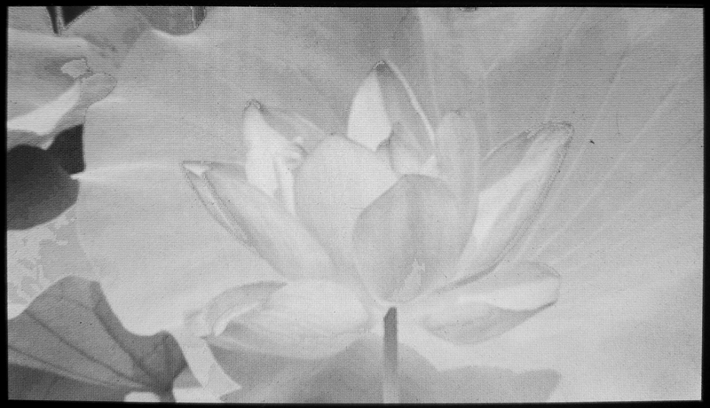
从结果可以看出,图像变得更加平滑,但力度不如上篇的均值滤波,整体细节保留得非常好。
[1] OpenS Lee:FPGA开源工作室(公众号)
[2] CrazyBingo:基于VIP_Board Mini的FPGA视频图像算法(HDL-VIP)开发教程-V1.6
[3] NingHechuan:FPGA图像处理教程