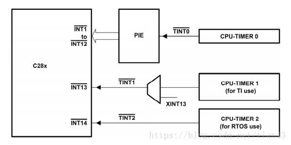
1、DSP28335有3个32位的CPU定时器:定时器 0、1、2。定时器 0、1留给用户使用,输入位系统时钟SYSCLKOUT。
CPU定时器 0 的中断 TINT0 为 PIE 中断,CPU 定时器 1 的中断 TINT1 直接连到 CPU 中断的INT13,CPU 定时器 2 的中断 TINT2 直接连到 CPU 中断的 INT14。
2、定时器核心是一个32位计数器TIMH:TIM 和 一个16位预定标计数器 PSCH:PSC 。它们均进行减计数,且有各自的周期寄存器,分别为 32位周期寄存器 PRDH:PRD 和 16位定时器分频寄存器TDDRH:TDDR 。
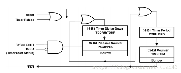
预定标计数器用于将系统时钟SYSCLKOUT分频后作为计数器的计数脉冲,分频系数为TDDRH:TDDR + 1。
计数器根据分频后时钟计数,每计(PRDH:PRO+1)个脉冲中断一次,故定时器中断一次时间为:(PRDH:PRO+1) X (TDDRH:TDDR +1 )X Tsysclkout。
3、寄存器介绍:
TIMERxTIMH 计数器高16位
TIMERxTIM 计数器低16位
TIMERxPRDH 周期寄存器高16位
TIMERxPRO 周期寄存器低16位
TIMERxTPRH 高8位PSCH、低8位TDDRH
TIMERxTPR 高8位PSC、低8位TDDR
这两个寄存器的安排有点皮。。。
TIMERxTCR 定时器控制寄存器(这个寄存器最重要)
位15 TIF 中断标志位 ,1有中断,0无中断
位14 TIE 1允许中断,0禁止中断
位 5 TRB 重载,1装载周期寄存器
位 4 TSS 1停止定时器,0启动定时器
4.CPU定时器中断示例
#include "DSP2833x_Device.h"     // DSP2833x Headerfile Include File
#include "DSP2833x_Examples.h"   // DSP2833x Examples Include File

// Prototype statements for functions found within this file.
interrupt void cpu_timer0_isr(void);
//interrupt void cpu_timer1_isr(void);
//interrupt void cpu_timer2_isr(void);

//#define mem (*(unsigned short int *)0x200000)
#define LED (*(unsigned short int *)0x180000)
#define startCpuTimer0() CpuTimer0Regs.TCR.bit.TSS=0
int i=0,ncount;
unsigned int uLBD;
void main(void)
{

// Step 1. Initialize System Control:
   InitSysCtrl();

// Step 2. Initalize GPIO:
   InitXintf16Gpio();   //zq

// Step 3. Clear all interrupts and initialize PIE vector table:
// Disable CPU interrupts
   DINT;
   InitPieCtrl();
// Disable CPU interrupts and clear all CPU interrupt flags:
   IER = 0x0000;
   IFR = 0x0000;
   InitPieVectTable();

   EALLOW;  // This is needed to write to EALLOW protected registers
   PieVectTable.TINT0 = &cpu_timer0_isr;
   //PieVectTable.XINT13 = &cpu_timer1_isr;
   //PieVectTable.TINT2 = &cpu_timer2_isr;
   EDIS;

// Step 4. Initialize the Device Peripheral. This function can be
   InitCpuTimers();   // For this example, only initialize the Cpu Timers

#if (CPU_FRQ_150MHZ)

   ConfigCpuTimer(&CpuTimer0, 150, 1000000);
   //ConfigCpuTimer(&CpuTimer1, 150, 1000000);
   //ConfigCpuTimer(&CpuTimer2, 150, 1000000);
#endif

#if (CPU_FRQ_100MHZ)


   ConfigCpuTimer(&CpuTimer0, 100, 1000000);
   //ConfigCpuTimer(&CpuTimer1, 100, 1000000);
   //ConfigCpuTimer(&CpuTimer2, 100, 1000000);
#endif

   //CpuTimer0Regs.TCR.all = 0x4001; // Use write-only instruction to set TSS bit = 0
   //CpuTimer1Regs.TCR.all = 0x4001; // Use write-only instruction to set TSS bit = 0
   //CpuTimer2Regs.TCR.all = 0x4001; // Use write-only instruction to set TSS bit = 0

// Step 5. User specific code, enable interrupts:
CpuTimer0Regs.PRD.all=0xffff;
CpuTimer0Regs.TPR.all=0;
CpuTimer0Regs.TIM.all=0;
CpuTimer0Regs.TPRH.all=0;
CpuTimer0Regs.TCR.bit.TSS=1;
CpuTimer0Regs.TCR.bit.SOFT=1;
CpuTimer0Regs.TCR.bit.FREE=1;
CpuTimer0Regs.TCR.bit.TRB=1;
CpuTimer0Regs.TCR.bit.TIE=1;
CpuTimer0.InterruptCount=0;
startCpuTimer0();


   IER |= M_INT1;

   PieCtrlRegs.PIEIER1.bit.INTx7 = 1;


   EINT;   // Enable Global interrupt INTM
   ERTM;   // Enable Global realtime interrupt DBGM


// Step 6. IDLE loop. Just sit and loop forever (optional):
   while(1);


 }


interrupt void cpu_timer0_isr(void)
{
   CpuTimer0.InterruptCount++;

   // Acknowledge this interrupt to receive more interrupts from group 1
   PieCtrlRegs.PIEACK.all = PIEACK_GROUP1;
   CpuTimer0Regs.TCR.bit.TIF=1;
   CpuTimer0Regs.TCR.bit.TRB=1;
   if(ncount==0)
   {  LED=uLBD;
      uLBD++;uLBD%=16;
   }
   ncount++;ncount%=194;
}