If the sketch drawn by UG is exported as a dxf file or Dwg file of AutoCAD, there will be problems such as broken line segments. The online statement of the problem is as follows:

This I also tried to use CGM format conversion but failed
The graphics to be exported as CAD sketches are as follows: First, let's talk about the wrong steps:

Select export in the file option of UG
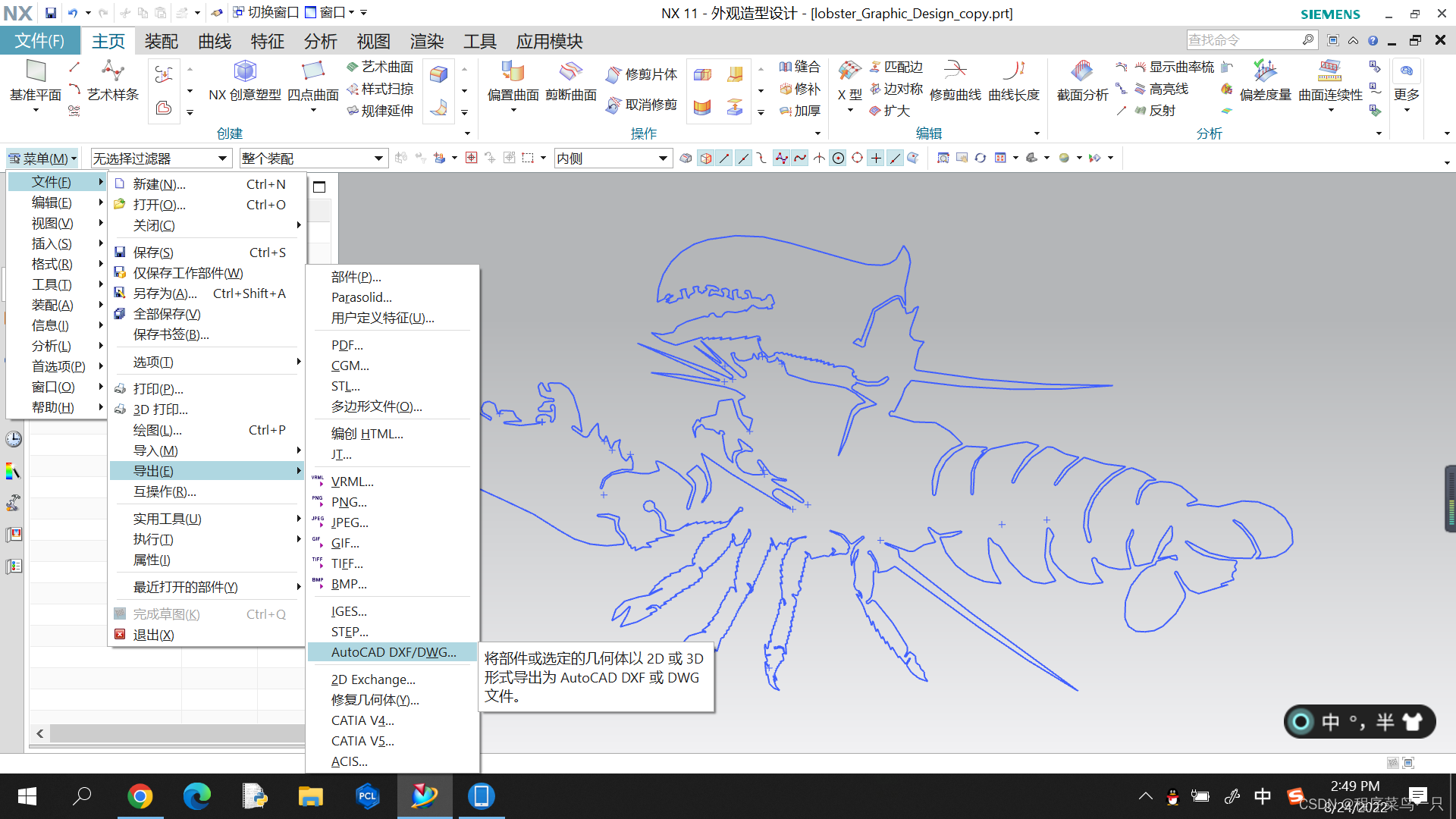
I need to export to CAD2004 format
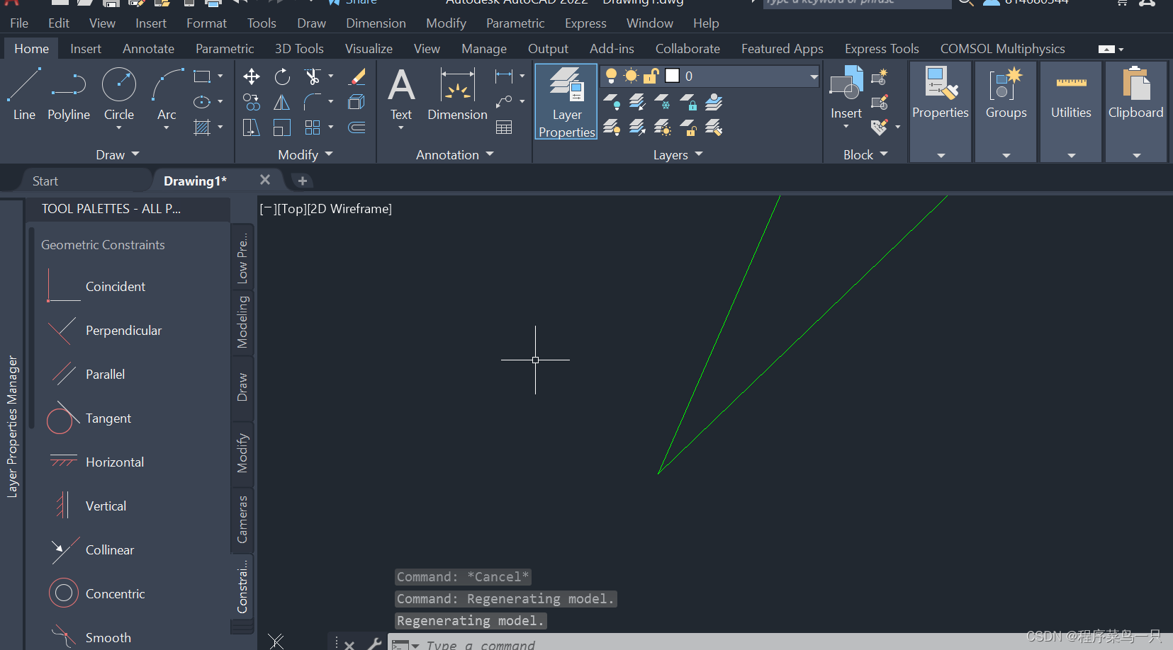
This is the dxf format exported by the above method, but this will cause a disconnection problem. Every time it is selected, only a section of the line will be selected, as shown in Figure 2 below
figure 2
If you magnify the endpoints of the line segments with a high magnification, you will find that the line segments at the endpoints are disconnected and cannot be connected into a whole (the reason is not very clear to me, it may be caused by the difference in writing accuracy when importing CAD and UG)

------------------------------------------------------------------------------------------------------------------------------
So here's the right way to do it:
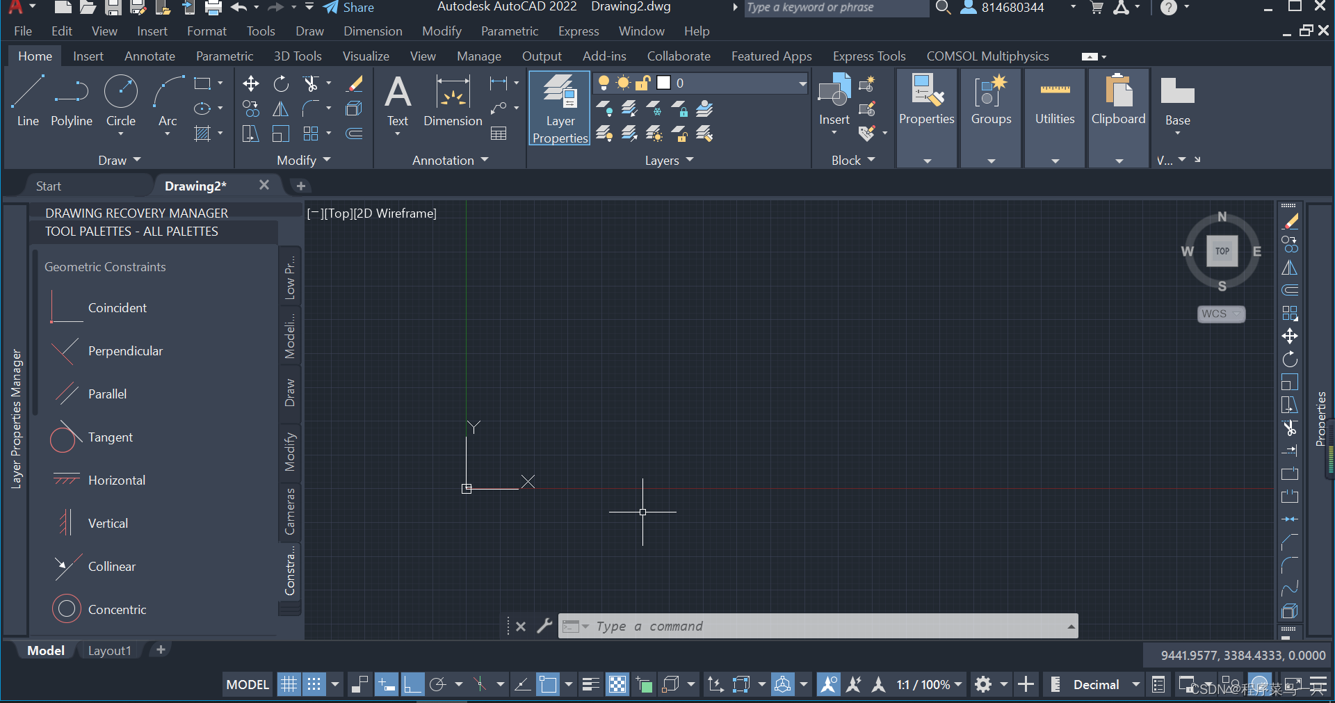
First open the CAD blank interface (my version is CAD2022, it is recommended to use a higher version)
The drawing in NX should only be a sketch, as shown in the figure:

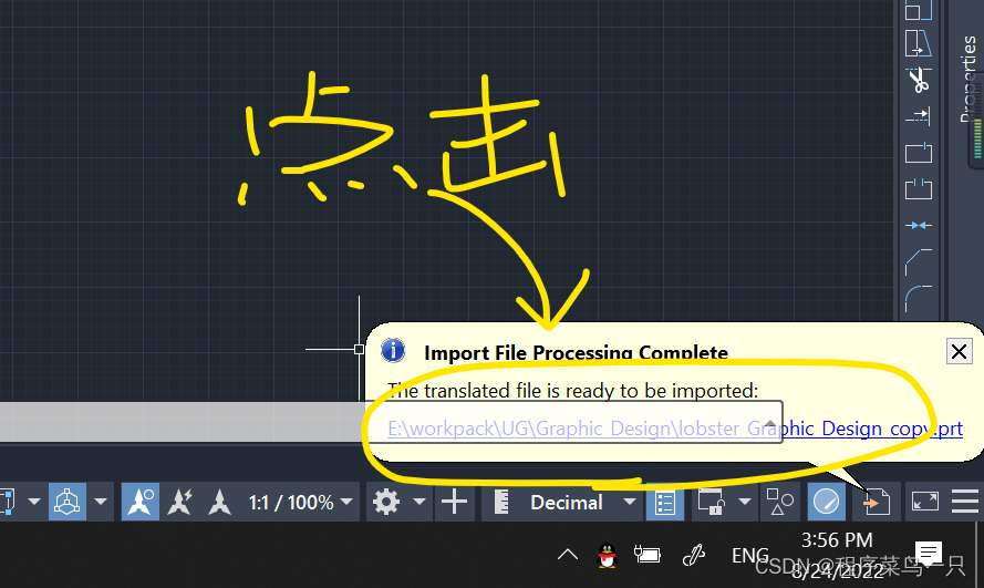
Next, we open an empty CAD dwg or dxf, enter the command IMP and press the space, select the prt file to be imported for direct import
After the bubble box pops up in the lower right corner, click the blue link to import the UG sketch file successfully
If it is not displayed, then press the middle mouse button three times to automatically zoom to the displayed content
So we get the imported file,
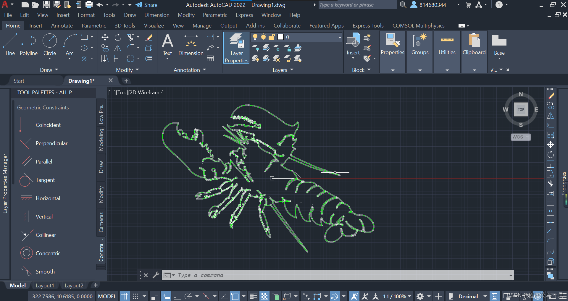
Although this sketch does not look much different from the one above, all the lines can be selected by direct selection, and the entire graph is imported in the form of a whole polyline, even if it is enlarged, the above-mentioned broken line will not appear.

In addition, this method is mainly used for students who draw patterns with UG sketches in metalworking practice wire cutting like me, but the sketches are imported into CAD but the lines are disconnected, and more people refer to them to solve the problem (wire cutting requires a complete polyline)