To draw line segments, cubes, multiple line segments, pipelines:
import vtk.vtkActor;
import vtk.vtkCamera;
import vtk.vtkCellArray;
import vtk.vtkExtractEdges;
import vtk.vtkFloatArray;
import vtk.vtkInteractorStyleTrackballActor;
import vtk.vtkPoints;
import vtk.vtkPolyData;
import vtk.vtkPolyDataMapper;
import vtk.vtkRenderWindow;
import vtk.vtkRenderWindowInteractor;
import vtk.vtkRenderer;
import vtk.* ;
//Then we define our class.
public class Lifangti {
static {
if (!vtkNativeLibrary.LoadAllNativeLibraries()) {
for (vtkNativeLibrary lib : vtkNativeLibrary.values()) {
if (!lib.IsLoaded()) {
System.out.println(lib.GetLibraryName() + " not loaded");
}
}
}
vtkNativeLibrary.DisableOutputWindow(null);
}
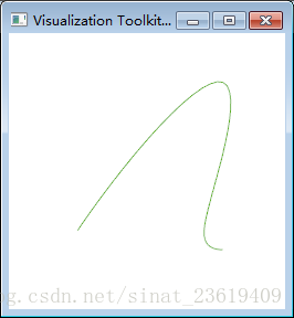
public static void makeYangtiaoquxian(){
vtkPoints points=new vtkPoints();
points.InsertPoint(0, 0.0 ,0.0 ,0.0);
points.InsertPoint(1 ,1.0 ,1.0 ,1.0);
points.InsertPoint(2 ,1.0, 0.0 ,0.0);
points.InsertPoint(3, 1.0 ,0.0, 1.0);
//Interpolate to spline curve
vtkParametricSpline spline =new vtkParametricSpline();
spline.SetPoints(points);
spline.ClosedOff();
vtkParametricFunctionSource splineSource =new vtkParametricFunctionSource();
splineSource.SetParametricFunction(spline);
vtkPolyDataMapper splineMapper =new vtkPolyDataMapper();
splineMapper.SetInputConnection(splineSource.GetOutputPort());
vtkActor splineActor =new vtkActor();
splineActor.SetMapper(splineMapper);
splineActor.GetProperty().SetColor(0.3800 ,0.7000 ,0.1600);
vtkTubeFilter tube= new vtkTubeFilter();
tube.SetInputData(splineSource.GetOutput());
tube.SetNumberOfSides (20);
tube.SetRadius(50);
vtkPolyDataMapper tubeMapper=new vtkPolyDataMapper();
tubeMapper.SetInputData(tube.GetOutput());
vtkActor tubeActor=new vtkActor();
tubeActor.SetMapper(tubeMapper);
vtkRenderer ren1=new vtkRenderer();
vtkRenderWindow renWin=new vtkRenderWindow();
renWin.AddRenderer (ren1);
vtkRenderWindowInteractor iren=new vtkRenderWindowInteractor();
iren.SetRenderWindow (renWin);
ren1.AddActor(splineActor);
ren1.AddActor(tubeActor);
ren1.SetBackground(1, 1, 1);
renWin.SetSize(250 ,250);
renWin.Render();
iren.Start();
}
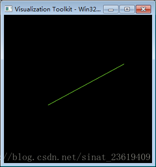
public static void makeYuanzhuti(){
double[][] x={{10,10,0},{20.33,20,0},{20.3,10.3,0},{10,20.3,0},
{10,10,20.3},{10.3,10,20.3},{30.3,40.3,20.3},{10,20.3,20.3}};
vtkLineSource line =new vtkLineSource();
line.SetPoint1(x[0]);
line.SetPoint2(x[1]);
vtkPolyDataMapper splineMapper =new vtkPolyDataMapper();
splineMapper.SetInputConnection(line.GetOutputPort());
vtkActor splineActor =new vtkActor();
splineActor.SetMapper(splineMapper);
splineActor.GetProperty().SetColor(0.3800 ,0.7000 ,0.1600);
vtkTubeFilter tubeFilter = new vtkTubeFilter();
tubeFilter.SetInputConnection(line.GetOutputPort());
tubeFilter.SetRadius(9.0);
tubeFilter.SetNumberOfSides (100);
tubeFilter.CappingOn();
vtkPolyData cube =new vtkPolyData();
//This is used to save what we call the topology between the points, because according to the VTK process, we have to do this and pack it step by step.
vtkCellArray polys =new vtkCellArray();
//This is about the attribute value of the color, so I won't focus on it here.
vtkFloatArray scalars =new vtkFloatArray();
//It's still the same reason, because we use the points defined by ourselves, not the vtksphere, vtkcone and other sources in VTK, so we must put the points in vtkPoints
vtkPoints points =new vtkPoints();
//Put our defined points into points, where i is the real index, if our loop starts from i=8
//The index of the real point, and the reference in the cell, will be consistent with this index
for (int i=0;i<8;i++) points.InsertPoint(i, x[i]);
cube.SetPoints(points);
cube.SetPolys(polys);
vtkPolyDataMapper cubeMapper =new vtkPolyDataMapper();
cubeMapper.SetInputData(tubeFilter.GetOutput());
vtkActor tempactor = new vtkActor ();
tempactor.SetMapper (cubeMapper);
vtkRenderer renderer =new vtkRenderer();
renderer.AddActor (tempactor);
renderer.AddActor(splineActor);
vtkCamera camera =new vtkCamera();
camera.SetPosition(1,1,1);
camera.SetFocalPoint(0,0,0);
vtkRenderWindow reWin = new vtkRenderWindow();
reWin.AddRenderer(renderer);
vtkRenderWindowInteractor iren =new vtkRenderWindowInteractor();
iren.SetRenderWindow (reWin);
//If this style is removed, the entire cube will rotate together when interacting
//If added, each cube rotates independently
// vtkInteractorStyleTrackballActor style =new vtkInteractorStyleTrackballActor();
// iren.SetInteractorStyle(style);
renderer.SetActiveCamera(camera);
renderer.ResetCamera();
renderer.SetBackground(0,0,0);
reWin.SetSize(300,300);
reWin.Render();
iren.Initialize();
iren.Start();
}
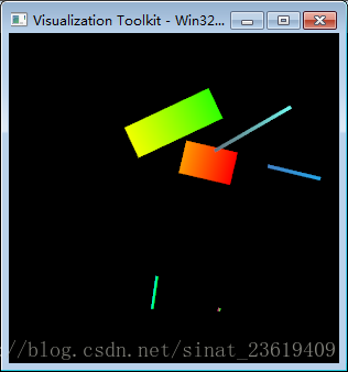
public static void makeManyLines(){
double[][] x={{10,10,0},{15.33,10,0},{20.3,10.3,0},{10,20.3,0},
{10,10,20.3},{10.3,10,20.3},{30.3,40.3,20.3},{10,20.3,20.3}};
int numb=5;
//concrete dataset represents vertices, lines, polygons, and triangle strips, this is the description in the document, it is more clear.
vtkPolyData polyData =new vtkPolyData();
//This is used to save what we call the topology between the points, because according to the VTK process, we have to do this and pack it step by step.
//This is about the attribute value of the color, so I won't focus on it here.
vtkFloatArray scalars =new vtkFloatArray();
//It's still the same reason, because we use the points defined by ourselves, not the vtksphere, vtkcone and other sources in VTK, so we must put the points in vtkPoints
vtkPoints points =new vtkPoints();
vtkLine line2 = new vtkLine();
vtkCellArray lines2 = new vtkCellArray();
//This CellArray is more important, it can't run without this
for(int ID2=0;ID2<numb;ID2=ID2+2)
{
line2.GetPointIds().SetId(0,ID2);
line2.GetPointIds().SetId(1,ID2+1);
lines2.InsertNextCell(line2);
}
//After this loop ends, all the required line segments in points_2clip will be drawn. If it is a polyline segment determined by three points, // is the following code
vtkPolyLine line3 =new vtkPolyLine();
vtkCellArray lines3 = new vtkCellArray();
for(int ID3=0;ID3<numb;ID3=ID3+3)
{
line3.GetPointIds (). SetNumberOfIds (3);
line3.GetPointIds().SetId(0,ID3);
line3.GetPointIds().SetId(1,ID3+1);
line3.GetPointIds().SetId(2,ID3+2);
lines3.InsertNextCell(line3);
}
/* Next is vtkPolyData.vtkPolyDataMapper.vtkActor.vtkRenderer.vtkRenderWindow.vtkRenderWindowInteractor,
In order to better show the relationship between points and lines, I also used vtkVertexGlyphFilter,
It is used to display all the points used, and vtkAxesActor is also added to display the coordinate axis, which is relatively more intuitive. */
for (int i=0;i<x.length;i++) points.InsertPoint(i, x[i]);
for (int i=0;i<x.length;i++) scalars.InsertTuple1(i,i);
//Then the pipeline process of VTK starts.
polyData.SetPoints(points);
polyData.SetLines(lines2); //lines3
polyData.GetPointData().SetScalars(scalars);
vtkPolyDataMapper cubeMapper =new vtkPolyDataMapper();
cubeMapper.SetInputData(polyData);
cubeMapper.SetScalarRange(0,7);
vtkActor tempactor = new vtkActor ();
tempactor.SetMapper (cubeMapper);
tempactor.GetProperty (). SetColor (1, 1, 1);
tempactor.SetPosition (5,5,5);
tempactor.GetProperty (). SetLineWidth (30);
vtkPolyDataMapper polyDataMapper =new vtkPolyDataMapper();
vtkLookupTable lut= new vtkLookupTable();
lut.SetNumberOfTableValues (10);
for(int i=0;i<10;++i)
lut.SetTableValue(i, Math.random(), Math.random(), Math.random(),1);
polyDataMapper.SetInputData(polyData);
polyDataMapper.SetLookupTable (lut);
polyDataMapper.SetScalarRange(0,10);
polyDataMapper.SetScalarModeToDefault();
vtkActor actor =new vtkActor ();
actor.SetMapper(polyDataMapper);
actor.PickableOff();
actor.GetProperty().SetLineWidth(3);
vtkRenderer renderer =new vtkRenderer();
renderer.AddActor (tempactor);
renderer.AddActor(actor);
vtkCamera camera =new vtkCamera();
camera.SetPosition(1,1,1);
camera.SetFocalPoint(0,0,0);
vtkRenderWindow reWin = new vtkRenderWindow();
reWin.AddRenderer(renderer);
vtkRenderWindowInteractor iren =new vtkRenderWindowInteractor();
iren.SetRenderWindow (reWin);
//If this style is removed, the entire cube will rotate together when interacting
//If added, each cube rotates independently
// vtkInteractorStyleTrackballActor style =new vtkInteractorStyleTrackballActor();
// iren.SetInteractorStyle(style);
renderer.SetActiveCamera(camera);
renderer.ResetCamera();
renderer.SetBackground(0,0,0);
reWin.SetSize(300,300);
reWin.Render();
iren.Initialize();
iren.Start();
}
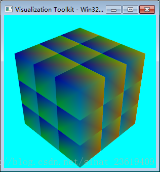
public static void makeLifangti(){
int i ;
//You can see that there are 27 small cubes in the figure to form a large cube
//x[8][3], is the x, y, z value of the 8 points of each small cube
//java float type needs to be followed by f to represent float type data
//float[][] x= {{0,0,0},{0.3f,0,0},{0.3f,0.3f,0},{0,0.3f,0}, {0,0,0.3f},{0.3f,0,0.3f},{0.3f,0.3f,0.3f},{0,0.3f,0.3f}};
double[][] x={{0,0,0},{0.3,0,0},{0.3,0.3,0},{0,0.3,0},
{0,0,0.3},{0.3,0,0.3},{0.3,0.3,0.3},{0,0.3,0.3}};
//This review of the VTK documentation found that the explanation was different from what I understood. . . Most likely I don't understand it. . .
//My understanding is this, a cube is composed of 6 faces, and our program is also planning to use the cell with the smallest face position to form the cube we want
//Of course, we can also use lines to draw, so we can only draw the border of the cube, we can't use the PolyData used below, but use the vtkLine object as the CELL
//Since it is selected to be composed of faces, six faces are generated. The first face is composed of four points 0, 1, 2, and 3 of the 8 points defined above, and so on.
//Specially note that the points 0, 1, 2, and 3 here are not the corresponding x[8][3]. The specific reasons for the 0, 1, 2, and 3 here will be explained below.
//Each number represents the index subscript of the point data
int [] [] pts = {{0,1,2,3}, {4,5,6,7}, {0,1,5,4}, {1,2,6,5}, {2 , 3,7,6}, {3,0,4,7}};
//concrete dataset represents vertices, lines, polygons, and triangle strips, this is the description in the document, it is more clear.
vtkPolyData cube =new vtkPolyData();
//This is used to save what we call the topology between the points, because according to the VTK process, we have to do this and pack it step by step.
vtkCellArray polys =new vtkCellArray();
//This is about the attribute value of the color, so I won't focus on it here.
vtkFloatArray scalars =new vtkFloatArray();
//It's still the same reason, because we use the points defined by ourselves, not the vtksphere, vtkcone and other sources in VTK, so we must put the points in vtkPoints
vtkPoints points =new vtkPoints();
//Put our defined points into points, where i is the real index, if our loop starts from i=8
//The index of the real point, and the reference in the cell, will be consistent with this index
for (i=0;i<8;i++) points.InsertPoint(i, x[i]);
// Topology of the insertion point,
//November 10, 2011 - god_sun - Sui Feng¤ Xinhui
//Although the first parameter is of type vtkIdType, it is actually of type int. The explanation in the document is that the first parameter is the number of points, and the second is the content of the point.
//The setting unit consists of several points, and each unit specifies the corresponding point
for (i=0;i<6;i++)
{
polys.InsertNextCell(4);
for(int j=0;j<4;j++){
polys.InsertCellPoint(pts[i][j]);
}
}
for (i=0;i<8;i++) scalars.InsertTuple1(i,i);
//Then the pipeline process of VTK starts.
cube.SetPoints(points);
cube.SetPolys(polys);
cube.GetPointData().SetScalars(scalars);
//// This code is to show the border around the cube. . . But setting visibilityOn or visibilityOff doesn't seem very obvious.
//When I used to draw a cube in photoshop, I would draw a border around it, which would make it feel fuller. . .
//Use SetInputData(cube) after vtk5; the previous format is SetInput(cube)
vtkExtractEdges extract=new vtkExtractEdges();
extract.SetInputData(cube);
vtkPolyDataMapper mapEdges=new vtkPolyDataMapper();
mapEdges.SetInputConnection(extract.GetOutputPort());
mapEdges.SetScalarVisibility(0);
vtkActor edgeActor=new vtkActor();
edgeActor.SetMapper(mapEdges);
edgeActor.VisibilityOn();
vtkPolyDataMapper cubeMapper =new vtkPolyDataMapper();
cubeMapper.SetInputData(cube);
cubeMapper.SetScalarRange(0,7);
int No=0;
//p,j,k are to set the different positions of the cube.
float p=0.0f,j=0.0f,k=0.0f;
vtkRenderer renderer =new vtkRenderer();
for (p=0.0f;p<0.9;p=p+0.3f)
{
for (j=0.0f;j<0.9;j=j+0.3f)
{
for(k=0.0f;k<0.9;k=k+0.3f)
{
vtkActor cubeActor =new vtkActor();
//Set different positions of ACTOR to display the final graph.
cubeActor.SetPosition(p,j,k);
cubeActor.SetMapper(cubeMapper);
renderer.AddActor(cubeActor);
}
}
}
vtkCamera camera =new vtkCamera();
camera.SetPosition(1,1,1);
camera.SetFocalPoint(0,0,0);
vtkRenderWindow reWin = new vtkRenderWindow();
reWin.AddRenderer(renderer);
vtkRenderWindowInteractor iren =new vtkRenderWindowInteractor();
iren.SetRenderWindow (reWin);
//If this style is removed, the entire cube will rotate together when interacting
//If added, each cube rotates independently
vtkInteractorStyleTrackballActor style =new vtkInteractorStyleTrackballActor();
iren.SetInteractorStyle(style);
renderer.SetActiveCamera(camera);
renderer.ResetCamera();
renderer.SetBackground(0,1,1);
reWin.SetSize(300,300);
reWin.Render();
iren.Initialize();
iren.Start();
}
public static void main(String[] args) {
// TODO Auto-generated method stub
makeYangtiaoquxian();
makeYuanzhuti();
makeManyLines ();
makeLifangti();
}
}
Result graph: