Review of Visual SLAM Methods for Autonomous Vehicles
The original paper is at the end of the article.
Summary:
Autonomous vehicles require precise localization and mapping solutions in different driving environments. In this case, simultaneous localization and mapping (SLAM) technology is a good research solution. Light detection and ranging (LIDAR) and camera sensors are commonly used for localization and perception. However, through a decade or two of evolution, LiDAR-SLAM methods seem to have changed little. Compared with lidar-based schemes, visual SLAM has strong scene recognition capabilities, and has the advantages of low cost and easy installation. In fact, in the field of autonomous driving, people are trying to replace lidar sensors with cameras, or integrate other sensors on the basis of cameras. Based on the current state of research on visual SLAM, this review covers visual SLAM techniques. In particular, we first illustrate the typical structure of visual SLAM. Second, a comprehensive review of the state-of-the-art research on vision and vision-based (i.e., vision-inertial, vision-lidar, vision-lidar-IMU) SLAM and compares our previous work with well-known frameworks on public datasets The positioning accuracy was compared. Finally, the key issues and future development trends of visual SLAM technology in autonomous vehicle applications are discussed.
Questions and solutions:
Unlike indoor or outdoor mobile robots tested by most developed visual SLAM methods, autonomous vehicles have more complex parameters to consider, especially when the vehicle drives autonomously in an urban environment. For example, the scale of the environment region is large and has dynamic obstacles, making the performance of visual SLAM methods less accurate and robust (Cadena et al., 2016a). Issues such as error accumulation, lighting changes, and fast motion lead to estimation problems. To address these issues associated with autonomous vehicles, various approaches have been considered. Such as visual odometry (VO) algorithm based on feature point/direct/semi-direct/point-line fusion. and Extended Kalman Filter (EKF)/graph-based optimization algorithms for pose estimation (Takleh et al., 2018). In addition, vision-based multi-sensor fusion methods have also attracted great attention in improving the accuracy of autonomous systems.
Article Arrangement:
As far as the vision-based SLAM system is concerned, in addition to the mapping module, the collection of sensor data, such as cameras or inertial measurement units (IMUs), VO and visual-inertial odometry (VIO) systems are all completed in the front end, while optimization and closed-loop are in the back end. end complete. Relocalization is always considered as an additional module to improve the accuracy of visual SLAM systems (Taketomi et al., 2017). In this paper, visual SLAM methods are reviewed. Mainly considering the positioning accuracy of the visual SLAM system, the methods that may be applied to autonomous driving scenarios are studied in as much detail as possible, including pure visual SLAM methods, visual-inertial SLAM methods and visual-lidar-inertial SLAM methods, and our Previous work compares the localization accuracy of well-known methods on public datasets. This review provides a detailed survey of visual SLAM techniques and can serve as a friendly guide for new researchers in the field of autonomous vehicles. At the same time, it can also be considered as a dictionary of possible directions for experienced researchers looking for future work. The rest of this paper is structured as follows. First, we introduce the principles of the visual SLAM system, and in Section II we review the responsibilities of the camera sensor, front-end, back-end, loop closure and mapping modules. Second, state-of-the-art research on vision, vision-inertial, vision-lidar, and vision-lidar-IMU SLAM methods is illustrated in Section 3. Section III discusses the key issues and future development trends of visual SLAM technology in autonomous vehicle applications. Finally, conclusions are drawn in Section 5.
Principles of Visual SLAM

Principles of Visual SLAM The classic structure of a visual SLAM system can be divided into five parts. Camera sensor module, front-end module, back-end module, closed-loop module and mapping module. As shown in Figure 1, the camera sensor module is responsible for collecting image data, the front-end module is responsible for tracking the image features between two adjacent frames, and realizes the initial camera motion estimation and local mapping, and the back-end module is responsible for numerical optimization from the front-end and further For motion estimation, the loop-closing module is responsible for eliminating cumulative errors by calculating image similarity in large-scale environments, and the mapping module is responsible for reconstructing the surrounding environment (Gao et al., 2017).
“2.1. Camera sensors”
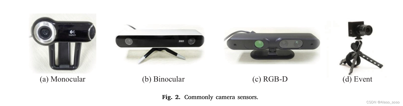
According to different types of sensors, common vision sensors can be mainly divided into monocular, binocular, RGB-D and event cameras. The sensor of the camera is shown in Figure 2. (a). Monocular camera, monocular camera has the advantages of low cost and simple layout. However, the depth of landmarks cannot be well estimated, which has a problem of scale ambiguity during map construction (Haomin et al., 2016). Also, pixel distances cannot be obtained when the camera is stationary (no translation) or only purely rotated. (b). Compared with monocular cameras, binocular SLAM can rely on camera measurements to calculate pixel depth in a static state. It has also been proven to be more robust than monocular SLAM in outdoor environments. However, the range of depth measurement is limited by the baseline length and resolution, and the process of parameter configuration and calibration is also complicated because the camera needs to process double image information, which is more computationally expensive for the central processing unit (CPU). (c). RGB-D cameras, unlike monocular and binocular cameras, RGB-D cameras can directly obtain pixel depth through infrared structured light and/or time-of-flight (TOF), avoiding complex calculations. The theory of TOF is to calculate the distance by measuring the flight time of the laser. However, RGB-D cameras are considered unsuitable for outdoor applications, such as autonomous driving scenarios, due to their narrow measurement range and high susceptibility to sunlight interference. (d). Event camera, the event camera has a high dynamic range of 140dB, while other cameras cannot reach 60dB, in addition, it has high temporal resolution, low power consumption, and is not affected by motion blur. The literature (Gallego et al., 2019) states that instead of capturing images at a fixed rate, event cameras measure per-pixel brightness changes in an asynchronous manner. Therefore, event cameras perform better in odometry under high-speed and high-dynamic conditions. Event cameras can be classified into dynamic vision sensors (Lichtsteiner et al., 2008; Son et al., 2017a; Posch et al., 2009; Hofstatter et al., 2010), dynamic line sensors (Posch et al., 2007), dynamic and active pixel vision sensors (Brandli et al., 2014) and time-based asynchronous image sensors (Posch et al., 2010).
The popular Vision Sensor manufacturers and products in the market are listed below, but not limited thereto.
• MYNTAI: S1030 Series (stereo camera with IMU), D1000 Series (depth camera), D1200 Series (apply to smart phones).
• Stereolabs ZED: Stereolabs ZED camera (Depth Range: 1.5 to 20 m).
• Intel: 200 Series, 300 Series, Module D400 Series, D415 (Active IR Stereo, Rolling shutter), D435 (Active IR Stereo, Global Shutter), D435i (Integrated IMU).
• Microsoft: Azure Kinect (Apply to microphone with IMU), Kinectc-v1(structured-light), Kinect-v2 (TOF).
• Occipital Structure: Structure Camera (apply to ipad).
• Samsung: Gen2 and Gen3 dynamic cameras and event-based visual solution (Son et al., 2017b).”
“2.2. Front end”
The front end of visual SLAM is called visual odometry (VO). It is responsible for roughly estimating camera motion and feature orientation based on information from neighboring frames. In order to obtain accurate attitude with fast response speed, an efficient VO is necessary. Currently, front-ends can be mainly divided into two categories: feature-based methods and direct methods (including semi-direct methods) (Zou et al., 2020). In this section, we mainly review feature-based VO methods. Regarding semi-direct and direct methods, such as SVO (Forster et al., 2017) and DSO (Engel et al., 2018) are described in Section 3.1.2. The VO system based on feature points is more stable and relatively insensitive to light and dynamic objects. Feature extraction methods with high scale and good rotation invariance can greatly improve the reliability and stability of VO systems (Chen et al., 2019).
In 1999, Lowe (2004) proposed the Scale Invariant Feature Transform (SIFT) algorithm, which was improved and developed in 2004. The overall algorithm is divided into three steps to complete the extraction and description of image feature points.
(i). The scale space is constructed by the Gaussian difference pyramid method, and the interest points are identified by the Gaussian difference function.
(ii). Determine the location and scale of each candidate point, and then locate these key points.
(iii). Assign directional features to key points to obtain descriptors.
SIFT features perform non-deformation on rotation, scaling, and illumination changes, but it consumes a lot of computation. Speeded Up Robust Features (SURF) (Herbert et al., 2007) is an improvement of SIFT. It solves the shortcomings of SIFT's large amount of calculation and poor real-time performance, and also maintains the excellent performance of the SIFT operator. Nevertheless, the SURF algorithm has great limitations when applied to real-time SLAM systems. On the basis of ensuring performance, a feature extraction algorithm that pays more attention to computing speed is proposed. In 2011, Viswanathan (2011) proposed a local corner detection method based on templates and machine learning methods, that is, the feature from accelerated segment test (FAST) corner detection method. The FAST algorithm takes the pixel to be detected as the center of the circle, and when the gray difference between other pixels on the circle with a fixed radius and the pixel at the center of the circle is large enough, the point is considered a corner. However, FAST corners have no orientation and scale information, and they are not rotation and scale invariant. In 2012, Rublee et al. (2012) proposed the Oriented FAST and Rotated BRIEF (ORB) algorithm based on FAST corners and BRIEF descriptors. The algorithm first builds an image pyramid on the image, then detects FAST key points and calculates the feature vector of the key points. The descriptor of ORB adopts the fast calculation speed of the binary string feature BRIEF descriptor (Michael et al., 2010), so the calculation speed of ORB is faster than the real-time feature detection speed of the FAST algorithm. In addition, ORB is less affected by noise, has good rotation invariance and scale invariance, and can be applied to real-time SLAM systems. In 2016, Chien et al. (2016) compared and evaluated SIFT, SURF, and ORB feature extraction algorithms in VO applications. Through extensive testing on the KITTI dataset (Geiger et al., 2013), it can be concluded that SIFT has the highest accuracy in extracting features, while ORB has less computation. Therefore, as an embedded computer with limited computing power, the ORB method is considered more suitable for the application of autonomous vehicles.
“2.3. Back end”
The backend receives the camera pose estimated by the frontend and optimizes the initial pose to obtain a globally consistent motion trajectory and environment map (Sunderhauf and Protzel, 2012). Compared with the diversified front-end algorithms, the current types of back-end algorithms can be mainly divided into two categories. Filter-based methods (such as Extended Kalman Filter (EKF) Bailey et al., 2006), and optimization-based methods (such as factor graph Wrobel, 2001). They are described below.
(a). Based on the filter method, this method mainly uses the Bayesian principle to estimate the current state based on the previous state and the current observation data (Liu, 2019). Typical filter-based methods include Extended Kalman Filter (EKF) (Bailey et al., 2006), Unscented Kalman Filter (UKF) (Wan and Merwe, 2000) and Particle Filter (PF) (Arnaud et al., 2000) . Taking the typical EKF-based SLAM method as an example, its application in small-scale environments is relatively successful. However, since the covariance matrix is stored, its storage capacity increases with the square of the state quantity, and its application to large unknown scenarios is always limited.
(b). Based on the optimization method, the core idea based on the nonlinear optimization (graph optimization) method is to convert the back-end optimization algorithm into the form of a graph, with the object pose and the environmental characteristics at different moments as the vertices, and the distance between vertices Constraint relations of L are represented by edges (Liang et al., 2013). After the graph is built, optimization-based algorithms are used to solve the pose of the subject so that the state to be optimized on the vertices better satisfies the constraints on the corresponding edges. After the optimization algorithm is executed, the corresponding graph is the motion trajectory of the subject and the environment graph. Currently, most mainstream visual SLAM systems use nonlinear optimization methods.
“2.4. Loop closing”
The task of the closed loop is to allow the system to identify the current scene based on the sensor information, and determine that the area has been visited when returning to the original place, that is, to eliminate the cumulative error of the SLAM system (Newman and Ho, 2005). For visual SLAM, the traditional closed-loop detection method mainly uses the Bag-of-Words (BoW) model (Galvez-LoPez and Tardos, 2012), and the implementation steps are:
(i). For the local features extracted from the image, construct a vocabulary containing K words through K-means clustering.
(ii). Represent the image as a K-dimensional numeric vector according to the number of occurrences of each word.
(iii). Judging the difference of the scene and identifying whether the self-driving car has reached the recognized scene.
“2.5. Mapping”
A fundamental component of an autonomous vehicle is the ability to build a map of its environment and orient itself on the map. Mapping is one of the two tasks of a visual SLAM system (i.e., localization and mapping), which plays an important role in navigation, obstacle avoidance, and environment reconstruction for autonomous driving. In general, map representations can be divided into two categories: metric maps and topological maps. Metric maps describe the relative positional relationship between map elements, while topological maps emphasize the connection relationship between map elements. For classic SLAM systems, metric maps can be further divided into sparse maps and dense maps. Sparse maps contain only a small amount of information in the scene and are suitable for positioning, while dense maps contain more information, which is beneficial for vehicles to perform navigation tasks based on the map.
“3. State-of-the-art studies”
“3.1. Visual SLAM
Similar to the VO subsystem described in Section 2.2, pure visual SLAM systems can be divided into two categories according to the method of exploiting image information: feature-based methods and direct methods. Feature-based methods refer to estimating camera motion between adjacent frames and constructing an environment map by extracting and matching feature points. The disadvantage of this method is that it takes a long time to extract feature points and calculate descriptors. Therefore, some researchers propose to abandon the computation of keypoints and descriptors, and direct methods emerge (Zou et al., 2020). Furthermore, according to the type of sensor, visual SLAM can be classified into monocular, binocular, RGB-D, and event camera-based methods. According to the density of the map, it can be divided into sparse, dense and semi-dense SLAM, which are introduced as follows.
"3.1.1. Feature-based method" is based on features
In 2007, Davison et al. (2007) proposed the first real-time monocular vision SLAM system, Mono-SLAM. The results of real-time feature module orientation estimation are shown in Fig. 3(a). The EKF algorithm is used in the backend to track the sparse feature points obtained from the frontend, and the camera pose and landmark orientation are used as state variables to update their mean and covariance. In the same year, Klein and Murray (2007) proposed a parallel tracking and mapping system, PTAM. It parallelizes tracking and mapping work. Figure 3(b) shows the process of feature extraction and mapping, which distinguishes the front-end and back-end for the first time, and proposes a key-frame mechanism through a nonlinear optimization method. Key images are concatenated to optimize motion trajectories and feature orientations. Many subsequent designs of visual SLAM systems have followed a similar approach. In 2015, Mur-Artal et al. (2015) proposed ORB-SLAM, which is a relatively complete keyframe-based monocular SLAM method. Compared with the dual-thread mechanism of PTAM, this method divides the whole system into three threads: tracking, mapping and loop closure detection. It should be noted that the process of feature extraction and matching (left column), map construction and cycle detection are all based on ORB features (right column). Figure 3(c) is the real-time feature extraction process (left column) and trajectory tracking and mapping results (right column) of the monocular camera in the college road environment. In 2017, Mur-Artal et al. proposed a follow-up version of ORB-SLAM2 (Murartal and Tardos, 2017), which supports loop detection and relocation, and has the function of real-time map reuse. In addition, the improved framework also opens up binocular cameras. Interface with RGB-D camera. The left column of Fig. 3(d) shows the binocular trajectory estimation and feature extraction of ORB-SLAM2. The right column of Fig. 3(d) shows the keyframe and dense point cloud mapping effects of RGB-D cameras in indoor scenes. The continuous small green squares in the figure constitute the trajectory of the keyframe, and the dense 3D scene map built by the RGB-D camera surrounds it.
"3.1.2. Direct based method" direct method
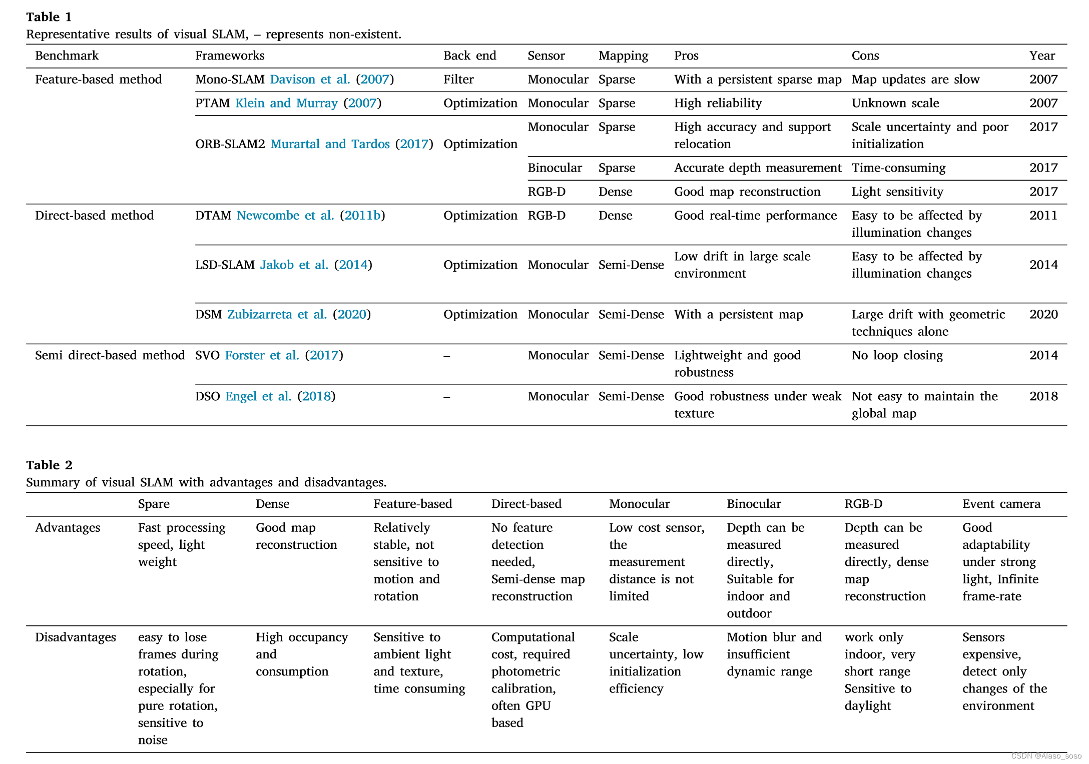
In 2011, Newcombe et al. (2011b) proposed a monocular SLAM framework based on direct methods, namely DTAM. Different from feature-based methods, DTAM employs an inverse depth-based method to estimate the depth of features. The camera pose is computed by direct image matching, and a dense map is constructed by an optimization-based approach (Fig. 4(a)). In 2014, Jakob et al. (2014) proposed LSD-SLAM (Fig. 4(b)), which is a successful application of the direct method in the monocular vision SLAM framework. This method applies a pixel-oriented approach to a semi-dense monocular SLAM system. Compared with feature-based methods, LSD-SLAM is less sensitive, but the system is vulnerable when the intrinsic parameters of the camera and illumination changes. In 2017, Forster et al. (2017) proposed SVO (Semi-direct Visual Odometry). It uses sparse direct methods (also known as semi-direct methods) to track keypoints (bottom of Figure 4(c)) and estimate poses based on information around the keypoints. The top of Figure 4(c) shows the traces of the sparse map in an indoor environment. Due to the semi-direct approach to track sparse features, neither computing descriptors nor processing dense information, SVO has low time complexity and strong real-time performance. In 2016, Engel et al. (2018) proposed DSO, which also uses a semi-direct method to guarantee higher accuracy at a faster operating speed. However, as in Section 2. As mentioned in Section 1, they are only visual odometry. Due to the lack of back-end optimization modules and closed-loop modules, the tracking error of the system will accumulate over time. Figure 4(d) shows the effect of DSO (monocular odometry) for 3D reconstruction and tracking. The direct method has the advantages of fast calculation speed and insensitivity to weak characteristic conditions. However, it is based on the strong assumption of constant gray levels, so it is very sensitive to changes in illuminance. In contrast, feature point methods have good invariance characteristics. In 2020, Zubizarreta et al. (2020) proposed a direct sparse mapping method, or DSM, which is a full monocular vision SLAM system based on the photometric beam adjustment (PBA) algorithm. A qualitative example tested on the EuRoC dataset (V1_03_hard sequences) is shown in Fig. 4(e). It has been shown to reduce both estimated trajectory and map errors while avoiding inconsistent map point duplication. Table 1 summarizes the main features and strengths and weaknesses of state-of-the-art visual SLAM frameworks. In addition to the above typical frameworks, there are other studies of related work,
like:
(1). Sparse visual SLAM: CubemapSLAM, ProSLAM, ENFT-SLAM, OpenVSLAM, TagSLAM, UcoSLAM
(ii). Semi-dense visual SLAM: CNN-SVO, EVO (based on event camera).
(iii). Dense visual SLAM: MLM-SLAM, Kinect fusion, DVO, RGBD-SLAM (v2), RTB-MAP, dynamic fusion, volume deformation, elastic fusion, Infini TAM, bundle fusion, KO-fusion, SOFTSLAM
Other works can be listed as follows, but not limited to RKD-SLAM and RGB-D SLAM. Maplab, PointNVSNet (Xu et al., 2019), MID-Fusion, and MaskFusion
As can be seen, there are many achievements in the field of visual SLAM, we just provide a review of popular methods. Even though visual SLAM provides good localization and mapping results, these solutions have advantages and disadvantages. In this work, "sparse-based methods", "dense-based methods", "feature-based methods", "direct-based methods", "monocular methods", "binocular methods", "RGB-D '' and ''Event Camera'' methods. ''The advantages and disadvantages are summarized. It can be found in Table 2. Determination in visual SLAM is technically challenging. Monocular SLAM suffers from scale ambiguity, necessary initialization, and scale drift (Strasdat et al., 2010). Although stereo cameras and RGB-D cameras can solve the problem of scale and initialization, some obstacles cannot be ignored, such as fast motion, large computation, small field of view, occlusion, dynamic scene, feature loss and light change. These problems limit the application of visual SLAM in the field of autonomous driving. At present, many researchers try to integrate different sensors into the VSLAM system for application. Typical multi-sensor fusion methods are vision-inertial, vision-lidar (Yang, 2019; Ma et al., 2019), vision-lidar-IMU (Guilln et al., 2017; Zhang et al., 2019).
"3.2. Visual-inertial SLAM visual inertial slam"
IMU sensors can provide a good solution to the problem of tracking failures when the camera moves into challenging environments (less texture and/or light changes), on the other hand vision sensors can compensate for the accumulated drift of the IMU. Such a combination of vision and IMU is called a golden partner. Due to the complementary functions of the camera and IMU, it has good development prospects in areas such as unmanned driving (Sun and Tian, 2019). The main approach of VI-SLAM is to incorporate IMU information into the front end of a visual SLAM system, which is also known as a visual-inertial odometry (VIO) system. In general, VI-SLAM systems can be divided into two categories: filter-based methods and optimization-based methods.
3.2.1. Feature-based methods
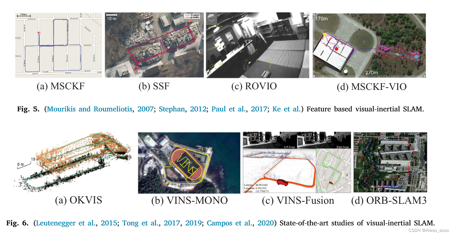
In 2007, Mourikis and Roumeliotis (2007) proposed the multi-state constrained Kalman filter (MSCKF), which is the earliest well-known visual-inertial SLAM system based on the extended Kalman filter (EKF) algorithm. Compared with pure visual odometry, MSCKF (Fig. 5(a)) can adapt to more severe motion and texture loss within a certain time, with higher robustness. In 2012, Stephan (2012) proposed SSF (Fig. 5(b)), which is a single-sensor and multi-sensor fusion framework based on time delay compensation of loosely coupled EKF method. In 2013, Li and Mourikis (2013) pointed out the inconsistency of MSCKF in the state estimation process. In 2017, Paul et al. (2017) proposed MSCKF2.0, which has greatly improved its accuracy, consistency and computational efficiency. In addition, ROVIO (Robust Visual Inertial Odometry) (Bloesch et al., 2015) (Fig. 5(c)) and MSCKF-VIO (Ke et al.) (Fig. 5(d)) are also excellent works based on filtering methods in recent years.
3.2.2. Optimization-based methods
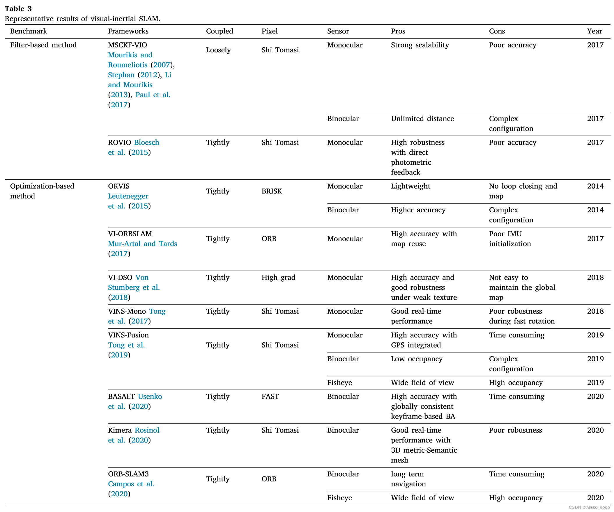
In terms of optimization-based VI-SLAM systems, the most classic frameworks are OKVIS (Open Keyframe-based Visual-Inertial SLAM) (Leutenegger et al., 2015) (Fig. 6(a)) and VINS-Mono, 106 (Fig. 6(b) )). In 2015, Leutenegge et al. proposed OKVIS, which uses IMU measurements to predict the current state, spatial points, and 2D image features to constitute reprojection errors. The predicted IMU state quantities and optimized parameters constitute the IMU error term, and then the reprojection error is combined with the IMU error term for optimization. In 2017, Tong et al. (2017) proposed VINS-Mono, which is considered to be an excellent monocular VI-SLAM system, in which the optical flow method is used in the front end, and the nonlinear optimization algorithm based on sliding windows is used in the back end (Cheng et al. , 2021b). In addition, the initialization method of VINS-Mono is worth noting, which uses the disjoint method (as well as VI-ORBSLAM Mur-Artal and Tards, 2017), first initialize the vision-only subsystem, and then estimate the IMU (accelerometer and gyroscope) bias, gravity, scale and velocity. Tested on KITTI and EuRoC datasets, VINS-Mono is proven to have comparable positioning accuracy to OKVIS, and is more complete and robust in the initialization and loop-closing stages. In 2019, the VINS-Mono team proposed a binocular version with integrated GPS information, namely VINS-Fusion (Tong et al., 2019). As shown in Figure 6(c), due to the addition of GPS measurement, good positioning and mapping results have been achieved in outdoor environments, and are also considered to have good applications in the field of autonomous vehicles. In 2020, Campos et al. (2020) proposed a feature-based tightly integrated visual-inertial SLAM system, ORB-SLAM3. It is the latest effort, enabling a more efficient initialization process through the Maximum A Posteriori (MAP) algorithm, and implementing a multi-map feature that relies on a new approach to place recognition with improved recall. Additionally, the system is capable of performing visual, visual-inertial, and multi-map SLAM with monocular, binocular, and RGB-D cameras. Experimental results for outdoor scenes are shown in Fig. 6(d). The pipeline of ORB-SLAM3 is similar to ORB-SLAM2, and the whole system consists of three threads. Tracking, partial mapping, and loop closing (i.e. loop and map merging) threads. In addition, ORB-SLAM3 can survive for a long time with poor visual information, and when it gets lost, it will start a new map that will seamlessly merge with the previous map when revisiting the mapped area. Table 3 summarizes the main algorithms in the visual-inertial SLAM framework in recent years. At present, the optimization-based VI-SLAM method has become the mainstream. Besides the above methods, there are other state-of-the-art works that can be summarized as follows, but not limited to BASALT, Kimera, ICE-BA, Maplab, StructVIO. RKSLAM. VI-SLAM systems based on event cameras can be listed as follows, but are not limited thereto. Deep learning based approaches can be seen in Jared Shamwell et al. (2019), which present a network that performs VIO without IMU intrinsic parameters or extrinsic calibration between IMU and camera. The literature (Lee et al., 2019) provides a network to avoid calibration between camera and IMU sensors. See in Shamwell et al. (2019), which demonstrate a network that performs VIO without IMU intrinsic parameters or extrinsic calibration between IMU and camera. The literature (Lee et al., 2019) provides a network to avoid calibration between camera and IMU sensors. See in Shamwell et al. (2019), which demonstrate a network that performs VIO without IMU intrinsic parameters or extrinsic calibration between IMU and camera. The literature (Lee et al., 2019) provides a network to avoid calibration between camera and IMU sensors.
 The latter is the slam combined with vision-radar-imu, which is not listed. If you are interested, you can read the original paper.
“4. Discussions”
Although visual SLAM has achieved great success in localization and mapping of autonomous vehicles, as mentioned earlier, existing technologies are not yet mature enough to fully address the problem at hand. Vision-based localization and mapping solutions are still in their infancy. To meet the requirements of autonomous driving in complex urban environments, future researchers face many challenges. The practical application of these techniques should be considered a systematic research question. In addition, the SLAM system is only a component of the complex system of the self-driving car. The self-driving system cannot completely rely on the SLAM system, but also needs to be equipped with modules such as control, target detection, path planning, and decision-making. In this section, we make some overall observations and inferences about the key issues and future development trends of vision and vision-based SLAM in autonomous vehicle applications. In this section, we discuss some key issues of vision and vision-based SLAM in autonomous vehicle applications today, as well as future development trends.
(a) Real-time performance. Autonomous vehicle applications require visual SLAM systems to react as quickly as possible. In the case of vision algorithms, a frequency of 10 Hz is considered to be the minimum desired frame rate for a vehicle to maintain autonomous driving on urban roads (Bojarski et al., 2016). On the one hand, some vision algorithms have been proposed to explicitly optimize real-time performance (Jaimez et al., 2017; Holzmann et al., 2016), on the other hand, they can be implemented by hardware with higher specification performance such as graphics processing unit (GPU). Further improvements. Furthermore, various environmental dynamics such as scene changes, moving obstacles, and illumination invariants should be taken into account for system accuracy and robustness (An et al., 2017; Kim and Kim, 2016; Liu et al., 2017). ). Currently, cameras are mostly used for obstacle detection or avoidance and lane keeping for autonomous driving in specific scenarios, such as autonomous valet parking (APV) (Lovegrove et al., 2011).
(b) Positioning: Autonomous driving in urban road scenes is still in the technical research stage of L2 and L3. One of the key problems is that the positioning accuracy of vehicles is relatively rough. We observed that high-quality autonomous driving is inseparable from precise location, even in an environment without a map, the vehicle must navigate, accurate to the centimeter level. This kind of accuracy cannot be achieved by traditional GPS receivers alone, which have an accuracy of about 10 meters, and usually require the installation of expensive differential GPS (DGPS) receivers to achieve, but it introduces redundancy, while the visual SLAM algorithm itself can used for precise positioning. As reviewed in this paper, other GPS-independent methods are investigated to achieve relative localization, such as vision-inertial fusion methods (Section 3.2), vision-LiDAR fusion methods (Section 3.3), and vision-LiDAR-IMU Fusion methods (Section 3.4). As far as visual-inertial fusion methods are concerned, unless the IMU is highly accurate, the drift error introduced by the IMU will affect the accuracy exponentially. As far as the vision-lidar fusion approach is concerned, the localization robustness of autonomous vehicles cannot be guaranteed due to the lack of own inertial navigation (DR) sensors such as encoders and IMU sensors. In terms of vision-lidar-IMU fusion methods, as far as we know, there is no mature vision-based fusion SLAM algorithm successfully applied to autonomous vehicles in the real world, but many excellent fusion methods are being used in recent years. Research. As the cost of lidar sensors decreases, we believe that the vision-lidar-IMU fusion approach is the ultimate solution for high-precision localization of autonomous vehicles.
(c) Testing: Currently, real-world implementation is inadequate, which can be attributed to local legislation and the lack of development vehicles for autonomous driving testing. Here, we observe that almost all recently proposed visual SLAM works are tested on public datasets (such as KITTI, EuROC, TUM, etc.). Admittedly, these datasets are great for algorithm validation, but how well these algorithms will ultimately perform in real-world environments remains to be seen. Furthermore, testing on these datasets also limits the testing environment to where the dataset captures, and it may not be a valid indicator of these algorithms in other countries or cities. Another reason for the lack of real-world implementation appears to be due to the high computational requirements of visual SLAM algorithms, suggesting that an online implementation would require a computer with sufficient and dedicated parallel processing hardware. Common mobile computers, such as laptops, do not have the parallel computing capabilities of desktop GPUs. Commercial self-driving computers such as Nvidia's DRIVE PX2 (NVIDIA Corporation, 2017a) are very expensive and generally unaffordable for development projects with limited budgets. It is encouraging to see the recent emergence of high-performance and low-cost embedded devices with improved vision algorithms such as the Nvidia Jetson (NVIDIA, 2017b) and the optimization of fast VO (i.e. front-end or part of visual SLAM) methods (Jaimez et al., 2017; Jaimez and Gonzalez-Jimenez, 2015; Steinbrcker et al., 2011; Sun et al., 2018; Wu et al., 2017) can catalyze these realizations.
(d) Future development trends. Due to the complex modules of visual SLAM (such as front-end, back-end, closed-loop and mapping, etc.), which increase the computational burden of the hardware platform, high-performance mobile computing platforms often limit the application of the above-mentioned visual SLAM algorithms in autonomous driving. Multi-agent based visual SLAM techniques seem to be able to overcome this problem. At present, multi-agent-based visual SLAM is usually used for aerial drones. If it is installed on an autonomous vehicle for mobile computing, the mobile computer platform is only responsible for processing the front-end data, while the process of back-end optimization and mapping is performed by a remote server through 5G /6G communication network to transmit data to solve the problem, we believe this will greatly accelerate the application of visual SLAM in future autonomous driving vehicles.
5 Conclusion
Recent research has contributed greatly to addressing the problem of visual SLAM. This work reviews various types of visual SLAM and/or vision-based SLAM methods, and their applications in autonomous driving. Currently, the application of visual SLAM in self-driving cars is considered immature, but it still attracts a lot of attention. Due to the easy availability of public datasets for autonomous driving, visual SLAM algorithms are always easy to validate and research on new algorithms is encouraged. However, although the availability of datasets facilitates the proposal of new visual SLAM algorithms, current real-world visual SLAM applications in urban road environments are still deficient. Furthermore, evaluation results on datasets often deviate from a complete indication of performance in local real environments, so a practical visual SLAM is expected to emerge in autonomous vehicle applications. By reviewing the most advanced visual SLAM algorithms, it can be confirmed that the current development trend of visual SLAM systems tends to be lightweight and multi-agent cooperation, which encourages applications to low-power hardware such as embedded devices, and multi-sensor fusion algorithms are considered to be the core of visual SLAM At the heart of applications in self-driving cars. To sum up, there are still various problems in the field of autonomous driving, especially the combination of visual SLAM and autonomous vehicles needs to be explored. However, the increasing public acceptance of self-driving cars and the emergence of high-performance mobile computers will undoubtedly inspire the practical application of visual SLAM in the near future.
Article link:
 https://reader.elsevier.com/reader/sd/pii/S0952197622001853?token=E53610F0BCFD8EF8FA5D6121585F3CB04CA0EEE3D62FF04769C12D5164AFB8C373D18BDD768347A3A6C5924ED1BF4292&originRegion=us-east-1&originCreation=20220625125045