Introduction
This article is based on a summary of the basic knowledge related to GNSS positioning in "SLAM Technology in Autonomous Driving and Robots" for memo purposes.
Organize knowledge points
-
GNSS (Global Navigation Satellite System) positioning principle
GNSS determines its position by measuring the distance between itself and the satellites around the earth, and the distance from the satellites is mainly measured by time Determined by interval -
The relationship between GNSS and GPS
GPS (Global Positioning System) is a type of GNSS, developed by the United States. In addition, there are China's Beidou positioning system BDS, Russia's GLONASS, and the European Union's Galileo system (GALILEO) -
The relationship between real-time dynamic differential technology (RTK) and GNSS
- RTK is a technology that corrects the positioning error of satellite signals during transmission and improves positioning accuracy.
- The main principle of RTK: communicating with the vehicle through a base station on the ground with a known precise position, correcting the signal of the vehicle satellite receiver
-
Differential positioning classification
Position differential positioning, pseudo-range differential positioning, carrier phase differential positioning (RTK) -
Principle of position differential positioning
The simplest differential method. First, the GNSS receiver installed at the base station receives information from four satellites, calculates its own three-dimensional position, and compares it with the real position to obtain an error. The user computer also receives information from the four satellites, calculates the position, and then subtracts the error to obtain the corrected coordinates.
The principle is that the position error calculated by the base station is the same as the position error calculated by the user machine -
Pseudo-range differential positioning principle
The base station calculates the distance 1 between it and its own visible satellite (without error or the error is relatively small), and compares the distance 1 with the measured value 2 containing the error. Compare and use aα-βfilter to filter the difference to obtain the error value. The user machine subtracts this error from the calculated position to obtain its own position, thus eliminating the common error. The best pseudo-range difference can achieve sub-meter positioning accuracy. -
Principle of Carrier Phase Differential Positioning (RTK)
When the user is far away from the base station, the effects of the above two differential technologies decrease.
The satellite signal received by the base station is sent to the user in real time through the wireless communication network. The user receiver jointly solves the received satellite signal and the received base station signal in real time to obtain the base station and Inter-rover coordinate increment -
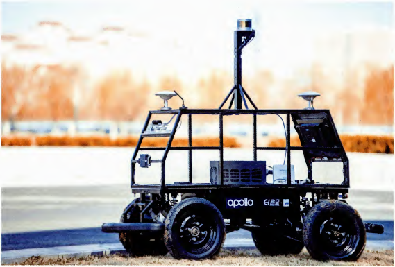
Calculation of vehicle orientation via two RTK receivers

By subtracting the position vectors of the main and auxiliary antennas, we obtain the direction between the two antennas and then obtain the vehicle angle (mainly the heading angle yaw)
Generally, the rear side of the vehicle or The antenna on the left serves as the main antenna -
External parameters of RTK equipment
- Baseline: the distance between two antennas
- Installation declination angle: rotation of the two antenna coordinate systems
- Installation offset: the position offset of the two antennas
-
Common coordinate systems
- Geographic coordinate system: also called longitude and latitude coordinate system or longitude and latitude high coordinate system, the geographical coordinate system is the world coordinate system
- UTM coordinate system: Metric coordinates are used. Due to the distortion of the earth's projection, there is a multiple relationship of 0.9996 between the actual UTM coordinates and the metric coordinates.
- Northeast sky (X-east, Y-north, Z-sky), ENU
- North East (X-north, Y-east, Z-center of the earth), NED, this is the coordinate system commonly used by inertial navigation manufacturers.
- Conversion between the northeast azimuth angle h and the northeast azimuth angle h’: h’=-h + pi/2
-
Conversion between UTM coordinates and vehicle coordinates
- The general form of UTM coordinates is: 11U 358657mE 5885532mN
- 11 represents the longitude area
- E represents the dimension area
- 358657mE means that the eastward position is 358657m
- 5885532mN means the north direction position is 5885532m
- UTM 栐标为 T W G T_{WG} TWG, W represents the world system, G represents the GNSS system, and the UTM coordinates need to be transformed into vehicle coordinates T W B T_{WB} TWB
- There is an external parameter transformation from UTM coordinates to vehicle coordinates, T G B T_{GB} TGB,则有 T W B = T W G ∗ T G B T_{WB} = T_{WG} * T_{GB} TWB=TWG∗TGB
- The general form of UTM coordinates is: 11U 358657mE 5885532mN