output mode
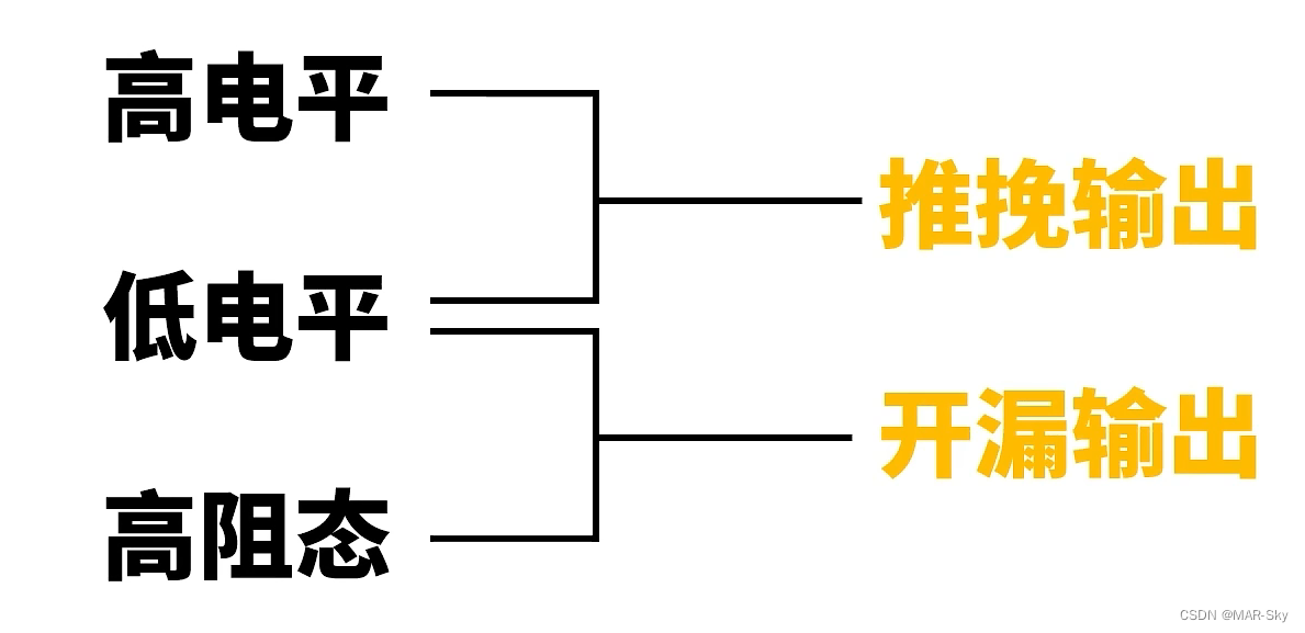
Several output situations
Reference: https://www.bilibili.com/video/BV1D84y1c7GV/?spm_id_from=333.999.0.0&vd_source=00bd76f9d6dc090461cddd9f0deb2d51
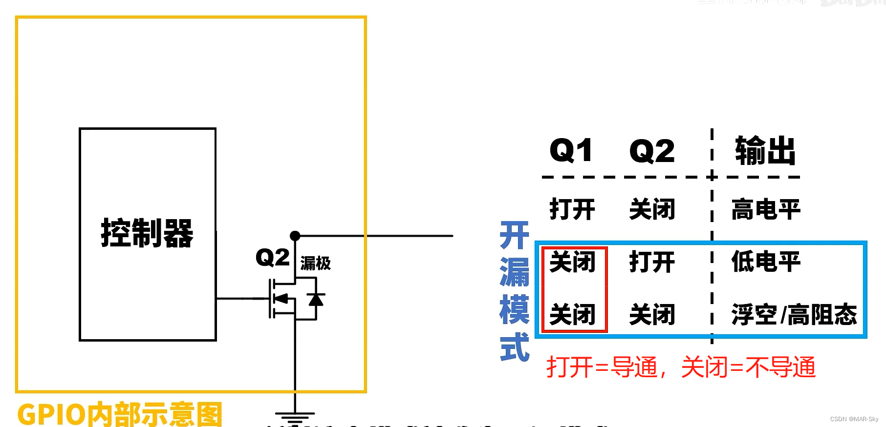
The following is an internal structure circuit of output IO,
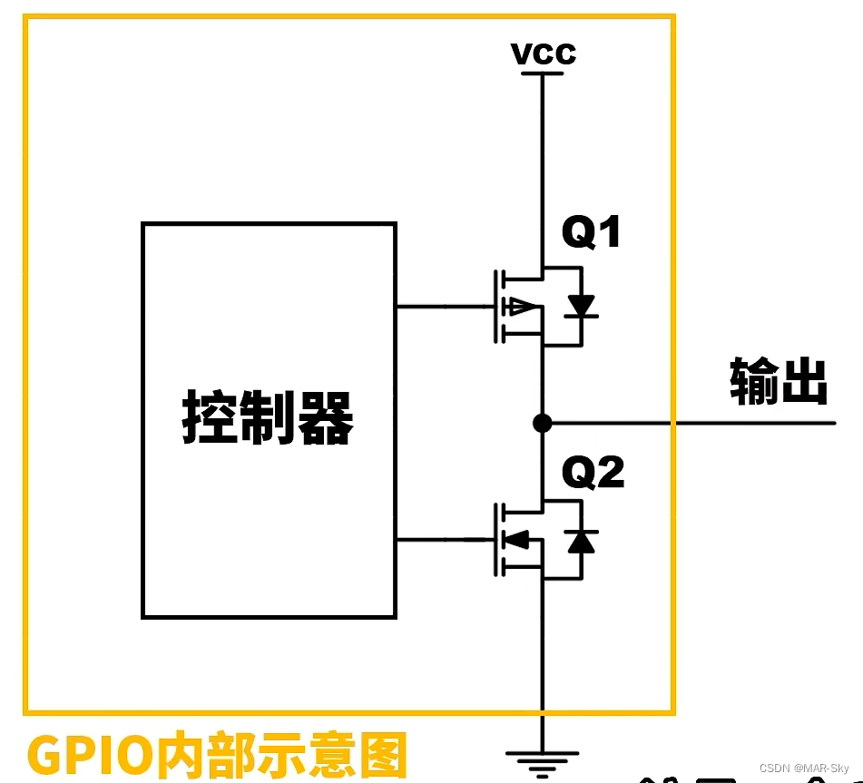
as shown in the figure, the output mode of GPIO is controlled by two mos tubes, However, Q1 and Q2 cannot be turned on at the same time, otherwise the current will be too large.
| Switch Q1 | Switch Q2 | status description |
|---|---|---|
| turn on | non-conductive | output high level |
| non-conductive | turn on | low level |
| non-conductive | non-conductive | Floating/high impedance state |
push-pull output
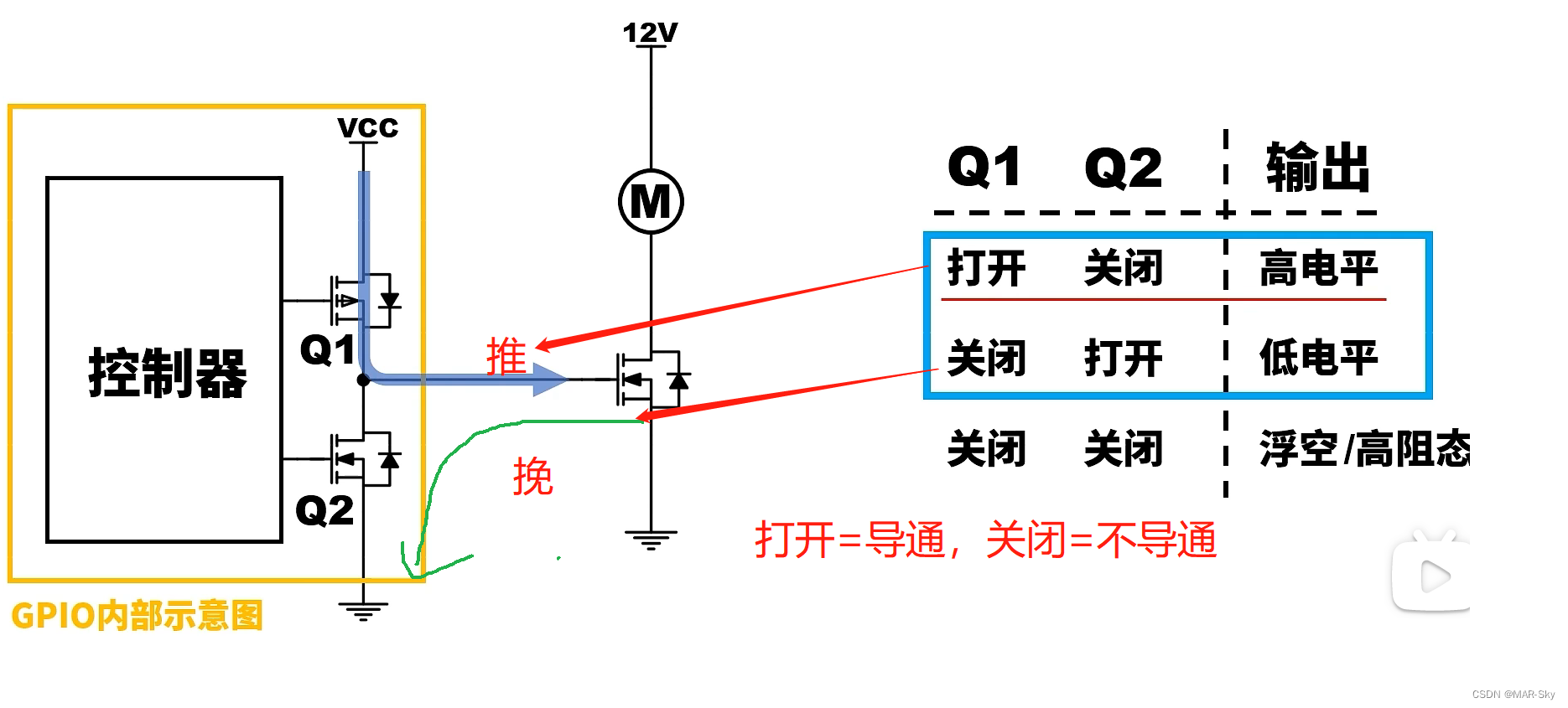
When the output is high level, current will flow from the IO port, which is called push; when the output is low level, there will be external current flow to the IO port, which is called pull.
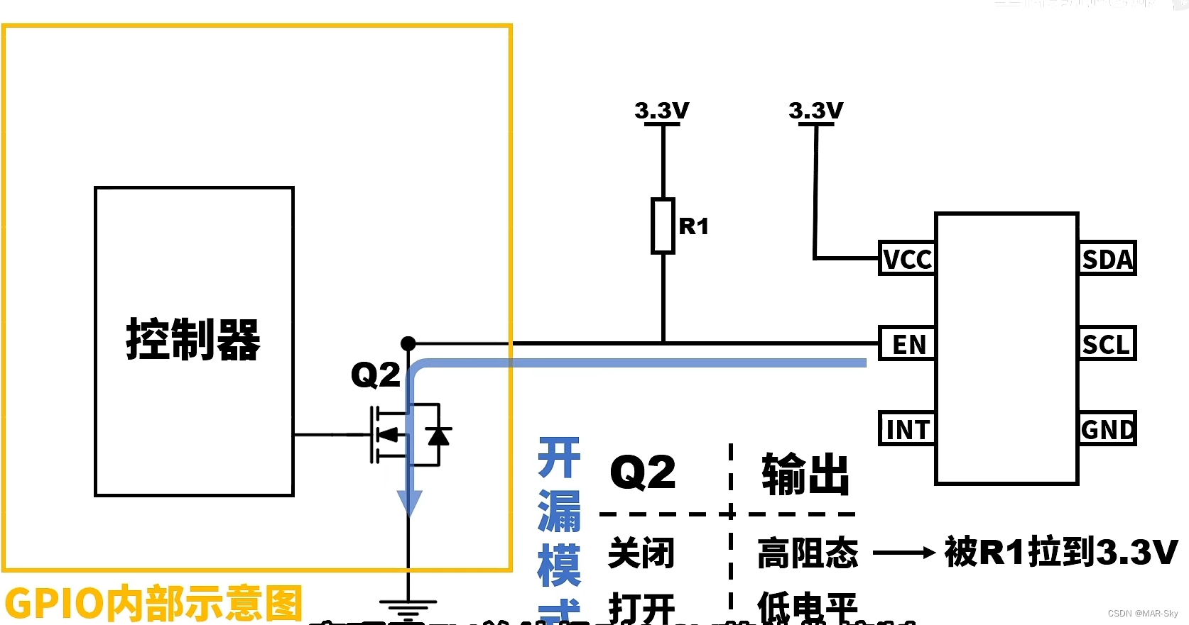
open drain output
When Q1 is always closed, it is found that only Q2 works, and the output is a drain port of Q2 that is not connected to anything, so it is called open-drain output . What this does is,
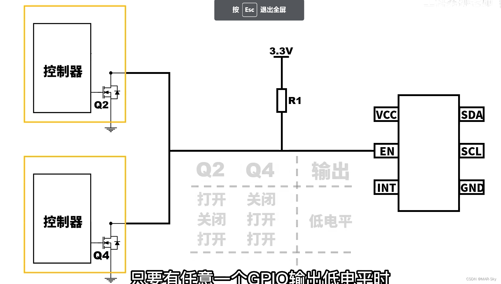
1. It can control the external interface of different voltages, just as a control switch
As shown in the figure below, external input ports with different voltages can be controlled. The 3.3v power supply can be configured externally, without requiring the MCU itself to be 3.3v.
2. Several IO ports can control a state
Either of these two IO ports can be turned on to control the input to be low.