STM32 PWM working process


Take channel 1 as an example:

CCR1: Capture comparison (value) register (x=1,2,3,4): Set comparison value.
CCMR1: OC1M[2:0] bits:
For PWM mode, it is used to set PWM mode 1 [110] or PWM mode 2 [111]
CCER: CC1P bit: input/capture 1 output polarity. 0: High level is valid, 1: Low level is valid.
CCER: CC1E bit: input/capture 1 output enable. 0: off, 1: on.
PWM Mode 1 & PWM Mode 2


void TIM_OC2PreloadConfig(TIM_TypeDef* TIMx, uint16_t TIM_OCPreload);
void TIM_ARRPreloadConfig(TIM_TypeDef* TIMx, FunctionalState NewState);
STM32 timer 3 output channel pin

PWM output library function
void TIM_OCxInit(TIM_TypeDef* TIMx, TIM_OCInitTypeDef* TIM_OCInitStruct);

Set comparison value function:
void TIM_SetCompareX(TIM_TypeDef* TIMx, uint16_t Compare2);
Enable output compare preloading:
void TIM_OC2PreloadConfig(TIM_TypeDef* TIMx, uint16_t TIM_OCPreload);
Preload register enable bit to enable auto-reload:
void TIM_ARRPreloadConfig(TIM_TypeDef* TIMx, FunctionalState NewState);
PWM output experiment:
Use the PWM function of timer 3 to output a PWM wave with a variable duty cycle to drive the LED light, so that the brightness of the LED [PB5] changes from dark to bright, and then from bright to dark, and so on.
PWM output configuration steps:
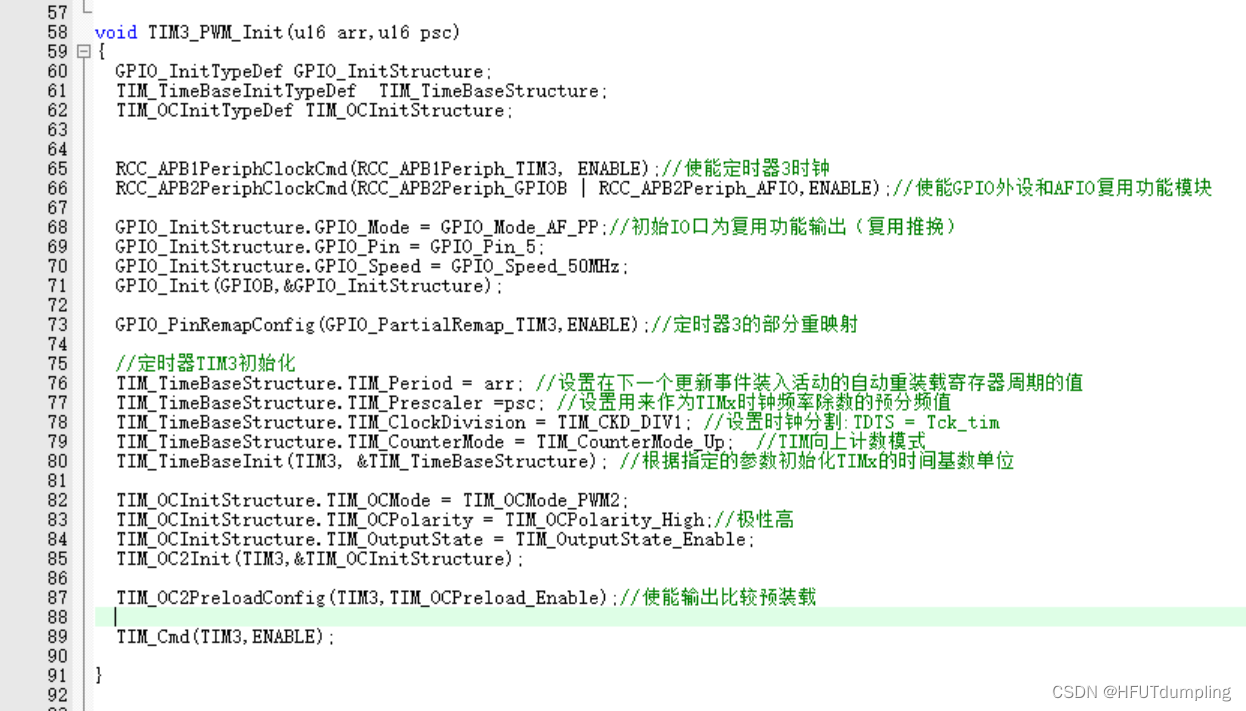
Enable timer 3 clock: RCC_APB1PeriphClockCmd();
Enable GPIOB clock: RCC_APB2PeriphClockCmd();
②Initialize the IO port as a multiplex function output. Function: GPIO_Init ();
GPIO_InitStructure.GPIO_Mode = GPIO_Mode_AF_PP;
③Here we are going to use PB5 as the PWM output pin of the timer, so we need to remap the configuration.
So you need to turn on the AFIO clock. Also set up remapping.
RCC_APB2PeriphClockCmd(RCC_APB2Periph_AFIO,ENABLE);
GPIO_PinRemapConfig(GPIO_PartialRemap_TIM3, ENABLE);
④Initialization timer: ARR, PSC, etc.: TIM_TimeBaseInit ();
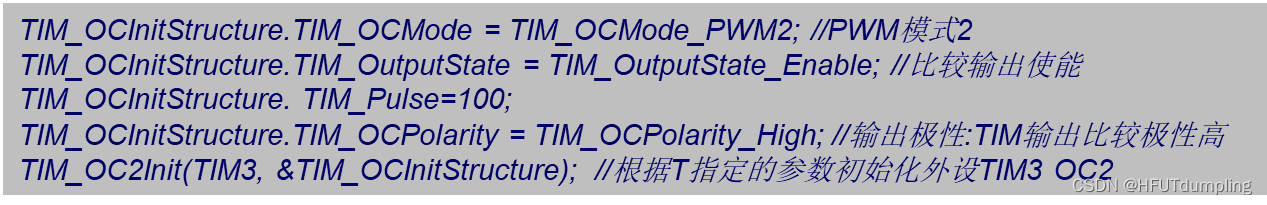
⑤Initialize output comparison parameters: TIM_OC2Init();
⑥Enable preload register: TIM_OC2PreloadConfig(TIM3, TIM_OCPreload_Enable );
⑦Enable the timer. TIM_Cmd ();
⑧Continuously change the comparison value CCRx to achieve different duty cycle effects: TIM_SetCompare2();
Important code:
timer.c:
main.c:

After downloading the program, the red light cycles from dark to bright and from bright to dark.

Summarize
It can only be said that I have a rough understanding of the relevant principles and basic usage of PWM. PWM output will be often used in the later stage, so I hope that I will come back and reorganize the content of this part after learning the following content!