content
foreword
I'm ashamed to say that I've been studying microcontrollers for so long. Until I wrote this article, I didn't fully understand the eight usage modes of GPIO. Before, I just used them stupidly until I finished the analog electricity and math electricity. Today After reviewing this knowledge again, I found that I finally understood the knowledge that I did not understand thoroughly before, so I hereby summarize it.
what is GPIO
From the most basic 51 microcontroller, Arduino, to STM32, Raspberry Pi, etc., there will be a concept of GPIO port on these. If you click on my blog, it means that you have a high probability of starting to learn microcontrollers, then you should understand It is these ports that can output high and low levels, or read the input level on the pin.
The general function of GPIO is as follows
GPIO (general porpose intputoutput): short for general input and output ports. Its output and input can be controlled by software. The GPIO pins of the stm32 chip are connected with external devices, so as to realize the functions of external communication, control and data acquisition.
——— Introduction to GPIO
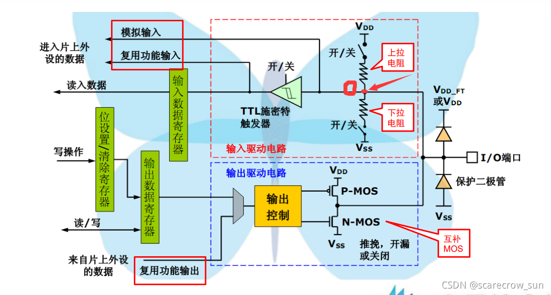
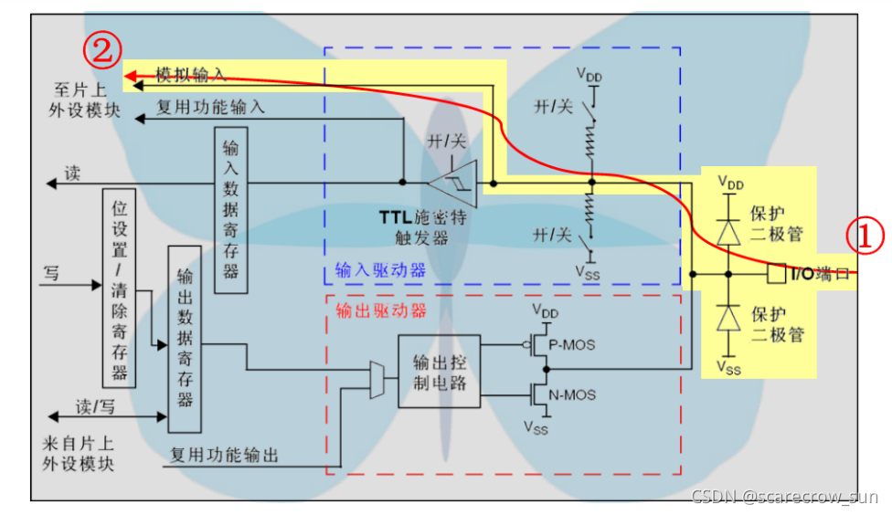
Below is an internal schematic diagram of the STM32 internal GPIO port as an example. Don't worry, everyone. First, there is a concept of this diagram. The following is how to understand the GPIO port.
Let's start with the most basic knowledge
of pull-up and pull-down:
when we close the switch of the pull-up resistor and disconnect the switch of the pull-down resistor, that is, the pull-up path is turned on at this time. According to our most basic circuit knowledge, if the I/O port is disconnected but not connected to the peripheral, or the peripheral is connected but the circuit is also disconnected, when the entire circuit is open, the resistance is equivalent to non-existent, at this time O The potential of the point is clamped to VDD (positive supply voltage), so point O is at a high level.
In the same way, close the switch of the pull-up resistor and disconnect the switch of the pull-down resistor, then when the circuit is disconnected, according to the circuit knowledge, the resistance is equivalent to not exist, and the voltage of point O is clamped at VSS (GND), That is, point O is at a low level.
Digital signal and analog signal
Digital signal: according to some rules, the voltage within a range is specified as 1, and the voltage within a range is specified as 0, that is, a series of 0,1 signals
Analog signal: it is read continuously Voltage value.
Regarding the TTL Schmitt trigger and P-MOS and N-MOS on the figure, we will talk about the corresponding parts later.
Eight modes of GPIO
GPIO can be divided into input or output, adding up to a total of eight modes.
input mode
In the input mode, there are a total of four output modes, which are
- analog input
- pull-up input
- drop down input
- floating input
floating input
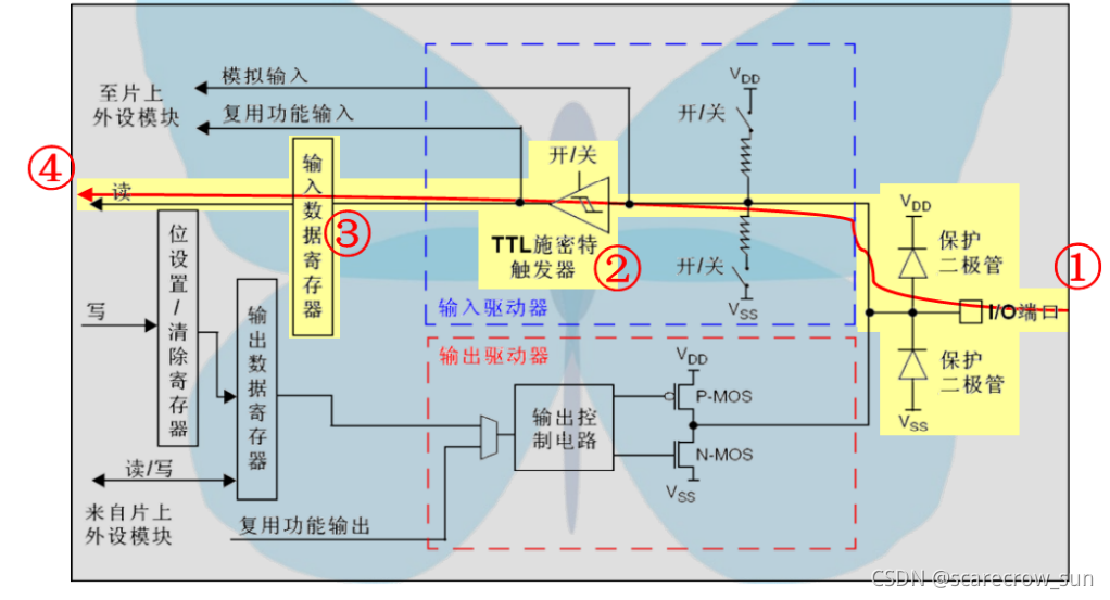
The path that the floating input needs to take is shown in the figure. First of all, you must know that the path taken by the floating output is to read a digital signal.
The required circuit is as follows:
Both switches in the path where VDD and VSS are open simultaneously. There is no pull-up and pull-down at this time, so when the IO port is not connected to an input, the level at this time will be an uncertain value, which is what we call floating. The level will be in a state of transition, one high and one low. It will only be determined if a high/low level is input.
Note : The switches of pull-up and pull-down resistor circuits are generally referred to by MOS tubes instead of switches in practical applications.
Going further ahead is to come to the part of the TTL Schmitt trigger. We know that due to the characteristics of the power supply, or due to the characteristics of the external switch input, the input digital signal is very likely to be affected by noise such as pulses. In order to make our waveform look better or the signal clearer, we set TTL Schmitt trigger this thing. After that, we store this digital information in the input data register.
So we read the digital signal from IO
Advantage : The level of this input mode is completely dependent on the external circuit and has nothing to do with the internal circuit. Sometimes it is used to read the switch keys.
However, when there is no external circuit connected, the floating IO pin will make the level uncertain
pull-up input
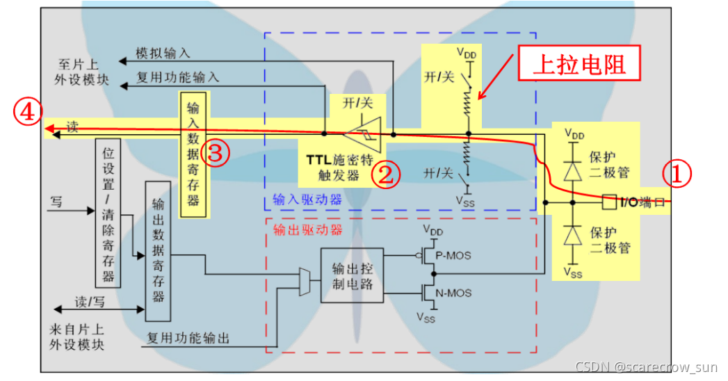
The path that the pull-up input needs to take is shown in the figure. First of all, you must know that the path taken by the pull-up output is to read a digital signal.
The required circuit is as follows:
The switch of the pull-up resistor where VDD is located is closed, and the switch of the pull-down resistor is open.
According to the above mentioned floating input, when there is no signal input, according to the circuit knowledge, the level at this time is the level of VDD, and the level read at this time is the high level. If a high level is input, there is almost no potential difference between VDD and point O (point O in the uppermost figure), and the level of point O is still high at this time, and the read level is high level. However, since the level is also high when there is no voltage input, there is no way to determine whether the signal is input in this input situation.
When the input signal is a low level, the level of the O point will become a low level at this time, then a potential difference is formed between VDD and O point, but because of the existence of the pull-up resistor, it is not A large current will appear. At this time, a level read by the microcontroller is a low level. In the case of the pull-up input, the low level can be very clearly read.
The advantage of the pull-up input is that the input level will not float up and down, causing the input signal to be unstable, and it can be stable at a high level when there is no signal input.
drop down input
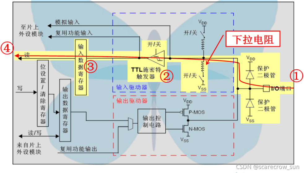
Pull down and enter the path to be taken as shown in the figure. First of all, you must know that the path taken by the pull-down output is to read a digital signal.
The required circuit is as follows:
The pull-up resistor switch where VDD is located is open, and the pull-down resistor switch is closed.
According to the above mentioned floating input, when there is no signal input, according to the circuit knowledge, the level is the level of VSS, and the level read at this time is the low level. At this time, if the input level is a low level, there is no way to distinguish it from the previous situation. But if the input is a high level, a potential difference is also formed between point O and VSS, and the level of point O will become an external high level, then the single-chip microcomputer gets a high level signal.
The advantage of the pull-down input is that the input level will not float up and down, causing the input signal to be unstable, and it can be stabilized at a low level when there is no signal input.
analog input
The path that the analog input needs to take is shown in the figure. First of all, we have to know that the path taken by the analog output is that we need to read an analog signal.
When we use a microcontroller, we sometimes need to use AD to collect the real voltage on the IO port. This has the analog input we need. In order to actually read the external voltage to the AD module of the microcontroller, we can neither close the pull-up and pull-down switches, nor allow the signal to pass through the Schmitt trigger.
Advantage : Allows AD to read voltage. It can also run in low power mode to save power.
output mode
In the output mode, there are also four output modes, which are
- Open drain output
- Push-pull output
- Multiplexed open-drain output
- Multiplexed push-pull output
Open drain output
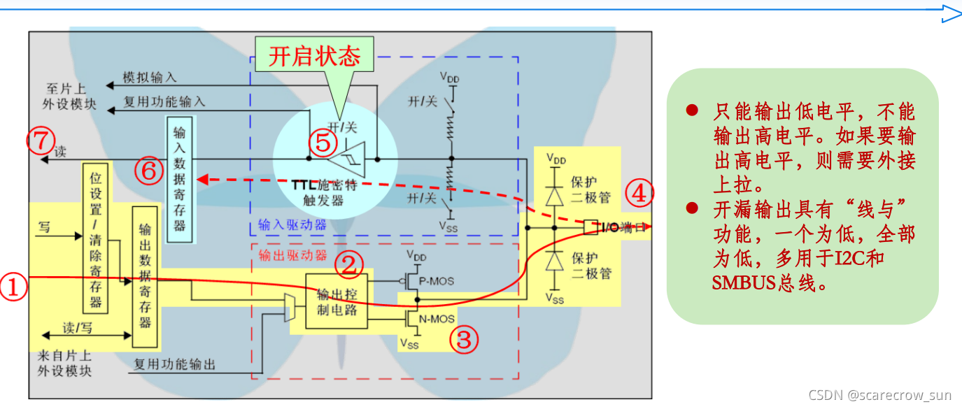
④⑤⑥⑦ is the process of reading, which is ignored here.
The circuit path of the open-drain output is ①②③④, and the previous steps in ② are a control of the output signal, not the key point. The most important thing in the open-drain output is ③, which is the part of N-MOS. Let’s supplement the knowledge of mode electricity.
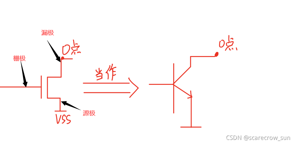
We can think of this MOS tube as a triode. For the triode shown in the figure, we can simply understand it as a faucet. The left side is a faucet switch. When a high level is given, the O point and GND are connected. will turn on. (The output of point O is the output of an inverter, that is, the level of point O will be opposite to the gate of the left MOS (the base of the triode),
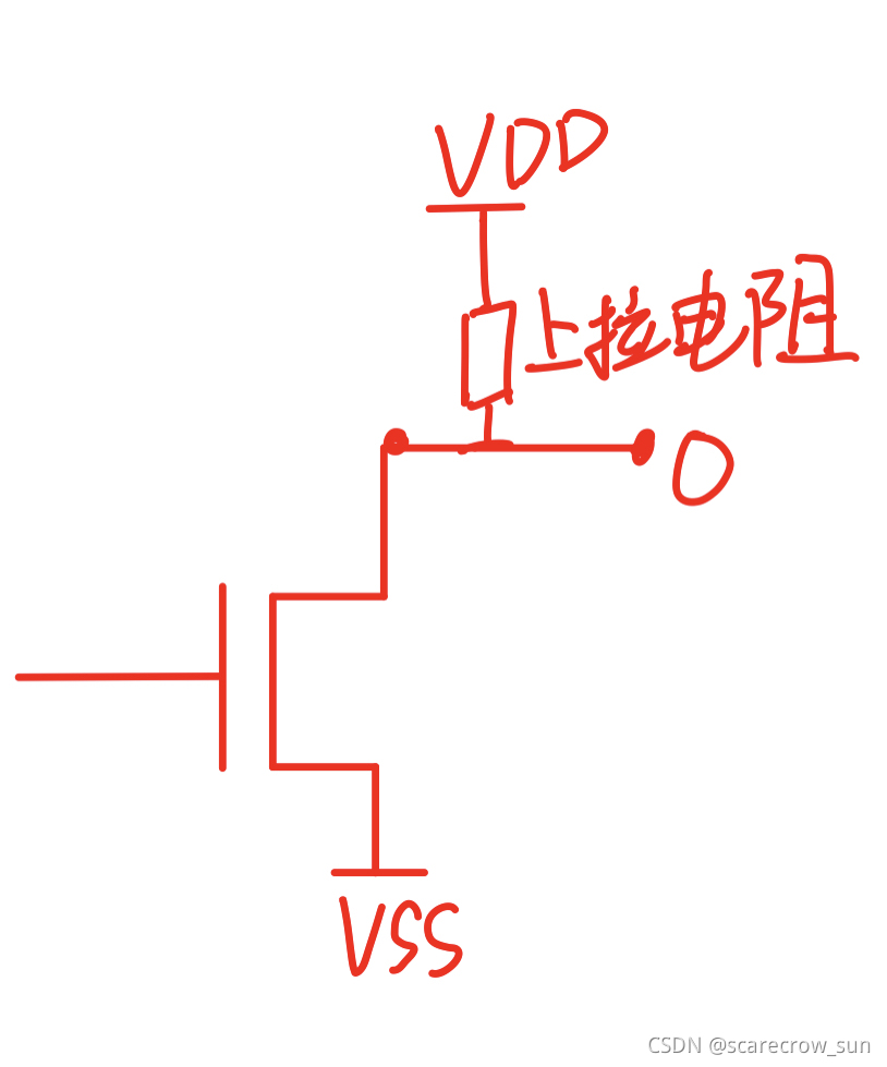
so the open-drain output is easy to understand. When we give a low level, the MOS tube is turned off, and the output voltage at this time is a floating, that is, an uncertain voltage. If a high level is given, then the MOS tube is turned on, which is equivalent to connecting the IO port to the VSS, and a low-level voltage is output here.
Advantages ①
Although we can see that there is no way for the open-drain output to output a high level internally, this one seems to be a disadvantage. It's actually an advantage. We can get that when a low level is given, the MOS tube is not turned on, and the voltage is uncertain at this time, which makes it impossible to output a high level, but once we add a pull-up externally, then this shortcoming will be effectively avoided. . And, because we designed a pull-up by ourselves, the voltage of this pull-up is determined by ourselves, so that we can give this pull-up voltage according to the high level of V required by the external circuit , which can be better adapted. More situations. As shown in the figure below, we can give any VDD voltage to suit our actual needs.
Advantages ②
The essence of the open-drain output is actually an OD gate (OD: Open Drain). In digital power, a very important feature of the OD gate is that it can realize the function of line AND. In short, in a bus protocol like IIC, as long as one of them is low, the bus will be pulled low. .
Push-pull output
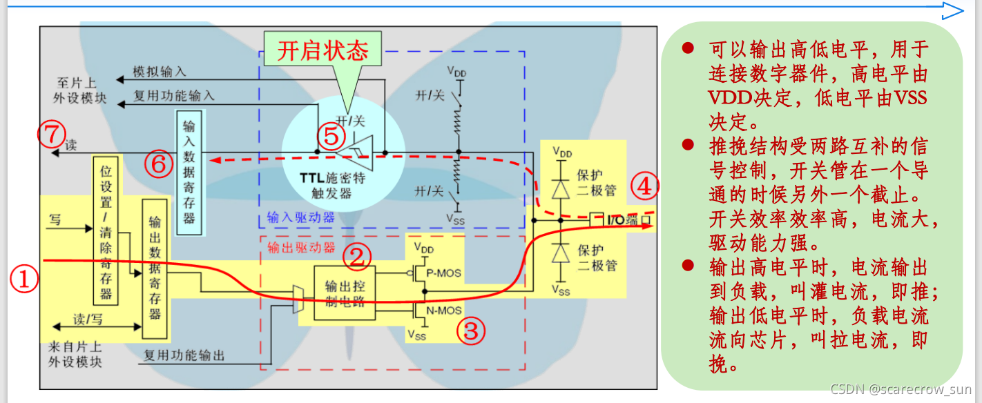
Push-pull output means that two different MOS tubes can be used to realize the output.
P-MOS and N-MOS are different control methods. When a high level is given, N-MOS is turned on, and P-MOS is not turned on. At this time, the IO port is connected to VSS, and the output is low. level. When a low level is given, the P-MOS is turned on, and the N-MOS is turned on. At this time, the IO port is connected to the VDD power supply, and the output is a high level at this time.
Be sure to turn this MOS management into a switch-controlled faucet! ! !
Advantages
Strong load capacity.
Multiplexed open-drain output
Multiplexing push-pull and multiplexing open-drain is actually very simple. After you understand the principles of open-drain and push-pull, if you do not want to use the internal output of the microcontroller, then you can multiplex and transfer the output to other peripherals.
Multiplexed push output
GPIO output rate
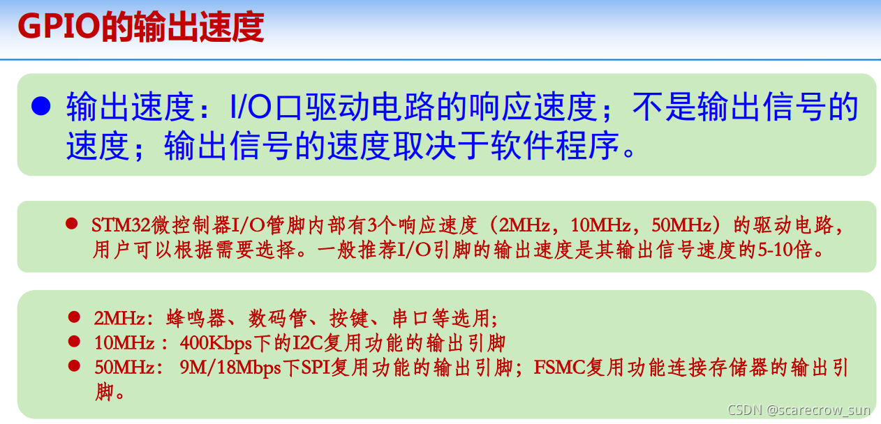
GPIO also has a very important concept, that is, the response speed. The corresponding speed refers to how much time it takes to change when your level needs to be changed. If you are very strict with this time requirement, then you must use the IO port with high output rate. The opposite is true.