Divided into three steps 1. Turn on the RCC clock corresponding to GPIOx 2. Turn on the output mode rate of the pin 3. Send the level signal through the ODR data register
1. Open the GPIOB port clock
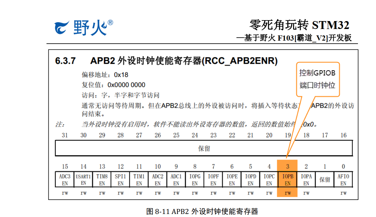
1 // Turn on the GPIOB port clock
2 RCC_APB2ENR | = (1 << 3);
Second, the output mode rate of the open pin
First, we connected to the LED lamp GPIO pins PB0 configured to output mode, i.e., the configuration GPIO port feature
set low register the CRL , see Figure 8-9 . The CRL contains pins 0-7 , and each pin occupies 4 register bits.
The MODE bit is used to configure the output speed, and the CNF bit is used to configure various input and output modes. Here we PB0 feature
set common push-pull output, the output speed is 10M , specific see Listing 8-4

1 // Clear the port bit of control PB0
2 GPIOB_CRL & = ~ (0x0F << (4 * 0));
3 // Configure PB0 as a general push-pull output with a speed of 10M
4 GPIOB_CRL | = (1 << 4 * 0 );
3. Control pin output level
In the output mode, write the parameters to the port bit setting / clearing register BSRR register, port bit clearing register BRR and
ODR register to control the level state of the pin, in which the operation BSRR and BRR ultimately affect the
ODR register, then Then control the GPIO through the output of the ODR register . For one step, we are here directly connected to the operating ODR register to control the GPIO level. See code listing 8-5 for details .
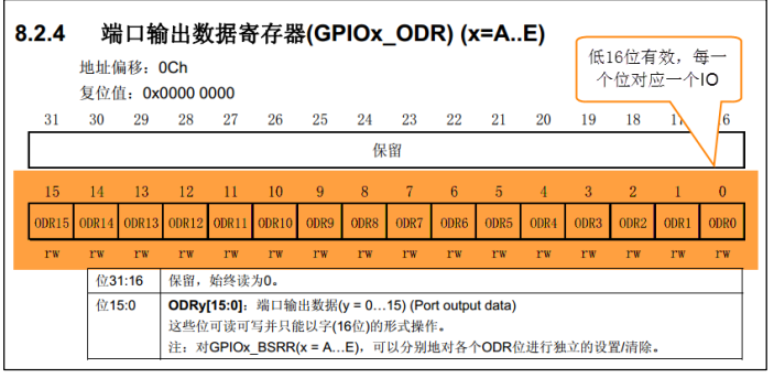
1 // PB0 output low level
2 GPIOB_ODR & = ~ (1 << 0);