1. 初始化流程

2. 在main函数中编写整个初始化流程
/*
 * Copyright (c) 2006-2019, RT-Thread Development Team
 *
 * SPDX-License-Identifier: Apache-2.0
 *
 * Change Logs:
 * Date           Author       Notes
 * 2019-09-09     Mculover666    first version
 */

#include <rtthread.h>
#include <board.h>
#include <rtdevice.h>

#include <drv_soft_i2c.h>
#include <drv_soft_i2c2.h>
#include <u8g2_port.h>
#include <arpa/inet.h>         /* 包含 ip_addr_t 等地址相关的头文件 */
#include <netdev.h>            /* 包含全部的 netdev 相关操作接口函数 */
#include <ntp.h>

#define DBG_TAG "main"
#define DBG_LVL DBG_LOG
#include <rtdbg.h>

#define OLED_I2C_PIN_SCL                    48  // PD0
#define OLED_I2C_PIN_SDA                    49  // PD1

#define LED1_PIN    GET_PIN(B, 0)
#define LED2_PIN    GET_PIN(B, 7)
#define LED3_PIN    GET_PIN(B, 14)

extern int sht30_collect(void);
extern int mqtt_emqx(void);

u8g2_t u8g2;

int main(void)
{
    int count;
    /* set LED pin mode to output */
    rt_pin_mode(LED1_PIN, PIN_MODE_OUTPUT);
    rt_pin_mode(LED2_PIN, PIN_MODE_OUTPUT);
    rt_pin_mode(LED3_PIN, PIN_MODE_OUTPUT);

    //蓝色灯亮,表示在配置状态
    rt_pin_write(LED1_PIN, 0);
    rt_pin_write(LED2_PIN, 1);
    rt_pin_write(LED3_PIN, 0);

    //OLED显示提示信息
    // Initialization
    u8g2_Setup_ssd1306_i2c_128x64_noname_f( &u8g2, U8G2_R0, u8x8_byte_sw_i2c, u8x8_rt_gpio_and_delay);
    u8x8_SetPin(u8g2_GetU8x8(&u8g2), U8X8_PIN_I2C_CLOCK, OLED_I2C_PIN_SCL);
    u8x8_SetPin(u8g2_GetU8x8(&u8g2), U8X8_PIN_I2C_DATA, OLED_I2C_PIN_SDA);

    u8g2_InitDisplay(&u8g2);
    u8g2_SetPowerSave(&u8g2, 0);

    //display
    u8g2_ClearBuffer(&u8g2);
    u8g2_SetFont(&u8g2, u8g2_font_ncenB08_tr);
    u8g2_DrawStr(&u8g2, 1, 12, "IP:     122.51.89.94");
    u8g2_DrawStr(&u8g2, 1, 24, "Port:  1883");
    u8g2_DrawStr(&u8g2, 1, 36, "SSID: ABCDEF");
    u8g2_DrawStr(&u8g2, 1, 48, "Connecting...");
    u8g2_SendBuffer(&u8g2);

    //获取网卡对象
    struct netdev* net = netdev_get_by_name("esp0");

    //阻塞判断当前网络是否正常连接
    while(netdev_is_internet_up(net) != 1)
    {
     rt_thread_mdelay(1000);
    }
    //提示当前网络已就绪
    rt_kprintf("network is ok!\n");

    //NTP自动对时
    time_t cur_time;
    cur_time = ntp_sync_to_rtc(NULL);
    if (cur_time)
    {
      rt_kprintf("Cur Time: %s", ctime((const time_t*) &cur_time));
    }
    else
    {
      rt_kprintf("NTP sync fail.\n");
    }

    //连接MQTT服务器
    mqtt_emqx();

    //display
    u8g2_ClearBuffer(&u8g2);
    u8g2_SetFont(&u8g2, u8g2_font_ncenB08_tr);
    u8g2_DrawStr(&u8g2, 1, 12, "time:");
    u8g2_DrawStr(&u8g2, 1, 24, "tempeture:");
    u8g2_DrawStr(&u8g2, 1, 36, "humidity:");
    u8g2_DrawStr(&u8g2, 1, 48, "lightness:");
    u8g2_DrawStr(&u8g2, 1, 48, "air:");
    u8g2_SendBuffer(&u8g2);

    //启动三个传感器线程
   // sht30_collect();

    //绿色LED闪烁,表示连接MQTT服务器正常,已就绪
    char timestr[6];
    time_t now;
    struct tm *p;
    int min = 0, hour = 0;

    while (count++)
    {
        /* set LED pin level to high or low */
        rt_pin_write(LED1_PIN, count % 2);

        //更新OLED上的时间
        now = time(RT_NULL);
        p=gmtime((const time_t*) &now);
        hour = p->tm_hour;
        min = p->tm_min;
        sprintf(timestr, "%02d:%02d", hour, min);
        u8g2_SetFont(&u8g2, u8g2_font_ncenB08_tr);
        u8g2_DrawStr(&u8g2, 70, 12, timestr);
        u8g2_SendBuffer(&u8g2);

        rt_thread_mdelay(5000);
    }

    return RT_EOK;
}

int register_i2c(void)
{
    rt_hw_i2c_init("i2c1", GET_PIN(B,8), GET_PIN(B,9));
    rt_hw_i2c2_init("i2c2", GET_PIN(F,1), GET_PIN(F,0));

    return RT_EOK;
}
//注册到系统中,自动初始化设备
INIT_BOARD_EXPORT(register_i2c);
3. 运行结果
上电后,蓝色LED灯亮起,屏幕上显示MQTT服务器IP、端口、WIFI SSID信息,然后连接MQTT服务器,如图:

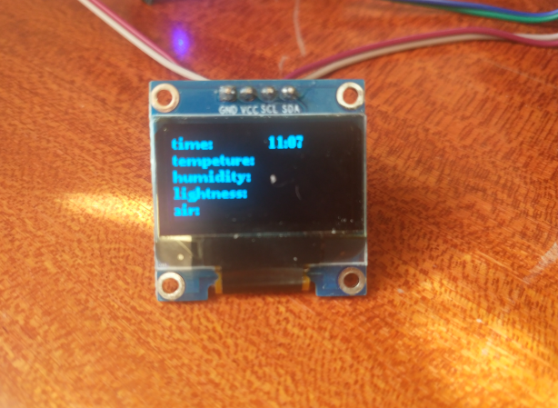
系统成功连接到MQTT服务器之后,进入主界面,由main线程每隔5s刷新一次时间,绿色的LED闪烁,如图:
接收更多精彩文章及资源推送,欢迎订阅我的微信公众号:『mculover666』。