Patch Match Stereo文献+代码
原文来自:PatchMatch Stereo - Stereo Matching with Slanted Support Windows
代码来自:github
1. Patch Match
patch match主要有下面三个步骤。在这里只简单描述一下他们的大概步骤。以备下面在patch match stereo中对比理解。
1.1 初始化
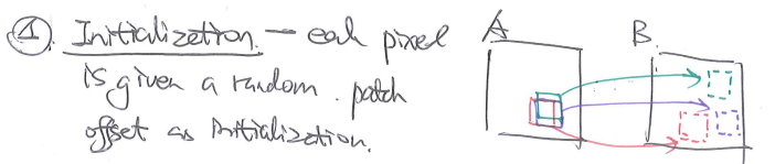
对每一个像素点随机初始化一个reference中的对应的patch。
1.2 传播

这里考虑到的因素是:相邻像素点对应的patch也应该是临近的。并以此来优化像素点的对应patch的位置。
1.3 搜索

最后再进行细致的搜索。
2. Patch Match Stereo
patch match可以解决很多问题,比如图像的补全拉升等等。而这里我们研究patch match stereo,主要解决的是双目估计深度的问题。

它本质是对图片中的每一个像素点(p)都在reference帧中寻找一个对应的平面(f),以最小化cost函数(下图中的m)。

上面展示的是点p和对应的平面f的cost funciton。具体说明见原文。rho和w的定义见下面的说明。
w是平面中每一个点对应的weight。rho对应的像素点之间的相似性计算。
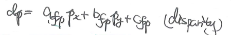
由点的x和y坐标(图像中的col和row)可以计算它落在平面上的话对应的disparity(disparity实际是左右两图的delta x,实际上像素点深度值越大,delta x越大,所以disparity也可以反应出深度,所以下面的方程实际计算z的值)。
2.1 pipeline
结合代码,整个patch match stereo有三个部分:初始化(set),主线处理(process),和后处理优化(postProcess)。
	void PatchMatch::operator()(const cv::Mat3b &img1, const cv::Mat3b &img2, int iterations, bool reverse)
	{
		this->set(img1, img2);
		this->process(iterations, reverse);
		this->postProcess();
	}
2.2 Initialization
2.2.1 初始化weight

每一个像素点(rows * cols个像素点)对应的一个patch的每一个元素(WINDOW_SIZE * WINDOW_SIZE 个元素)都有一个weight。所以weight的size为{rows, cols, WINDOW_SIZE, WINDOW_SIZE}。
		// pixels neighbours weights
		std::cerr<<"Precomputing pixels weight...\n";
		int wmat_sizes[] = {rows, cols, WINDOW_SIZE, WINDOW_SIZE};
		this->weigs[0] = cv::Mat(4, wmat_sizes, CV_32F);
		this->weigs[1] = cv::Mat(4, wmat_sizes, CV_32F);
		precompute_pixels_weights(img1, this->weigs[0], WINDOW_SIZE);
		precompute_pixels_weights(img2, this->weigs[1], WINDOW_SIZE);
在precompute_pixels_weights中,每一个weight由下面的函数计算。
weights.at<float>(cv::Vec<int,4> {cy, cx, y -cy +half, x -cx +half})
			= weight(frame(cy, cx), frame(y, x), this->gamma);
上面代码中的weight函数如下定义(由参数gamma限制的像素颜色差的指数,正如原文):
inline float weight(const cv::Vec3f &p, const cv::Vec3f &q, float gamma=10.0f)
{
	return std::exp(-cv::norm(p-q, cv::NORM_L1) / gamma);
}
但是其中颜色的差距不应该直接由RGBchannel的差距来看,因为他们反应的并不是视觉上的色差,我认为最好可以使用色差LAB来计量更好。
2.2.2 计算灰度的导数gradient
		// greyscale images gradient
		std::cerr<<"Evaluating images gradient...\n";
		this->grads[0] = cv::Mat2f(rows, cols);
		this->grads[1] = cv::Mat2f(rows, cols);
		compute_greyscale_gradient(img1, this->grads[0]);
		compute_greyscale_gradient(img2, this->grads[1]);
在这个github的实现中,作者使用opencv提供的sobel方法来提取灰度的差分。
		cv::cvtColor(frame, gray, cv::COLOR_BGR2GRAY);
		cv::Sobel(gray, x_grad, CV_32F, 1, 0, 3, scale, delta, cv::BORDER_DEFAULT);
		cv::Sobel(gray, y_grad, CV_32F, 0, 1, 3, scale, delta, cv::BORDER_DEFAULT);
		x_grad = x_grad / 8.f;
		y_grad = y_grad / 8.f;
2.2.3 平面初始化
		// pixels' planes random inizialization
		std::cerr<<"Precomputing random planes...\n";
		this->planes[0] = Matrix2D<Plane>(rows, cols);
		this->planes[1] = Matrix2D<Plane>(rows, cols);
		this->initialize_random_planes(this->planes[0], MAX_DISPARITY);
		this->initialize_random_planes(this->planes[1], MAX_DISPARITY);
论文描述的初始化方式是:

先随机选取一个disparity z的值,随机选取normal的方向。然后使用一个点和和一个方向初始化这个平面。通过如下的代码部分实现。
		float z = random_generator.uniform(.0f, max_d); // random disparity
		cv::Vec3f point(x, y, z);

		float nx = ((float)std::rand() - RAND_HALF) / RAND_HALF;
		float ny = ((float)std::rand() - RAND_HALF) / RAND_HALF;
		float nz = ((float)std::rand() - RAND_HALF) / RAND_HALF;
		cv::Vec3f normal(nx,ny,nz);
		cv::normalize(normal, normal);

		planes(y, x) = Plane(point, normal);
从点和normal初始化Plane的实现如下:
Plane::Plane(cv::Vec3f point, cv::Vec3f normal) : point(point), normal(normal)
{
	float a = -normal[0] / normal[2];
	float b = -normal[1] / normal[2];
	float c = cv::sum(normal.mul(point))[0] / normal[2];
	coeff = cv::Vec3f(a, b, c);
}
2.2.4 评估cost
		// initial planes costs evaluation
		std::cerr<<"Evaluating initial planes cost...\n";
		this->costs[0] = cv::Mat1f(rows, cols);
		this->costs[1] = cv::Mat1f(rows, cols);
		this->evaluate_planes_cost(0);
		this->evaluate_planes_cost(1);

		// left and right disparity maps
		this->disps[0] = cv::Mat1f(rows, cols);
		this->disps[1] = cv::Mat1f(rows, cols);
evaluate_planes_cost中对每个像素点进行如下计算
costs[cpv](y, x) = plane_match_cost(planes[cpv](y,x), x, y, WINDOW_SIZE, cpv);
plane_match_cost则是按照文章的说明进行下面的计算(即:w*rho)
cost += w * dissimilarity(f1(y, x), mcolo, g1(y, x), mgrad);
其中dissimilarity(rho)在原文中有如下表达式:

代码中的实现如下:
float PatchMatch::dissimilarity(const cv::Vec3f &pp, const cv::Vec3f &qq, const cv::Vec2f &pg, const cv::Vec2f &qg)
	{
		float cost_c = cv::norm(pp - qq, cv::NORM_L1);
		float cost_g = cv::norm(pg - qg, cv::NORM_L1);
		cost_c = std::min(cost_c, this->tau_c);
		cost_g = std::min(cost_g, this->tau_g);
		return (1 - this->alpha) * cost_c + this->alpha * cost_g;
	}
2.3 Process
在这个函数中对每个像素点调用了process_pixel函数。
	void PatchMatch::process_pixel(int x, int y, int cpv, int iter)
	{
		// spatial propagation
		spatial_propagation(x, y, cpv, iter);

		// plane refinement
		plane_refinement(x, y, cpv, MAX_DISPARITY/2, 1.0f, 0.1f);

		// view propagation
		view_propagation(x, y, cpv);
	}
2.3.1 spatial propagation
这里的原则是临近点会有相似的对应平面(这对应了第一章patch match的第二部分 propagation)。

		// 对offset范围内的点进行循环, 每一个offset对应了一个平面
		for(auto it = offsets.begin(); it < offsets.end(); ++it)
		{
			std::pair<int, int> ofs = *it;
			// 得到offset对应的nx ny
			int ny = y + ofs.first;
			int nx = x + ofs.second;

			if(!inside(nx, ny, 0, 0, cols, rows))
				continue;

			// 得到offset对应的nx ny所对应的平面
			Plane p_neigb = planes[cpv](ny, nx);
			// 计算当前点和这个新平面的cost
			float new_cost = plane_match_cost(p_neigb, x, y, WINDOW_SIZE, cpv);

			// 比较新旧两个cost,判断是否要更新当前点对应的平面
			if(new_cost < old_cost)
			{
				old_plane = p_neigb;
				old_cost = new_cost;
			}
		}
2.3.2 plane refinement
这里针对每一个像素点对应的平面,再进一步优化这个平面的参数,以进一步优化cost。这里其实是一个进一步优化的过程。

		// 停止条件是 delta z max小于阈值
		while(max_dz >= end_dz)
		{
			// Searching a random plane starting from the actual one
			std::random_device rd;
			std::mt19937 gen(rd());

			// 分别计算随机的delta z和delta n
			std::uniform_real_distribution<> rand_z(-max_dz, +max_dz);
			std::uniform_real_distribution<> rand_n(-max_dn, +max_dn);

			// 根据delta z计算新的平面点
			float z = old_plane[0] * x + old_plane[1] * y + old_plane[2];
			float delta_z = rand_z(gen);
			cv::Vec3f new_point(x, y, z + delta_z);

			// 根据delta n计算新的平面normal
			cv::Vec3f n = old_plane.getNormal();
			cv::Vec3f delta_n(rand_n(gen), rand_n(gen), rand_n(gen));
			cv::Vec3f new_normal = n + delta_n;
			cv::normalize(new_normal, new_normal);

			// test the new plane
			// 评估这个新平面的cost
			Plane new_plane(new_point, new_normal);
			float new_cost = plane_match_cost(new_plane, x, y, WINDOW_SIZE, cpv);

			// 判断是否要更新对应平面
			if(new_cost < old_cost)
			{
				old_plane = new_plane;
				old_cost = new_cost;
			}

			// 缩小delta z max和delta n max的范围
			max_dz /= 2.0f;
			max_dn /= 2.0f;
		}
2.3.3 view propagation
这里考虑的是左右两图(stereo两图)相同位置的点对应的面应该不会有太大偏差(因为双目的距离不会太远)。

		// current plane 当前对应平面
		Plane view_plane = planes[cpv](y, x);

		// computing matching point in other view
		// reparameterized corresopndent plane in other view
		// 得到在对应reference帧中的对应点位置 并且找到对应的平面
		int mx, my;
		Plane new_plane = view_plane.viewTransform(x, y, sign, mx, my);

		if(!inside(mx, my, 0, 0, views[0].cols, views[0].rows))
			return;

		// check if this reparameterized plane is better in the other view
		// 评估当前点和reference中对应点的对应平面的cost
		float& old_cost = costs[1-cpv](my, mx);
		float  new_cost = plane_match_cost(new_plane, mx, my, WINDOW_SIZE, 1-cpv);

		// 判断是否需要更新
		if(new_cost < old_cost)
		{
			planes[1-cpv](my, mx) = new_plane;
			old_cost = new_cost;
		}
2.4 post process

void PatchMatch::postProcess()
	{
		std::cerr<<"Executing post-processing...\n";

		// checking pixels-plane disparity validity
		cv::Mat1b lft_validity(rows, cols, (unsigned char)false);
		cv::Mat1b rgt_validity(rows, cols, (unsigned char)false);

		// cv::Mat1b ld(rows, cols);
		// cv::Mat1b rd(rows, cols);

		for(int y=0; y < rows; ++y)
		{
			for(int x=0; x < cols; ++x)
			{
				int x_rgt_match = std::max(0.f, std::min((float)cols, x - disps[0](y, x)));
				lft_validity(y, x) = (std::abs(disps[0](y, x) - disps[1](y, x_rgt_match)) <= 1);

				int x_lft_match = std::max(0.f, std::min((float)rows, x + disps[1](y, x)));
				rgt_validity(y, x) = (std::abs(disps[1](y, x) - disps[0](y, x_lft_match)) <= 1);
			}
		}

		// cv::imwrite("l_inv.png", 255*lft_validity);
		// cv::imwrite("r_inv.png", 255*rgt_validity);

		// fill-in holes related to invalid pixels
		#pragma omp parallel for
		for(int y=0; y < rows; y++)
		{
			for (int x=0; x < cols; x++)
			{
				if (!lft_validity(y, x))
					fill_invalid_pixels(y, x, planes[0], lft_validity);

				if (!rgt_validity(y, x))
					fill_invalid_pixels(y, x, planes[1], rgt_validity);
			}
		}

		this->planes_to_disparity(this->planes[0], this->disps[0]);
		this->planes_to_disparity(this->planes[1], this->disps[1]);

		// cv::normalize(disps[0], ld, 0, 255, cv::NORM_MINMAX);
		// cv::normalize(disps[1], rd, 0, 255, cv::NORM_MINMAX);
		// cv::imwrite("ld2.png", ld);
		// cv::imwrite("rd2.png", rd);

		// applying weighted median filter to left and right view respectively
		for(int x=0; x<cols; ++x)
		{
			for(int y=0; y<rows; ++y)
			{
				weighted_median_filter(x, y, disps[0], weigs[0], lft_validity, WINDOW_SIZE, false);
				weighted_median_filter(x, y, disps[1], weigs[1], rgt_validity, WINDOW_SIZE, false);
			}
		}
	}
2.5 temporal propagation
原文还提供了针对连续帧的处理方法:连续两帧相同位置的点对应的平面应该是类似的(连续帧的运动不会太剧烈,类似stereo两帧的特性)。

2.6 实验

这里给大家一个反例,首先两张图的实际disparity太大了,已经超出了设置的window size,而且两图的运动并不是完全的x方向上的平移,实际disparity有y轴分量。这两方面共同作用,所以导致算法失效了。

