1. 原理简述
VGA即视频图形阵列(Video Graphics Array),是一种使用模拟信号的视频图像显示标准,最初是为CRT显示器而设计。
CRT显示器,又称阴极射线显像管,主要由五部分组成:电子枪、偏转线圈、荫罩、高压石墨电极、荧光粉涂层及玻璃外壳。
工作原理如下:
显像管的荧光屏上涂满了按一定方式紧密排列的红、绿、蓝三种颜色的荧光粉点或荧光粉条,称为荧光粉单元;相邻的红、绿、蓝荧光粉单元为一组,称之为像素。
工作时,灯丝加热阴极,阴极发射电子,然后在加速极电场的作用下,经聚焦成为很细的电子束,在阳极高压作用下,获得巨大的能量,以极高的速度去轰击荧光粉层。电子枪发射的电子束不是一束,而是三束,受电脑显卡RGB三个基色视频信号电压的控制。受到高速电子束的激发,荧光粉单元发出强弱不同的红、绿、蓝三种光。
荫罩上面有很多小孔或细槽,和同一组的荧光粉单元相对应。扫描过程中,通过荫罩来保证三支电子束准确击中每一个像素。
偏转线圈协助电子枪完成高速的扫描动作,使得图像在荧光屏上连续不断的出现。
VGA接口又称D-sub接口,是VGA标准输出数据的专用接口。接口共有15针,分成3排, 每排5个孔,是显卡上输出模拟信号的接口。
2. 接口示意
 图1 VGA接口示意图 |
| 接口编号 | 功能 |
|---|---|
| 1 | 红色视频信号 |
| 2 | 绿色视频信号 |
| 3 | 蓝色视频信号 |
| 4 | 地址码bit2 |
| 5 | 自测试(各家定义不同) |
| 6 | 红色视频信号地线 |
| 7 | 绿色视频信号地线 |
| 8 | 蓝色视频信号地线 |
| 9 | 保留(各家定义不同) |
| 10 | 同步信号地线 |
| 11 | 地址码bit0 |
| 12 | 地址码bit1/SDA |
| 13 | 水平/复合同步信号 |
| 14 | 垂直同步信号 |
| 15 | 地址码bit3/SCL |
3. 时序标准
3.1. 基本时序说明
CRT扫描方式有多种,有直线扫描,圆形扫描等。直线扫描又分为逐行扫描和隔行扫描。具体的扫描方式由显示器而定,这里仅介绍直线扫描中的逐行扫描。
直线逐行扫描是从屏幕左上角开始,从左至右逐点扫描。每扫描完一行后,电子束回到下一行的最左端,在这期间,需要对电子束进行行消隐,每行结束时,用行同步信号进行同步;当扫描完所有的行时,形成一帧图像,用场同步信号进行场同步,并使扫描回到屏幕左上方,同时进行场消隐,开始下一帧。完成一行扫描的时间称为水平扫描时间,其倒数称为行频率;完成一帧扫描的时间称为垂直扫描时间,其倒数称为场频率。标准的VGA显示的场频率为60Hz。
VGA工业标准显示模式要求:行、场同步都为负极性,即同步脉冲要求是负脉冲。综合上述逻辑,其行、场时序如下:
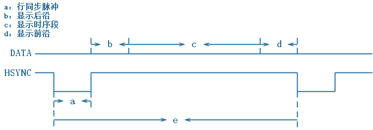 图2 行时序 |
 图3 场时序 |
vga信号中不存在点像素的频率,因此具体的工作频率需要通过分辨率和场频率计算得来。以[email protected](60Hz)为例,每场对应806个行周期,其中有768个显示行;每显示行包括1344个点时钟,其中有1024个有效显示点。故点时钟频率约为1344x806x60=64995840Hz,即约为65MHz。下面是一些常用的VGA分辨率时序参数:
| 显示模式 | a | b | c | d | e | f | g | h | i | k |
|---|---|---|---|---|---|---|---|---|---|---|
| 640x480@60Hz | 96 | 48 | 640 | 16 | 800 | 2 | 33 | 480 | 10 | 525 |
| 800x600@60Hz | 128 | 88 | 800 | 40 | 1056 | 4 | 23 | 600 | 1 | 623 |
| 1024x768@60Hz | 136 | 160 | 1024 | 24 | 1344 | 6 | 29 | 768 | 3 | 806 |
| 1280x720@60Hz | 40 | 220 | 1280 | 110 | 1650 | 5 | 20 | 720 | 5 | 750 |
| 1280x1024@60Hz | 112 | 248 | 1280 | 48 | 1688 | 3 | 38 | 1024 | 1 | 1066 |
| 1920x1080@60Hz | 44 | 148 | 1920 | 88 | 2200 | 5 | 36 | 1080 | 4 | 1125 |
注意:上表参数单位为像素,字母含义对比时序图理解(a/f为同步脉冲,b/g为显示后沿,c/h为显示时序段,d/i为显示前沿,e/k为总时序)。
3.2. 地址码线说明
该部分主要是为即插即用技术服务的。

如果支持DDC功能,那么将允许主机和显示器之间进行通信,显示器将把一系列数值信息传给主机,当显卡接收到这部分信息后,会根据显示器的参数自动进行匹配,实现即插即用。同时,还能够利用该功能对显示器的故障等方面进行检测。
关于此部分驱动的实现,我暂时还没有用FPGA实现过,也没有找到可供附上的例文,后续若有涉猎,会更新附上。若有小伙伴需要用到这方面,可以通过参考arm微处理器的显示驱动来寻找灵感,亦可使用FPGA与arm的联合开发来实现。
4. 硬件连接
红色视频信号、绿色视频信号与蓝色视频信号输入均为模拟信号,采用RS343电平标准。
一般在使用FPGA驱动VGA显示时,需要配有相应的驱动电路。现在许多FPGA开发板都配有VGA接口电阻网络,能够较好的满足VGA模拟信号的输出。具体阻抗匹配办法,可以参考VGA 接口电阻网络阻抗匹配。
5. 示例代码及上机验证
下示VGA信号的行为级建模(vhdl居然不高亮):
library ieee;
use ieee.std_logic_1164.all;
use ieee.std_logic_unsigned.all;
use ieee.std_logic_arith.all;

------------------------------------------------------------------------------------------------------------------------
-- 1024*768 60Hz VGA
------------------------------------------------------------------------------------------------------------------------
entity VGA is

    -- 参数设定
    generic(
        -- 水平扫描参数设定
        LinePeriod   : integer := 1344;     -- 行周期数
        H_SyncPulse  : integer :=  136;     -- 行同步脉冲(Sync a)
        H_BackPorch  : integer :=  160;     -- 显示后沿(Back porch b)
        H_ActivePix  : integer := 1024;     -- 显示时序段(Display interval c)
        H_FrontPorch : integer :=   24;     -- 显示前沿(Front porch d)
        Hde_start    : integer :=  296;
        Hde_end      : integer := 1320;
        H_unitlength : integer :=    1;

        -- 垂直扫描参数设定
        FramePeriod  : integer := 806;      -- 列周期数
        V_SyncPulse  : integer :=   6;      -- 列同步脉冲(Sync o)
        V_BackPorch  : integer :=  29;      -- 显示后沿(Back porch p)
        V_ActivePix  : integer := 768;      -- 显示时序段(Display interval q)
        V_FrontPorch : integer :=   3;      -- 显示前沿(Front porch r)
        Vde_start    : integer :=  35;
        Vde_end      : integer := 803;
        V_unitlength : integer :=   1
        );

	 -- 外部信号定义
    port(
    	-- 输入端口
    	rst      : in  std_logic;
    	fpga_clk : in  std_logic;

    	-- 输出端口
    	vga_hs   : out std_logic;
    	vga_vs   : out std_logic;
    	vga_r    : out std_logic_vector (4 downto 0);
    	vga_g    : out std_logic_vector (5 downto 0);
    	vga_b    : out std_logic_vector (4 downto 0)
    	);

end VGA;

architecture behavioral of VGA is

	-- 内部信号定义
    signal x_cnt        : integer range 0 to  1344;
    signal y_cnt		: integer range 0 to   806;
    signal data		    : integer range 0 to 65535;

    signal vga_r_reg	: std_logic_vector ( 4 downto 0);
    signal vga_g_reg	: std_logic_vector ( 5 downto 0);
    signal vga_b_reg	: std_logic_vector ( 4 downto 0);
	 signal data_reg  : std_logic_vector (15 downto 0);

    signal hsync_r		: std_logic;
    signal vsync_r		: std_logic;
    signal hsync_de		: std_logic;
    signal vsync_de		: std_logic;
    signal vga_clk		: std_logic;

    -- 器件声明
    component PLL
        port(
            CLK_IN1  : in  std_logic;
            CLK_OUT1 : out std_logic;
            RESET    : in  std_logic;
            LOCKED   : out std_logic
            );
    end component;

begin

    -- 内部时钟信号
    P0: PLL port map (CLK_IN1=>fpga_clk, CLK_OUT1=>vga_clk, RESET=>'0');

    -- 水平扫描计数
    process(vga_clk)
    begin
        if rising_edge(vga_clk) then
            if rst='0' then
                x_cnt <= 1;
            elsif x_cnt=LinePeriod then
                x_cnt <= 1;
            elsif rst='1' then
                x_cnt <= x_cnt+H_unitlength;
            end if;
        end if;
    end process;

    -- 垂直扫描计数
    process(vga_clk)
    begin
        if rising_edge(vga_clk) then
            if rst='0' then
                y_cnt <= 1;
            elsif y_cnt=FramePeriod then
                y_cnt <= 1;
            elsif x_cnt=LinePeriod then
                y_cnt <= y_cnt+V_unitlength;
            end if;
        end if;
    end process;

    -- 水平扫描信号
    process(vga_clk)
    begin
        if rising_edge(vga_clk) then
            if rst='0' then
                hsync_r <= '1';
            elsif x_cnt=H_unitlength then
                hsync_r <= '0';
            elsif x_cnt=H_SyncPulse then
                hsync_r <= '1';
            end if;
        end if ;
    end process;

    process(vga_clk)
    begin
        if rising_edge(vga_clk) then
            if rst='0' then
                hsync_de <= '0';
            elsif x_cnt=Hde_start then
                hsync_de <= '1';
            elsif x_cnt=Hde_end then
                hsync_de <= '0';
            end if;
        end if ;
    end process;

    -- 垂直扫描信号
    process(vga_clk)
    begin
        if rising_edge(vga_clk) then
            if rst='0' then
                vsync_r <= '1';
            elsif y_cnt=V_unitlength then
                vsync_r <= '0';
            elsif y_cnt=V_SyncPulse then
                vsync_r <= '1';
            end if;
        end if ;
    end process;

    process(vga_clk)
    begin
        if rising_edge(vga_clk) then
            if rst='0' then
                vsync_de <= '0';
            elsif y_cnt=Vde_start then
                vsync_de <= '1';
            elsif y_cnt=Vde_end then
                vsync_de <= '0';
            end if;
        end if ;
    end process;

    -- 外部连接
    with (hsync_de and vsync_de) select
    vga_r <= vga_r_reg when '1',
             "00000" when '0';

    with (hsync_de and vsync_de) select
    vga_g <= vga_g_reg when '1',
             "000000" when '0';

    with (hsync_de and vsync_de) select
    vga_b <= vga_b_reg when '1',
             "00000" when '0';

    vga_hs <= hsync_r;
    vga_vs <= vsync_r;

    -- 彩条图像
    process(vga_clk)
    begin
        if falling_edge(vga_clk) then
            if x_cnt=300 then
                data <= 16#f800#;
            elsif x_cnt=420 then
                data <= 16#07e0#;
            elsif x_cnt=540 then
                data <= 16#001f#;
            elsif x_cnt=660 then
                data <= 16#f81f#;
            elsif x_cnt=780 then
                data <= 16#ffe0#;
            elsif x_cnt=900 then
                data <= 16#07ff#;
            elsif x_cnt=1020 then
                data <= 16#ffff#;
            elsif x_cnt=1140 then
                data <= 16#fc00#;
            elsif x_cnt=1260 then
                data <= 16#0000#;
            end if;
        end if;
    end process;

    -- 图像显示
	 data_reg <= conv_std_logic_vector(data, 16);

    process(vga_clk, rst)
    begin
        if rst='0' then
            vga_r_reg <= "00000";
            vga_g_reg <= "000000";
            vga_b_reg <= "00000";
        elsif falling_edge(vga_clk) then
            vga_r_reg <= data_reg(15 downto 11);
            vga_g_reg <= data_reg(10 downto 5);
            vga_b_reg <= data_reg(4 downto 0);
        end if;
    end process;

end behavioral;
仿真结果如下:
 图4 仿真结果 |
上面那个好像也看不出来啥,下面是上机验证的结果:
 |
 |
| 图5 上机结果 | |
6. 注意事项
上示代码中,pll的rst端直接被我拉低了,我使用的实验板型号是Xilinx Spartan6的XC6SLX9,不同型号器件可能存在差异,请详细阅读IP核的数据手册。
另注意,原代码中pll的rst端被我接了其他输入信号,在ISE中调用pll时存在被锁住的情况,查其原因是:在给pll输入时钟时,rst端的输入信号存在"U"的时序,之后pll将会被一直锁住。消除该段时序后,pll正常工作。
