layout: post
tags: [STM32]
comments: true
重点内容
不管是基于标准库还是直接操作寄存器,因为TIM定时器的功能比较多,这里单纯只从定时器的角度进行学习,这里需要重点关注的地方应该有以下几点:
- 定时器时钟频率的计算;
- 计数器计数的模式,以及一般模式会有哪些应用场景;
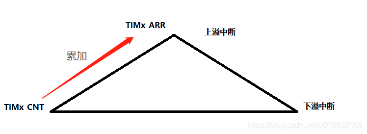
- 向上计数
- 向下计数
- 中央对齐模式:该模式下需要关注触发中断几种的方式
- 向上溢出中断;
- 向下溢出中断;
- 向上和向下都产生溢出中断;
时基单元
TIM1定时器是一个16位计数器以及相关的自动装载寄存器,比较寄存器,预分频器,可以实现向上,向下,或者向上再向下的计数模式;
基本的时基单元分为:
- 计数器寄存器(
TIMx_CNT) - 预分频器寄存器 (
TIMx_PSC) - 自动装载寄存器 (
TIMx_ARR) - 重复次数寄存器 (
TIMx_RCR)
可以参考STM32参考手册查看相关的寄存器配置说明
下面是TIM功能的整体框图,功能很多,提取了一下计数器的寄存器相应关系;

标准库中,时基单元封装到结构体TIM_TimeBaseInitTypeDef中;
源码如下;
/**
  * @brief  TIM Time Base Init structure definition
  * @note   This structure is used with all TIMx except for TIM6 and TIM7.
  */

typedef struct
{
  uint16_t TIM_Prescaler;         /*!< Specifies the prescaler value used to                                       divide the TIM clock.
                                       This parameter can be a number between 0x0000 and 0xFFFF */

  uint16_t TIM_CounterMode;       /*!< Specifies the counter mode.
                                       This parameter can be a value of @ref TIM_Counter_Mode */

  uint16_t TIM_Period;            /*!< Specifies the period value to be loaded into the active
                                       Auto-Reload Register at the next update event.
                                       This parameter must be a number between 0x0000 and 0xFFFF.  */

  uint16_t TIM_ClockDivision;     /*!< Specifies the clock division.
                                      This parameter can be a value of @ref TIM_Clock_Division_CKD */

  uint8_t TIM_RepetitionCounter;  /*!< Specifies the repetition counter value. Each time the RCR downcounter
                                       reaches zero, an update event is generated and counting restarts
                                       from the RCR value (N).
                                       This means in PWM mode that (N+1) corresponds to:
                                          - the number of PWM periods in edge-aligned mode
                                          - the number of half PWM period in center-aligned mode
                                       This parameter must be a number between 0x00 and 0xFF.
                                       @note This parameter is valid only for TIM1 and TIM8. */
} TIM_TimeBaseInitTypeDef;
基于标准库的时钟频率计算:
TIMclock = SYSclock * 1/TIM_Prescaler * TIM_Period
	/* Compute the value to be set in ARR regiter to generate signal frequency at 17.57 Khz */
	TimerPeriod = (SystemCoreClock / 17570 ) - 1;
	/* Time Base configuration */
	TIM_TimeBaseStructure.TIM_Prescaler = TIM_PSCReloadMode_Update;
	//TIM_TimeBaseStructure.TIM_CounterMode = TIM_CounterMode_Up;//
	TIM_TimeBaseStructure.TIM_CounterMode = TIM_CounterMode_CenterAligned1;
	TIM_TimeBaseStructure.TIM_Period = TimerPeriod;
	TIM_TimeBaseStructure.TIM_ClockDivision = TIM_CKD_DIV1;
	TIM_TimeBaseStructure.TIM_RepetitionCounter = 0;
	TIM_TimeBaseInit(TIM1, &TIM_TimeBaseStructure);
计数模式
- 向上计数模式
TIM_TimeBaseStructure.TIM_CounterMode = TIM_CounterMode_Up - 向下计数模式
TIM_TimeBaseStructure.TIM_CounterMode = TIM_CounterMode_Down - 中央对齐模式
TIM_TimeBaseStructure.TIM_CounterMode = TIM_CounterMode_CenterAligned1
中央对齐模式可以配置TIMx_CR1寄存器的CMS[1:0]位,从而有三种模式可以选择:
| CMS[1:0] | 选择中央对齐模式 (Center-aligned mode selection) |
|---|---|
| 00 | 边沿对齐模式。计数器依据方向位(DIR)向上或向下计数。 |
| 01 | 中央对齐模式1。计数器交替地向上和向下计数。产生下溢中断,配置为输出的通道(TIMx_CCMRx寄存器中CCxS=00)的输出比较中断标志位,只在计数器向下计数时被设置。 |
| 10 | 中央对齐模式2。计数器交替地向上和向下计数。产生上溢中断,配置为输出的通道(TIMx_CCMRx寄存器中CCxS=00)的输出比较中断标志位,只在计数器向上计数时被设置。 |
| 11 | 中央对齐模式3。计数器交替地向上和向下计数。产生下溢和上溢中断,配置为输出的通道(TIMx_CCMRx寄存器中CCxS=00)的输出比较中断标志位,在计数器向上和向下计数时均被设置。 |
具体如下图所示;
扫描二维码关注公众号,回复:
8963090 查看本文章

