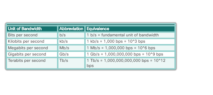
1.带宽的计量单位之间的运算
2.不同的线类型
3.
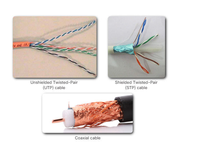
1)Unshielded Twisted-Pair Cable
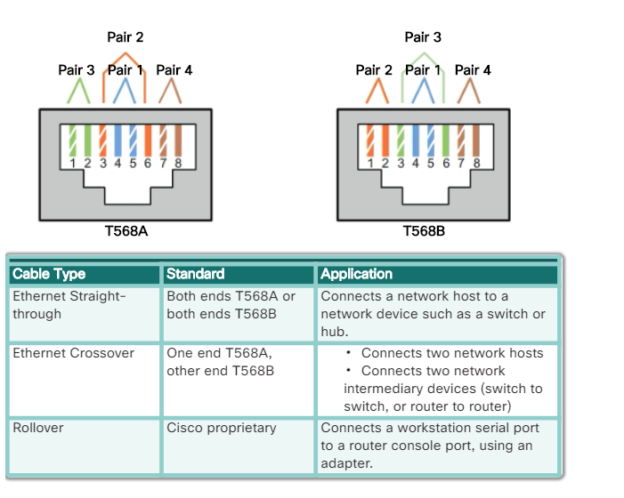
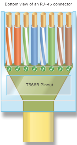
Unshielded twisted-pair (UTP) cabling is the most common networking media. UTP cabling, terminated with RJ-45 connectors, is used for interconnecting network hosts with intermediate networking devices, such as switches and routers.
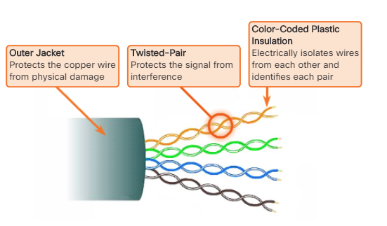
In LANs, UTP cable consists of four pairs of color-coded wires that have been twisted together and then encased in a flexible plastic sheath that protects from minor physical damage. The twisting of wires helps protect against signal interference from other wires.
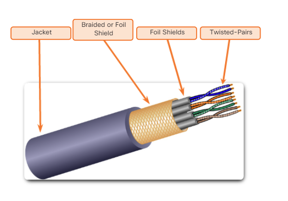
2)Shielded Twisted-Pair Cable
Shielded twisted-pair (STP) provides better noise protection than UTP cabling. However, compared to UTP cable, STP cable is significantly more expensive and difficult to install. Like UTP cable, STP uses an RJ-45 connector.
STP cables combine the techniques of shielding to counter EMI and RFI, and wire twisting to counter crosstalk. To gain the full benefit of the shielding, STP cables are terminated with special shielded STP data connectors. If the cable is improperly grounded, the shield may act as an antenna and pick up unwanted signals.
The STP cable shown uses four pairs of wires, each wrapped in a foil shield, which are then wrapped in an overall metallic braid or foil.
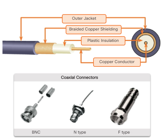
3)Coaxial Cable
Coaxial cable, or coax for short, gets its name from the fact that there are two conductors that share the same axis. As shown in the figure, coaxial cable consists of:
- A copper conductor used to transmit the electronic signals.
- A layer of flexible plastic insulation surrounding a copper conductor.
- The insulating material is surrounded in a woven copper braid, or metallic foil, that acts as the second wire in the circuit and as a shield for the inner conductor. This second layer, or shield, also reduces the amount of outside electromagnetic interference.
- The entire cable is covered with a cable jacket to prevent minor physical damage.
There are different types of connectors used with coax cable.
Although UTP cable has essentially replaced coaxial cable in modern Ethernet installations, the coaxial cable design is used in:
- Wireless installations: Coaxial cables attach antennas to wireless devices. The coaxial cable carries radio frequency (RF) energy between the antennas and the radio equipment.
- Cable Internet installations: Cable service providers provide Internet connectivity to their customers by replacing portions of the coaxial cable and supporting amplification elements with fiber-optic cable. However, the wiring inside the customer's premises is still coax cable.
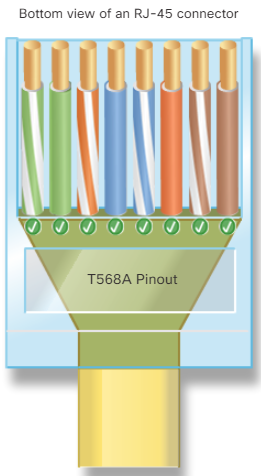
UTP cable does not use shielding to counter the effects of EMI and RFI. Instead, cable designers have discovered that they can limit the negative effect of crosstalk by:
- 1)Cancellation: Designers now pair wires in a circuit. When two wires in an electrical circuit are placed close together, their magnetic fields are the exact opposite of each other. Therefore, the two magnetic fields cancel each other and also cancel out any outside EMI and RFI signals.
- 2)Varying the number of twists per wire pair: To further enhance the cancellation effect of paired circuit wires, designers vary the number of twists of each wire pair in a cable. UTP cable must follow precise specifications governing how many twists or braids are permitted per meter (3.28 feet) of cable. Notice in the figure that the orange/orange white pair is twisted less than the blue/blue white pair. Each colored pair is twisted a different number of times.
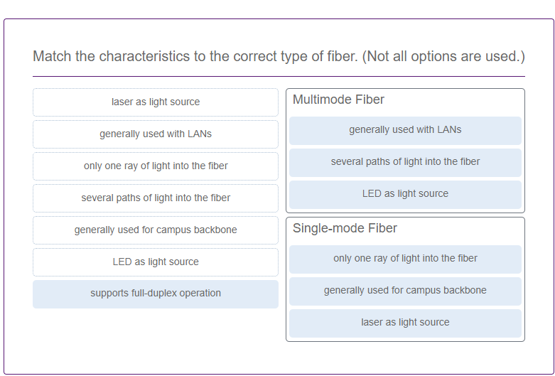
7.光纤的内部结构
http://cisco.sdut.edu.cn/old/course/IntroNet_en/#4.2.3.3
http://cisco.sdut.edu.cn/old/course/IntroNet_en/#4.2.3.4
http://cisco.sdut.edu.cn/old/course/IntroNet_en/#4.2.3.6
单模光纤的传输距离大于多模光纤
8.数据链路层的子层
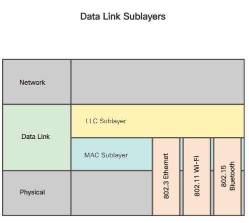
9.Logical Link Control (LLC)
Media Access Control (MAC)
10.
Contention-Based Access – CSMA/CA
Another form of CSMA that is used by IEEE 802.11 WLANs is Carrier Sense Multiple Access/Collision Avoidance (CSMA/CA). CMSA/CA uses a method similar to CSMA/CD to detect if the media is clear. CMSA/CA also uses additional techniques. CMSA/CA does not detect collisions but attempts to avoid them by waiting before transmitting. Each device that transmits includes the time duration that it needs for the transmission. All other wireless devices receive this information and know how long the medium will be unavailable, as shown in the figure. After a wireless device sends an 802.11 frame, the receiver returns an acknowledgment so that the sender knows the frame arrived.
Whether it is an Ethernet LAN using hubs, or a WLAN, contention-based systems do not scale well under heavy media use. It is important to note that Ethernet LANs using switches do not use a contention-based system because the switch and the host NIC operate in full-duplex mode.
Contention-Based Access – CSMA/CD
WLANs, Ethernet LANs with hubs, and legacy Ethernet bus networks are all examples of contention-based access networks. All of these networks operate in half-duplex mode. This requires a process to govern when a device can send and what happens when multiple devices send at the same time.
Frame Fields
Framing breaks the stream into decipherable groupings, with control information inserted in the header and trailer as values in different fields. This format gives the physical signals a structure that can be received by nodes and decoded into packets at the destination.
As shown in the figure, generic frame field types include:
- Frame start and stop indicator flags - Used to identify the beginning and end limits of the frame.
- Addressing - Indicates the source and destination nodes on the media.
- Type - Identifies the Layer 3 protocol in the data field.
- Control - Identifies special flow control services such as quality of service (QoS). QoS is used to give forwarding priority to certain types of messages. Data link frames carrying voice over IP (VoIP) packets normally receive priority because they are sensitive to delay.
- Data - Contains the frame payload (i.e., packet header, segment header, and the data).
- Error Detection - These frame fields are used for error detection and are included after the data to form the trailer.
12.
Frame Fields
Framing breaks the stream into decipherable groupings, with control information inserted in the header and trailer as values in different fields. This format gives the physical signals a structure that can be received by nodes and decoded into packets at the destination.
As shown in the figure, generic frame field types include:
- Frame start and stop indicator flags - Used to identify the beginning and end limits of the frame.
- Addressing - Indicates the source and destination nodes on the media.
- Type - Identifies the Layer 3 protocol in the data field.
- Control - Identifies special flow control services such as quality of service (QoS). QoS is used to give forwarding priority to certain types of messages. Data link frames carrying voice over IP (VoIP) packets normally receive priority because they are sensitive to delay.
- Data - Contains the frame payload (i.e., packet header, segment header, and the data).
- Error Detection - These frame fields are used for error detection and are included after the data to form the trailer.
13.
数据链路层的协议包括以下几种:
- Ethernet
- 802.11 Wireless
- Point-to-Point Protocol (PPP)
- HDLC
- Frame Relay
Frame Fields
Framing breaks the stream into decipherable groupings, with control information inserted in the header and trailer as values in different fields. This format gives the physical signals a structure that can be received by nodes and decoded into packets at the destination.
As shown in the figure, generic frame field types include:
- Frame start and stop indicator flags - Used to identify the beginning and end limits of the frame.
- Addressing - Indicates the source and destination nodes on the media.
- Type - Identifies the Layer 3 protocol in the data field.
- Control - Identifies special flow control services such as quality of service (QoS). QoS is used to give forwarding priority to certain types of messages. Data link frames carrying voice over IP (VoIP) packets normally receive priority because they are sensitive to delay.
- Data - Contains the frame payload (i.e., packet header, segment header, and the data).
- Error Detection - These frame fields are used for error detection and are included after the data to form the trailer.
Data link layer protocols include:
- Ethernet
- 802.11 Wireless
- Point-to-Point Protocol (PPP)
- HDLC
- Frame Relay
14.
Frame Fields
Framing breaks the stream into decipherable groupings, with control information inserted in the header and trailer as values in different fields. This format gives the physical signals a structure that can be received by nodes and decoded into packets at the destination.
As shown in the figure, generic frame field types include:
- Frame start and stop indicator flags - Used to identify the beginning and end limits of the frame.
- Addressing - Indicates the source and destination nodes on the media.
- Type - Identifies the Layer 3 protocol in the data field.
- Control - Identifies special flow control services such as quality of service (QoS). QoS is used to give forwarding priority to certain types of messages. Data link frames carrying voice over IP (VoIP) packets normally receive priority because they are sensitive to delay.
- Data - Contains the frame payload (i.e., packet header, segment header, and the data).
- Error Detection - These frame fields are used for error detection and are included after the data to form the trailer
15.Data link layer protocols include:
- Ethernet
- 802.11 Wireless
- Point-to-Point Protocol (PPP)
- HDLC
- Frame Relay
- 16.网络接入层
Network Access
The TCP/IP network access layer is the equivalent of the OSI data link layer (Layer 2) and the physical layer (Layer 1).
The OSI physical layer provides the means to transport the bits that make up a data link layer frame across the network media. The physical components are the electronic hardware devices, media, and other connectors that transmit and carry the signals to represent the bits. Hardware components such as network adapters (NICs), interfaces and connectors, cable materials, and cable designs are all specified in standards associated with the physical layer. The physical layer standards address three functional areas: physical components, frame encoding technique, and signaling method.
Using the proper media is an important part of network communications. Without the proper physical connection, either wired or wireless, communications between any two devices will not occur.
Wired communication consists of copper media and fiber cable:
- There are three main types of copper media used in networking: unshielded-twisted pair (UTP), shielded-twisted pair (STP), and coaxial cable. UTP cabling is the most common copper networking media.
- Optical fiber cable has become very popular for interconnecting infrastructure network devices. It permits the transmission of data over longer distances and at higher bandwidths (data rates) than any other networking media. Unlike copper wires, fiber-optic cable can transmit signals with less attenuation and is completely immune to EMI and RFI.
Wireless media carry electromagnetic signals that represent the binary digits of data communications using radio or microwave frequencies.
The number of wireless-enabled devices continues to increase. For this reason, wireless has become the medium of choice for home networks and is quickly gaining in popularity in enterprise networks.
The data link layer handles the exchange of frames between nodes over a physical network media. It allows the upper layers to access the media and controls how data is placed and received on the media.
Among the different implementations of the data link layer protocols, there are different methods of controlling access to the media. These media access control techniques define if and how the nodes share the media. The actual media access control method used depends on the topology and media sharing. LAN and WAN topologies can be physical or logical. It is the logical topology that influences the type of network framing and media access control used. WANs are commonly interconnected using the point-to-point, hub and spoke, or mesh physical topologies. In shared media LANs, end devices can be interconnected using the star, bus, ring, or extended star physical topologies.
All data link layer protocols encapsulate the Layer 3 PDU within the data field of the frame. However, the structure of the frame and the fields contained in the header and trailer vary according to the protocol.
17.