- 三层交换vlan间通信
问题
VLAN实现了广播域的隔离,同时也将VLAN间的通信隔离了。三层交换技术使得VLAN间可以通信。
1)通过三层交换实现VLAN间通信
方案
为了解决了传统路由器低速、复杂所造成的网络瓶颈问题,引入了三层交换技术。它根据实际应用时的情况,灵活地在网络第二层或者第三层进行网络分段。具有三层交换功能的设备是一个带有第三层路由功能的第二层交换机。
简单地说,三层交换技术就是:二层交换技术+三层转发技术。
三层交换实现的拓扑如图-1所示:
图-1
步骤
实现此案例需要按照如下步骤进行。
步骤一:在连接终端的PC机上划分3个VLAN,并按图-1把PC机加入相应VLAN
tarenasw-2L(config)#vlan 2 //vlan1是默认VLAN,不需创建
tarenasw-2L(config-vlan)#name HR
tarenasw-2L(config-vlan)#vlan 3
tarenasw-2L(config-vlan)#name Sales
tarenasw-2L(config-vlan)#exit
tarenasw-2L(config)#interface f0/1
tarenasw-2L(config-if)#switchport mode access
tarenasw-2L(config-if)#switchport access vlan 1
tarenasw-2L(config-if)#interface f0/2
tarenasw-2L(config-if)#switchport mode access
tarenasw-2L(config-if)#switchport access vlan 2
tarenasw-2L(config-if)#interface f0/3
tarenasw-2L(config-if)#switchport mode access
tarenasw-2L(config-if)#switchport access vlan 3
步骤二:查看划分完的VLAN信息
VLAN1是默认VLAN,不需单独创建,也不能改名。所有端口默认都在VLAN1中。
tarenasw-2L#show vlan
VLAN Name Status Ports
1 default active Fa0/1, Fa0/4, Fa0/5, Fa0/6
Fa0/7, Fa0/8, Fa0/9, Fa0/10
Fa0/11, Fa0/12, Fa0/13, Fa0/14
Fa0/15, Fa0/16, Fa0/17, Fa0/18
Fa0/19, Fa0/20, Fa0/21, Fa0/22
Fa0/23, Fa0/24, Gig1/1, Gig1/2
2 HR active Fa0/2
3 Sales active Fa0/3
步骤三:将与三层交换机连接的二层交换机Fa0/24端口设置为中继模式
tarenasw-2L(config)#interface f0/24
tarenasw-2L(config-if)#switchport mode trunk
步骤四:在三层交换机上创建与二层交换机一样的VLAN
tarenasw-3L(config)#vlan 2
tarenasw-3L(config-vlan)#name HR
tarenasw-3L(config-vlan)#vlan 3
tarenasw-3L(config-vlan)#name Sales
步骤五:将与二层交换机连接的三层交换机Fa0/24端口设置为中继模式
tarenasw-3L(config)#interface f0/24
tarenasw-3L(config-if)#switchport trunk encapsulation dot1q
tarenasw-3L(config-if)#switchport mode trunk
步骤六:在三层交换机上创建SVI端口
三层交换只要简单的把每个VLAN当成一个逻辑端口,配好IP地址并启用交换机的路由功能即可实现。
VLAN创建完成并把接口加入VLAN后,创建SVI时该SVI端口会自动处于激活状态,不用运行no shutdown命令。快速查看端口状态命令为show ip interface brief。
tarenasw-3L(config)#interface vlan 1
tarenasw-3L(config-if)#ip address 192.168.1.1 255.255.255.0
tarenasw-3L(config-if)#interface vlan 2
tarenasw-3L(config-if)#ip address 192.168.2.1 255.255.255.0
tarenasw-3L(config-if)#interface vlan 3
tarenasw-3L(config-if)#ip address 192.168.3.1 255.255.255.0
步骤七:启用三层交换机的路由功能,并查看路由表
配置三层交换并不需要配置静态路由或动态路由协议,因为所有的端口都是直连端口。
tarenasw-3L(config)#ip routing
tarenasw-3L(config)#exit
tarenasw-3L#show ip route
Codes: C - connected, S - static, I - IGRP, R - RIP, M - mobile, B - BGP
D - EIGRP, EX - EIGRP external, O - OSPF, IA - OSPF inter area
N1 - OSPF NSSA external type 1, N2 - OSPF NSSA external type 2
E1 - OSPF external type 1, E2 - OSPF external type 2, E - EGP
i - IS-IS, L1 - IS-IS level-1, L2 - IS-IS level-2, ia - IS-IS inter area
* - candidate default, U - per-user static route, o - ODR
P - periodic downloaded static route
Gateway of last resort is not set
C 192.168.1.0/24 is directly connected, Vlan1
C 192.168.2.0/24 is directly connected, Vlan2
C 192.168.3.0/24 is directly connected, Vlan3
步骤八:在PC1机上测试VLAN间的连通性
PC>ipconfig
FastEthernet0 Connection:(default port)
Link-local IPv6 Address…: FE80::2D0:D3FF:FE2E:5D25
IP Address…: 192.168.1.10
Subnet Mask…: 255.255.255.0
Default Gateway…: 192.168.1.1
PC>ping 192.168.2.10
Pinging 192.168.2.10 with 32 bytes of data:
Request timed out.
Reply from 192.168.2.10: bytes=32 time=0ms TTL=127
Reply from 192.168.2.10: bytes=32 time=0ms TTL=127
Reply from 192.168.2.10: bytes=32 time=0ms TTL=127
Ping statistics for 192.168.2.10:
Packets: Sent = 4, Received = 3, Lost = 1 (25% loss),
Approximate round trip times in milli-seconds:
Minimum = 0ms, Maximum = 0ms, Average = 0ms
PC>ping 192.168.3.10
Pinging 192.168.3.10 with 32 bytes of data:
Request timed out.
Reply from 192.168.3.10: bytes=32 time=0ms TTL=127
Reply from 192.168.3.10: bytes=32 time=0ms TTL=127
Reply from 192.168.3.10: bytes=32 time=0ms TTL=127
Ping statistics for 192.168.3.10:
Packets: Sent = 4, Received = 3, Lost = 1 (25% loss),
Approximate round trip times in milli-seconds:
Minimum = 0ms, Maximum = 0ms, Average = 0ms
PC>
2. 三层交换配置路由
问题
三层交换机实现了VLAN间互通后,还要与其他网络进行通信,这样就需要有相关的路由机制。
1)交换接口配置为三层接口实现路由间通信
方案
三层交换机既然具有三层功能,也就可以实现与路由器相似的配置。既可以把交换接口配置为三层接口,也可以在其上配置静态、动态路由。通过对三层交换机的路由配置,实现VLAN与其他网络的互通。
网络的拓扑结构如图-2所示:
图-2
步骤
实现此案例需要按照如下步骤进行。
步骤一:VLAN等配置与上面2 三层交换vlan间通信通完全一致,不再赘述
步骤二:将三层交换的Fa0/23口配置为三层路由端口,并配置IP地址
三层交换机的物理端口默认是二层端口,只具有二层特性,不能配置IP地址。把二层端口配置为三层端口后,该端口就具备路由功能了,可以配置IP地址,但同时也就关闭了其二层特性,比如不能把三层端口加入VLAN。
二层端口(交换机上的端口默认都是二层端口)默认是激活状态,那些没有使用到的端口为了安全应该手工将其禁用(shutdown);而三层端口(路由器上的端口或是三层交换机上被配置成路由端口的端口)默认是禁用状态,在使用之前务必要将其激活(no shutdown)。
tarenasw-3L(config)#interface f0/23
tarenasw-3L(config-if)#no switchport
tarenasw-3L(config-if)#ip address 192.168.10.2 255.255.255.0
tarenasw-3L(config-if)#no shutdown
步骤三:配置路由器的端口IP地址
tarena-rouer(config)#interface f0/0
tarena-rouer(config-if)#ip address 192.168.10.1 255.255.255.0
tarena-rouer(config-if)#no shutdown
tarena-rouer(config-if)#interface f0/1
tarena-rouer(config-if)#ip address 200.1.1.1 255.255.255.0
tarena-rouer(config-if)#no shutdown
步骤四:在三层交换机上配置默认路由,以便VLAN内主机可以与外界网络互联
tarenasw-3L(config)#ip route 0.0.0.0 0.0.0.0 192.168.10.1
tarenasw-3L(config)#exit
tarenasw-3L#show ip route
Codes: C - connected, S - static, I - IGRP, R - RIP, M - mobile, B - BGP
D - EIGRP, EX - EIGRP external, O - OSPF, IA - OSPF inter area
N1 - OSPF NSSA external type 1, N2 - OSPF NSSA external type 2
E1 - OSPF external type 1, E2 - OSPF external type 2, E - EGP
i - IS-IS, L1 - IS-IS level-1, L2 - IS-IS level-2, ia - IS-IS inter area
* - candidate default, U - per-user static route, o - ODR
P - periodic downloaded static route
Gateway of last resort is 192.168.10.1 to network 0.0.0.0
C 192.168.1.0/24 is directly connected, Vlan1
C 192.168.2.0/24 is directly connected, Vlan2
C 192.168.3.0/24 is directly connected, Vlan3
C 192.168.10.0/24 is directly connected, FastEthernet0/23
S* 0.0.0.0/0 [1/0] via 192.168.10.1
步骤五:在路由器上配置到达三个VLAN网络的静路由
tarena-rouer(config)#ip route 192.168.1.0 255.255.255.0 192.168.10.2
tarena-rouer(config)#ip route 192.168.2.0 255.255.255.0 192.168.10.2
tarena-rouer(config)#ip route 192.168.3.0 255.255.255.0 192.168.10.2
tarena-rouer(config)#exit
tarena-rouer#show ip route
Codes: C - connected, S - static, I - IGRP, R - RIP, M - mobile, B - BGP
D - EIGRP, EX - EIGRP external, O - OSPF, IA - OSPF inter area
N1 - OSPF NSSA external type 1, N2 - OSPF NSSA external type 2
E1 - OSPF external type 1, E2 - OSPF external type 2, E - EGP
i - IS-IS, L1 - IS-IS level-1, L2 - IS-IS level-2, ia - IS-IS inter area
* - candidate default, U - per-user static route, o - ODR
P - periodic downloaded static route
Gateway of last resort is not set
S 192.168.1.0/24 [1/0] via 192.168.10.2
S 192.168.2.0/24 [1/0] via 192.168.10.2
S 192.168.3.0/24 [1/0] via 192.168.10.2
C 192.168.10.0/24 is directly connected, FastEthernet0/0
C 200.1.1.0/24 is directly connected, FastEthernet0/1
tarena-rouer#
步骤六:在Server上测试与三个VLAN的连通性
SERVER>ipconfig
FastEthernet0 Connection:(default port)
Link-local IPv6 Address…: FE80::2E0:8FFF:FE14:BB43
IP Address…: 200.1.1.10
Subnet Mask…: 255.255.255.0
Default Gateway…: 200.1.1.1
SERVER>ping 192.168.1.10
Pinging 192.168.1.10 with 32 bytes of data:
Request timed out.
Reply from 192.168.1.10: bytes=32 time=0ms TTL=126
Reply from 192.168.1.10: bytes=32 time=0ms TTL=126
Reply from 192.168.1.10: bytes=32 time=1ms TTL=126
Ping statistics for 192.168.1.10:
Packets: Sent = 4, Received = 3, Lost = 1 (25% loss),
Approximate round trip times in milli-seconds:
Minimum = 0ms, Maximum = 1ms, Average = 0ms
SERVER>ping 192.168.2.10
Pinging 192.168.2.10 with 32 bytes of data:
Reply from 192.168.2.10: bytes=32 time=0ms TTL=126
Reply from 192.168.2.10: bytes=32 time=0ms TTL=126
Reply from 192.168.2.10: bytes=32 time=0ms TTL=126
Reply from 192.168.2.10: bytes=32 time=0ms TTL=126
Ping statistics for 192.168.2.10:
Packets: Sent = 4, Received = 4, Lost = 0 (0% loss),
Approximate round trip times in milli-seconds:
Minimum = 0ms, Maximum = 0ms, Average = 0ms
SERVER>ping 192.168.3.10
Pinging 192.168.3.10 with 32 bytes of data:
Reply from 192.168.3.10: bytes=32 time=1ms TTL=126
Reply from 192.168.3.10: bytes=32 time=0ms TTL=126
Reply from 192.168.3.10: bytes=32 time=0ms TTL=126
Reply from 192.168.3.10: bytes=32 time=0ms TTL=126
Ping statistics for 192.168.3.10:
Packets: Sent = 4, Received = 4, Lost = 0 (0% loss),
Approximate round trip times in milli-seconds:
Minimum = 0ms, Maximum = 1ms, Average = 0ms
SERVER>
3. RIP动态路由配置
问题
在相对较小而且结构不变的网络中,静态路由是很好的解决方案,它配置简单而且不过多消耗设备资源(动态路由协议在运行时要消耗路由器内部资源,在与其他路由器更新信息时又会消耗网络资源)。
然而在大型网络中,网络非常多,而且很有可能因为某些因素的影响,网络拓扑会有轻微变化。这时如果仍然采用静态路由就非常不方便了。
1)通过RIP实现路由间通信
方案
动态路由协议配置灵活,路由器会发送自身的路由信息给其他路由器,同时也会接收其他路由器发来的路由信息建立自己的路由表。这样在路由器上就不必像静态路由那样为每个目标地址都配置路由,因为路由器可以通过协议学习这些路由。网络拓扑改变,路由信息也会自动更新,无需管理员干预。
网络拓扑如图-3所示:
图-3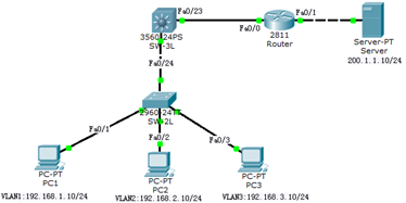
步骤
实现此案例需要按照如下步骤进行。
步骤一:VLAN以及端口配置与上面3三层交换配置路由完全一致,不再赘述配置
步骤二:将上面【1.3在三层交换机上配置路由】中的静态、默认路由删除
tarenasw-3L(config)#no ip route 0.0.0.0 0.0.0.0 192.168.10.1
tarena-rouer(config)#no ip route 192.168.1.0 255.255.255.0 192.168.10.2
tarena-rouer(config)#no ip route 192.168.2.0 255.255.255.0 192.168.10.2
tarena-rouer(config)#no ip route 192.168.3.0 255.255.255.0 192.168.10.2
步骤三:分别在三层交换机和路由器上配置RIP路由协议
RIP路由协议在配置network时,只需要配置该路由器所直连的主类网络,不与该路由器直连的网络不需要包含在network中。
RIP默认工作在第一版本下,但是RIP-V1是有类路由协议,而且通过广播的方式进行路由更新,无论是功能上还是效率上都有一些缺陷,这些缺陷RIP-V2可以弥补。在使用时建议采用RIP-V2而不是RIP-V1。
tarenasw-3L(config)#router rip
tarenasw-3L(config-router)#version 2
tarenasw-3L(config-router)#no auto-summary
tarenasw-3L(config-router)#network 192.168.1.0
tarenasw-3L(config-router)#network 192.168.2.0
tarenasw-3L(config-router)#network 192.168.3.0
tarenasw-3L(config-router)#network 192.168.10.0
tarena-rouer(config)#router rip
tarena-rouer(config-router)#version 2
tarena-rouer(config-router)#network 192.168.10.0
tarena-rouer(config-router)#network 200.1.1.0
步骤四:分别在三层交换机和路由器上查看路由表
注意以R开头的路由,这些路由表示通过RIP协议从其他运行RIP的路由器学习过来的路由。每条路由都写明了目标网络、下一跳IP地址以及从自己哪个端口发出去。
tarenasw-3L#show ip route
Codes: C - connected, S - static, I - IGRP, R - RIP, M - mobile, B - BGP
D - EIGRP, EX - EIGRP external, O - OSPF, IA - OSPF inter area
N1 - OSPF NSSA external type 1, N2 - OSPF NSSA external type 2
E1 - OSPF external type 1, E2 - OSPF external type 2, E - EGP
i - IS-IS, L1 - IS-IS level-1, L2 - IS-IS level-2, ia - IS-IS inter area
* - candidate default, U - per-user static route, o - ODR
P - periodic downloaded static route
Gateway of last resort is not set
C 192.168.1.0/24 is directly connected, Vlan1
C 192.168.2.0/24 is directly connected, Vlan2
C 192.168.3.0/24 is directly connected, Vlan3
C 192.168.10.0/24 is directly connected, FastEthernet0/23
R 200.1.1.0/24 [120/1] via 192.168.10.1, 00:00:07, FastEthernet0/23
tarena-rouer#show ip route
Codes: C - connected, S - static, I - IGRP, R - RIP, M - mobile, B - BGP
D - EIGRP, EX - EIGRP external, O - OSPF, IA - OSPF inter area
N1 - OSPF NSSA external type 1, N2 - OSPF NSSA external type 2
E1 - OSPF external type 1, E2 - OSPF external type 2, E - EGP
i - IS-IS, L1 - IS-IS level-1, L2 - IS-IS level-2, ia - IS-IS inter area
* - candidate default, U - per-user static route, o - ODR
P - periodic downloaded static route
Gateway of last resort is not set
R 192.168.1.0/24 [120/1] via 192.168.10.2, 00:00:10, FastEthernet0/0
R 192.168.2.0/24 [120/1] via 192.168.10.2, 00:00:10, FastEthernet0/0
R 192.168.3.0/24 [120/1] via 192.168.10.2, 00:00:10, FastEthernet0/0
C 192.168.10.0/24 is directly connected, FastEthernet0/0
C 200.1.1.0/24 is directly connected, FastEthernet0/1
步骤五:在Server上测试到三个VLAN中主机的通信
SERVER>ipconfig
FastEthernet0 Connection:(default port)
Link-local IPv6 Address…: FE80::2E0:8FFF:FE14:BB43
IP Address…: 200.1.1.10
Subnet Mask…: 255.255.255.0
Default Gateway…: 200.1.1.1
SERVER>ping 192.168.1.10
Pinging 192.168.1.10 with 32 bytes of data:
Reply from 192.168.1.10: bytes=32 time=0ms TTL=126
Reply from 192.168.1.10: bytes=32 time=0ms TTL=126
Reply from 192.168.1.10: bytes=32 time=0ms TTL=126
Reply from 192.168.1.10: bytes=32 time=1ms TTL=126
Ping statistics for 192.168.1.10:
Packets: Sent = 4, Received = 3, Lost = 1 (25% loss),
Approximate round trip times in milli-seconds:
Minimum = 0ms, Maximum = 1ms, Average = 0ms
SERVER>ping 192.168.2.10
Pinging 192.168.2.10 with 32 bytes of data:
Reply from 192.168.2.10: bytes=32 time=0ms TTL=126
Reply from 192.168.2.10: bytes=32 time=0ms TTL=126
Reply from 192.168.2.10: bytes=32 time=0ms TTL=126
Reply from 192.168.2.10: bytes=32 time=0ms TTL=126
Ping statistics for 192.168.2.10:
Packets: Sent = 4, Received = 4, Lost = 0 (0% loss),
Approximate round trip times in milli-seconds:
Minimum = 0ms, Maximum = 0ms, Average = 0ms
SERVER>ping 192.168.3.10
Pinging 192.168.3.10 with 32 bytes of data:
Reply from 192.168.3.10: bytes=32 time=1ms TTL=126
Reply from 192.168.3.10: bytes=32 time=0ms TTL=126
Reply from 192.168.3.10: bytes=32 time=0ms TTL=126
Reply from 192.168.3.10: bytes=32 time=0ms TTL=126
Ping statistics for 192.168.3.10:
Packets: Sent = 4, Received = 4, Lost = 0 (0% loss),
Approximate round trip times in milli-seconds:
Minimum = 0ms, Maximum = 1ms, Average = 0ms
SERVER>
31% /misc/nfsdir