在startup文件中,调用了2个函数,一个是System_Init, 另一个是main。
System_Init()在system_stm32f10x.c 这个文件中,先看一下时钟树,再分析一下这个文件。
上树:
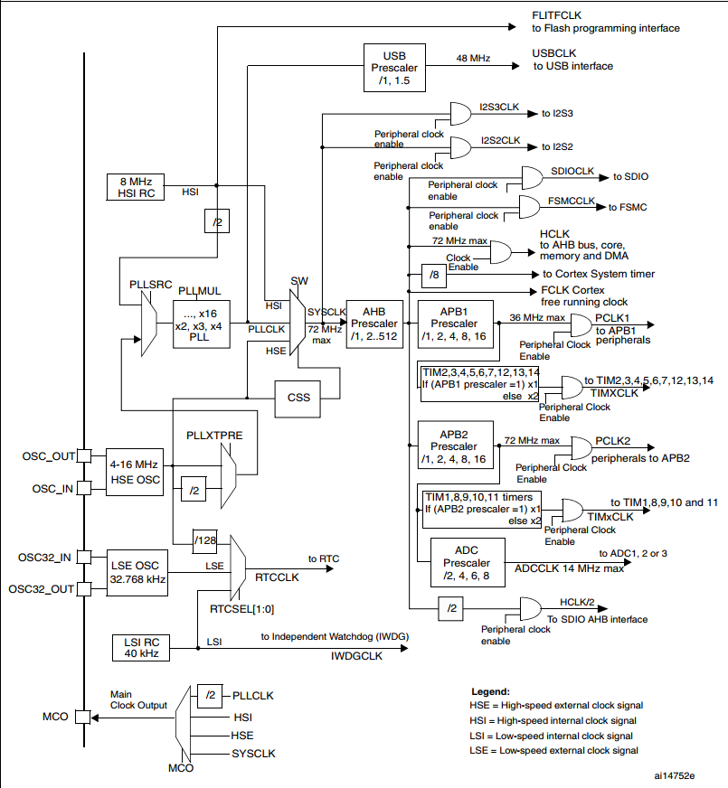
首先:时钟源有4个:
| OSC_IN / OSC_OUT | HSE | 外部高速时钟 | 一般是8MHz |
|---|---|---|---|
| OSC32_IN / OSC32_OUT | LSE | 外部低速系统时钟 | 32.768kHz |
| HSI | 内部高速时钟 | 8MHz | |
| LSI | 内部低速时钟 |
主时钟是HSE,一般为8MHz输入,在图中找到外部的该时钟输入,用这里进入时钟树的分配,
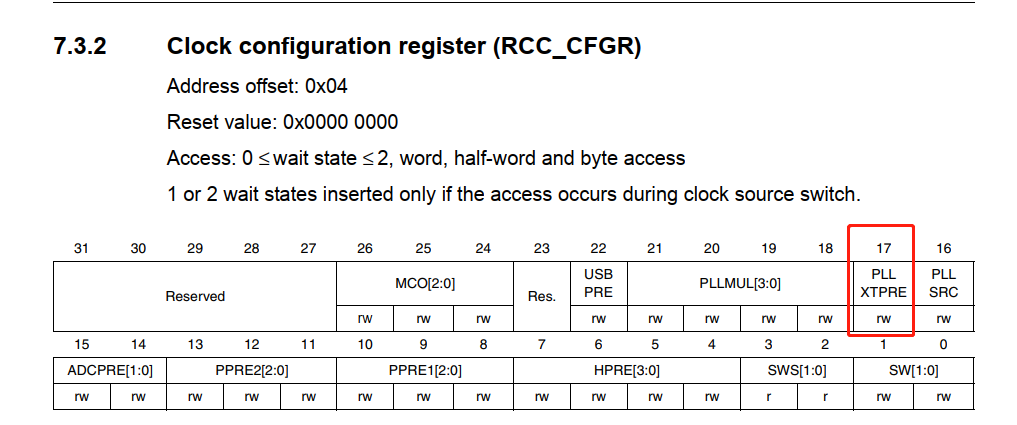
一开始就遇到2条路,
    -- 直接到达PLLXTPRE控制器 8MHz
    -- 2分频后到达 PLLXTPRE 4MHZ
一般选择不分频,4MHz太小,后面会补充说明。
PLLXTPRE是一个寄存器,控制是否2分频。
扫描二维码关注公众号,回复:
5960109 查看本文章

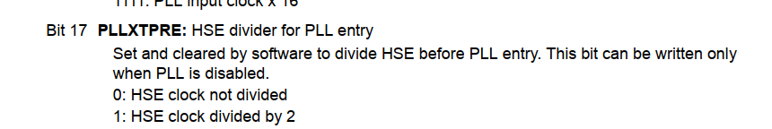
只有PLL还没使能的时候才能配置该寄存器
继续往下走:
来到PLLSRC 意味选择PLL时钟来源,
    --HSE 8M
    --HSL 必须经过2分频 4M
配置为HSE,如果HES时钟没能起来,就会被迫切换成HSL时钟,4MHz

然后PLLMUL PLL锁相环倍频,有2~16多种选择,

因为stm32最高稳定时钟是72MHz,所以如果是HSE8MHz的话,这里就可以配置成9倍频,当然可以选择更高的,只是那样系统时钟不稳定。

假设之前HSE选择2分频,4MHz,这里就算选择16倍频也只有64MHz,比72MHz低,这就为为什么不选择2分频的原因。
同样,HSI时钟必须2分频,最高也只有64MHz,比72MHz慢,且受温漂影响。

接下来是选定一种频率作为系统时钟。有3种来源
    --HSI 8MHz                  (x)
    --PLLCLK (HSE*9=72MHz)     (y)
    --LSE 32.768kHz         (x)
以PLLCLK72MHz作为系统时钟,分出3条时钟总线
--AHB    72MHz 高速
--APB2    72MHz 高速
--APB1    36MHz 慢速
包括其他的时钟也是用这种方法结合文档慢慢分析,以后遇到了再回来查阅手册。
首先找到system_init这个函数
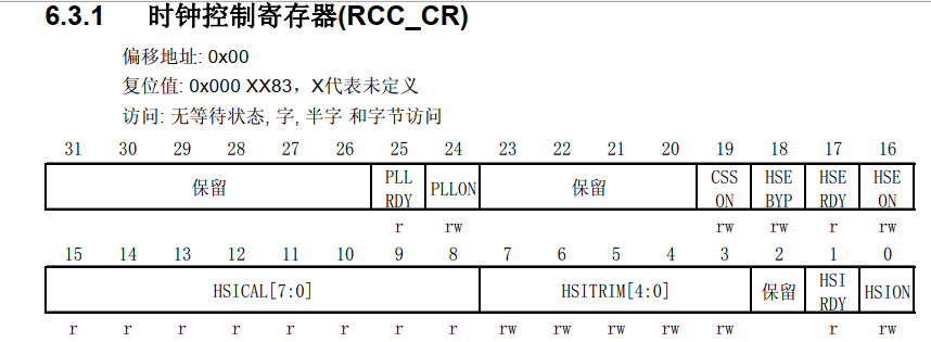
//1,使能RCC_CR
void SystemInit (void)
{
  /* Reset the RCC clock configuration to the default reset state(for debug purpose) */
  /* Set HSION bit */
  RCC->CR |= (uint32_t)0x00000001;

  /* Reset SW, HPRE, PPRE1, PPRE2, ADCPRE and MCO bits */
  RCC->CFGR &= (uint32_t)0xF0FF0000;

  /* Reset HSEON, CSSON and PLLON bits */
  RCC->CR &= (uint32_t)0xFEF6FFFF;

  /* Reset HSEBYP bit */
  RCC->CR &= (uint32_t)0xFFFBFFFF;

  /* Reset PLLSRC, PLLXTPRE, PLLMUL and USBPRE/OTGFSPRE bits */
  RCC->CFGR &= (uint32_t)0xFF80FFFF;

  /* Disable all interrupts and clear pending bits  */
  RCC->CIR = 0x009F0000;

  /* 以上,各种 reset,以下,开始配置时钟 */
  /* 跳转到SetSysClock() */
  /* Configure the System clock frequency, HCLK, PCLK2 and PCLK1 prescalers */
  /* Configure the Flash Latency cycles and enable prefetch buffer */
  SetSysClock();
  SCB->VTOR = FLASH_BASE | VECT_TAB_OFFSET; /* Vector Table Relocation in Internal FLASH. */
}
/* 根据各种宏定义决定配置成什么样的系统时钟,在之前 */
static void SetSysClock(void)
{
#ifdef SYSCLK_FREQ_HSE
  SetSysClockToHSE();
#elif defined SYSCLK_FREQ_24MHz
  SetSysClockTo24();
#elif defined SYSCLK_FREQ_36MHz
  SetSysClockTo36();
#elif defined SYSCLK_FREQ_48MHz
  SetSysClockTo48();
#elif defined SYSCLK_FREQ_56MHz
  SetSysClockTo56();
#elif defined SYSCLK_FREQ_72MHz
  SetSysClockTo72();
#endif

 /* If none of the define above is enabled, the HSI is used as System clock
    source (default after reset) */
}
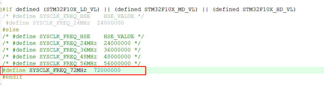
在之前就已经定义好了配置为72MHz的宏,所以进入 SetSysClockTo72();
static void SetSysClockTo72(void)
{
  __IO uint32_t StartUpCounter = 0, HSEStatus = 0;
  /* 这里是整个配置的重点函数 */
  /* SYSCLK, HCLK, PCLK2 and PCLK1 configuration ---------------------------*/
  /* Enable HSE 先使能HSE时钟*/
  RCC->CR |= ((uint32_t)RCC_CR_HSEON);

  /* Wait till HSE is ready and if Time out is reached exit  要等待HSE时钟准备好后,跳出while循环,这里有超时机制 */
  do
  {
    HSEStatus = RCC->CR & RCC_CR_HSERDY;
    StartUpCounter++;
  } while((HSEStatus == 0) && (StartUpCounter != HSE_STARTUP_TIMEOUT));

  if ((RCC->CR & RCC_CR_HSERDY) != RESET)
  {
    HSEStatus = (uint32_t)0x01;
  }
  else
  {
    HSEStatus = (uint32_t)0x00;
  }

    /* 如果HSE起来后,这里要配置2个flash预取指令相关 */
  if (HSEStatus == (uint32_t)0x01)
  {
    /* Enable Prefetch Buffer 允许预读指令 */
    FLASH->ACR |= FLASH_ACR_PRFTBE;

    /* Flash 2 wait state 预读指令间隔2个时间周期 */
    FLASH->ACR &= (uint32_t)((uint32_t)~FLASH_ACR_LATENCY);
    FLASH->ACR |= (uint32_t)FLASH_ACR_LATENCY_2;


    /* HCLK = SYSCLK 配置PLLCLK为系统时钟*/
    RCC->CFGR |= (uint32_t)RCC_CFGR_HPRE_DIV1;

    /* PCLK2 = HCLK 配置APB2时钟*/
    RCC->CFGR |= (uint32_t)RCC_CFGR_PPRE2_DIV1;

    /* PCLK1 = HCLK 配置APB1时钟*/
    RCC->CFGR |= (uint32_t)RCC_CFGR_PPRE1_DIV2;

    /*  PLL configuration: PLLCLK = HSE * 9 = 72 MHz PLL9倍频*/
    RCC->CFGR &= (uint32_t)((uint32_t)~(RCC_CFGR_PLLSRC | RCC_CFGR_PLLXTPRE |
                                        RCC_CFGR_PLLMULL));
    RCC->CFGR |= (uint32_t)(RCC_CFGR_PLLSRC_HSE | RCC_CFGR_PLLMULL9);

    /* Enable PLL 使能PLL,注意,PLL未使能的情况下才能配置之前的参数。*/
    RCC->CR |= RCC_CR_PLLON;

    /* Wait till PLL is ready 等待PLL准备好*/
    while((RCC->CR & RCC_CR_PLLRDY) == 0)
    {
    }

    /* Select PLL as system clock source 选择PLL作为系统时钟*/
    RCC->CFGR &= (uint32_t)((uint32_t)~(RCC_CFGR_SW));
    RCC->CFGR |= (uint32_t)RCC_CFGR_SW_PLL;

    /* Wait till PLL is used as system clock source 等待PLL作为系统时钟准备完毕 */
    while ((RCC->CFGR & (uint32_t)RCC_CFGR_SWS) != (uint32_t)0x08)
    {
    }
  }
  else
  { /* If HSE fails to start-up, the application will have wrong clock
         configuration. User can add here some code to deal with this error 这里交给用户自己变成,如果HSE时钟没有成功,就会进入这里 */
  }
}
#endif
顺便读一下RCC库函数
RCC库函数。
/* 函数库 按F12 跳转到函数体,就可以学习怎么使用 */
/** @defgroup RCC_Exported_Functions
  * @{
  */

void RCC_DeInit(void);    /* 重新初始化时钟配置,在自定义时钟时使用 */
void RCC_HSEConfig(uint32_t RCC_HSE);    //配置HSE时钟
ErrorStatus RCC_WaitForHSEStartUp(void); /* 等待HSE时钟准备完成 */
void RCC_AdjustHSICalibrationValue(uint8_t HSICalibrationValue);
void RCC_HSICmd(FunctionalState NewState);
void RCC_PLLConfig(uint32_t RCC_PLLSource, uint32_t RCC_PLLMul); /* PLL锁相环控制器 */
void RCC_PLLCmd(FunctionalState NewState); /* PLL 使能 */

void RCC_SYSCLKConfig(uint32_t RCC_SYSCLKSource);/* 配置系统时钟来源 1/3 */
uint8_t RCC_GetSYSCLKSource(void);
void RCC_HCLKConfig(uint32_t RCC_SYSCLK);
void RCC_PCLK1Config(uint32_t RCC_HCLK);
void RCC_PCLK2Config(uint32_t RCC_HCLK);
void RCC_ITConfig(uint8_t RCC_IT, FunctionalState NewState);

void RCC_OTGFSCLKConfig(uint32_t RCC_OTGFSCLKSource);

void RCC_ADCCLKConfig(uint32_t RCC_PCLK2);

void RCC_LSEConfig(uint8_t RCC_LSE);
void RCC_LSICmd(FunctionalState NewState);
void RCC_RTCCLKConfig(uint32_t RCC_RTCCLKSource);
void RCC_RTCCLKCmd(FunctionalState NewState);
void RCC_GetClocksFreq(RCC_ClocksTypeDef* RCC_Clocks);
void RCC_AHBPeriphClockCmd(uint32_t RCC_AHBPeriph, FunctionalState NewState);
void RCC_APB2PeriphClockCmd(uint32_t RCC_APB2Periph, FunctionalState NewState);
void RCC_APB1PeriphClockCmd(uint32_t RCC_APB1Periph, FunctionalState NewState);

void RCC_APB2PeriphResetCmd(uint32_t RCC_APB2Periph, FunctionalState NewState);
void RCC_APB1PeriphResetCmd(uint32_t RCC_APB1Periph, FunctionalState NewState);
void RCC_BackupResetCmd(FunctionalState NewState);
void RCC_ClockSecuritySystemCmd(FunctionalState NewState);
void RCC_MCOConfig(uint8_t RCC_MCO);
FlagStatus RCC_GetFlagStatus(uint8_t RCC_FLAG);
void RCC_ClearFlag(void);
ITStatus RCC_GetITStatus(uint8_t RCC_IT);
void RCC_ClearITPendingBit(uint8_t RCC_IT);
实际例子://实现超频到16倍频
#include "myclk.h"

/**
  * 1.学习系统时钟配置过程
  * 2.超频一下看会是什么情况
  * 3.MCO输出时钟
  */

void HSE_SetSystem(uint32_t RCC_PLLMul)
{
    ErrorStatus HSEStatus;

    /* 要先将已有的时钟初始化 */
    RCC_DeInit();

    /* HSE时钟使能 */
    RCC_HSEConfig(RCC_HSE_ON);

    /* 等待HSE时钟准备好 */
    HSEStatus = RCC_WaitForHSEStartUp();
    if( HSEStatus == SUCCESS )    /* HSE 时钟准备好了 */
    {
        /* HSE success*/
        /* Flash 预取值 */
        FLASH_PrefetchBufferCmd(FLASH_PrefetchBuffer_Enable);

        /* Flash 等待周期 */
        FLASH_SetLatency(FLASH_Latency_2);

        /* 配置3条时钟总线 */
        RCC_HCLKConfig(RCC_SYSCLK_Div1);
        RCC_PCLK1Config(RCC_HCLK_Div1);
        RCC_PCLK2Config(RCC_HCLK_Div2);

        /* PLL倍频 倍频数放在参数传进来*/
        RCC_PLLConfig(RCC_PLLSource_HSE_Div1,RCC_PLLMul);
        RCC_PLLCmd(ENABLE);

        /* 等待PLL 使能成功 */
        while(RCC_GetFlagStatus(RCC_FLAG_PLLRDY) == RESET);

        RCC_SYSCLKConfig(RCC_SYSCLKSource_PLLCLK);

        while(RCC_GetSYSCLKSource() != 0x08);


    }else   /* HSE 时钟未能初始化 */
    {
        /* 错误处理 */
    }
}

/* MCO 是GPIOA 8的复用输出功能 */
void MCO_GPIO_Config(void)
{
    GPIO_InitTypeDef GPIO_InitStruct;

    RCC_APB2PeriphClockCmd(MCO_GPIO_CLK,ENABLE);

    GPIO_InitStruct.GPIO_Pin = MCO_GPIO_PIN;
    GPIO_InitStruct.GPIO_Mode = GPIO_Mode_AF_PP;
    GPIO_InitStruct.GPIO_Speed = GPIO_Speed_50MHz;

    GPIO_Init(MCO_GPIO_PORT,&GPIO_InitStruct);
}
/** ****************************************************************************** * @file system_stm32f10x.c * @author MCD Application Team * @version V3.5.0 * @date 11-March-2011 * @brief CMSIS Cortex-M3 Device Peripheral Access Layer System Source File. * * 1. This file provides two functions and one global variable to be called from * user application: 这个文件提供2个函数 和 1个全局变量 以供用户调用。 * - SystemInit(): Setups the system clock (System clock source, PLL Multiplier * factors, AHB/APBx prescalers and Flash settings). * This function is called at startup just after reset and * before branch to main program. This call is made inside * the "startup_stm32f10x_xx.s" file. // 设置系统时钟,分配系统时钟,PLL锁相环,AHB/APB1和APB2的时钟和flsah的预取指令的设置,这个函数在 系统复位后,main函数被调用前执行,被启动文件所调用。 * * - SystemCoreClock variable: Contains the core clock (HCLK), it can be used * by the user application to setup the SysTick * timer or configure other parameters. * //systemCoreClock 包含了HCLK,这个变量可以被用于配置SysTick 或其他 变量配置。 * - SystemCoreClockUpdate(): Updates the variable SystemCoreClock and must * be called whenever the core clock is changed * during program execution. * // * 2. After each device reset the HSI (8 MHz) is used as system clock source. * Then SystemInit() function is called, in "startup_stm32f10x_xx.s" file, to * configure the system clock before to branch to main program. * * 3. If the system clock source selected by user fails to startup, the SystemInit() * function will do nothing and HSI still used as system clock source. User can * add some code to deal with this issue inside the SetSysClock() function. * * 4. The default value of HSE crystal is set to 8 MHz (or 25 MHz, depedning on * the product used), refer to "HSE_VALUE" define in "stm32f10x.h" file. * When HSE is used as system clock source, directly or through PLL, and you * are using different crystal you have to adapt the HSE value to your own * configuration. * ****************************************************************************** * @attention * * THE PRESENT FIRMWARE WHICH IS FOR GUIDANCE ONLY AIMS AT PROVIDING CUSTOMERS * WITH CODING INFORMATION REGARDING THEIR PRODUCTS IN ORDER FOR THEM TO SAVE * TIME. AS A RESULT, STMICROELECTRONICS SHALL NOT BE HELD LIABLE FOR ANY * DIRECT, INDIRECT OR CONSEQUENTIAL DAMAGES WITH RESPECT TO ANY CLAIMS ARISING * FROM THE CONTENT OF SUCH FIRMWARE AND/OR THE USE MADE BY CUSTOMERS OF THE * CODING INFORMATION CONTAINED HEREIN IN CONNECTION WITH THEIR PRODUCTS. * * <h2><center>© COPYRIGHT 2011 STMicroelectronics</center></h2> ****************************************************************************** */ /** @addtogroup CMSIS * @{ */ /** @addtogroup stm32f10x_system * @{ */ /** @addtogroup STM32F10x_System_Private_Includes * @{ */ #include "stm32f10x.h" /** * @} */ /** @addtogroup STM32F10x_System_Private_TypesDefinitions * @{ */ /** * @} */ /** @addtogroup STM32F10x_System_Private_Defines * @{ */ /*!< Uncomment the line corresponding to the desired System clock (SYSCLK) frequency (after reset the HSI is used as SYSCLK source) IMPORTANT NOTE: ============== 1. After each device reset the HSI is used as System clock source. 2. Please make sure that the selected System clock doesn't exceed your device's maximum frequency. 3. If none of the define below is enabled, the HSI is used as System clock source. 4. The System clock configuration functions provided within this file assume that: - For Low, Medium and High density Value line devices an external 8MHz crystal is used to drive the System clock. - For Low, Medium and High density devices an external 8MHz crystal is used to drive the System clock. - For Connectivity line devices an external 25MHz crystal is used to drive the System clock. If you are using different crystal you have to adapt those functions accordingly. */ #if defined (STM32F10X_LD_VL) || (defined STM32F10X_MD_VL) || (defined STM32F10X_HD_VL) /* #define SYSCLK_FREQ_HSE HSE_VALUE */ #define SYSCLK_FREQ_24MHz 24000000 #else /* #define SYSCLK_FREQ_HSE HSE_VALUE */ /* #define SYSCLK_FREQ_24MHz 24000000 */ /* #define SYSCLK_FREQ_36MHz 36000000 */ /* #define SYSCLK_FREQ_48MHz 48000000 */ /* #define SYSCLK_FREQ_56MHz 56000000 */ #define SYSCLK_FREQ_72MHz 72000000 #endif /*!< Uncomment the following line if you need to use external SRAM mounted on STM3210E-EVAL board (STM32 High density and XL-density devices) or on STM32100E-EVAL board (STM32 High-density value line devices) as data memory */ #if defined (STM32F10X_HD) || (defined STM32F10X_XL) || (defined STM32F10X_HD_VL) /* #define DATA_IN_ExtSRAM */ #endif /*!< Uncomment the following line if you need to relocate your vector Table in Internal SRAM. */ /* #define VECT_TAB_SRAM */ #define VECT_TAB_OFFSET 0x0 /*!< Vector Table base offset field. This value must be a multiple of 0x200. */ /** * @} */ /** @addtogroup STM32F10x_System_Private_Macros * @{ */ /** * @} */ /** @addtogroup STM32F10x_System_Private_Variables * @{ */ /******************************************************************************* * Clock Definitions *******************************************************************************/ #ifdef SYSCLK_FREQ_HSE uint32_t SystemCoreClock = SYSCLK_FREQ_HSE; /*!< System Clock Frequency (Core Clock) */ #elif defined SYSCLK_FREQ_24MHz uint32_t SystemCoreClock = SYSCLK_FREQ_24MHz; /*!< System Clock Frequency (Core Clock) */ #elif defined SYSCLK_FREQ_36MHz uint32_t SystemCoreClock = SYSCLK_FREQ_36MHz; /*!< System Clock Frequency (Core Clock) */ #elif defined SYSCLK_FREQ_48MHz uint32_t SystemCoreClock = SYSCLK_FREQ_48MHz; /*!< System Clock Frequency (Core Clock) */ #elif defined SYSCLK_FREQ_56MHz uint32_t SystemCoreClock = SYSCLK_FREQ_56MHz; /*!< System Clock Frequency (Core Clock) */ #elif defined SYSCLK_FREQ_72MHz uint32_t SystemCoreClock = SYSCLK_FREQ_72MHz; /*!< System Clock Frequency (Core Clock) */ #else /*!< HSI Selected as System Clock source */ uint32_t SystemCoreClock = HSI_VALUE; /*!< System Clock Frequency (Core Clock) */ #endif __I uint8_t AHBPrescTable[16] = {0, 0, 0, 0, 0, 0, 0, 0, 1, 2, 3, 4, 6, 7, 8, 9}; /** * @} */ /** @addtogroup STM32F10x_System_Private_FunctionPrototypes * @{ */ static void SetSysClock(void); #ifdef SYSCLK_FREQ_HSE static void SetSysClockToHSE(void); #elif defined SYSCLK_FREQ_24MHz static void SetSysClockTo24(void); #elif defined SYSCLK_FREQ_36MHz static void SetSysClockTo36(void); #elif defined SYSCLK_FREQ_48MHz static void SetSysClockTo48(void); #elif defined SYSCLK_FREQ_56MHz static void SetSysClockTo56(void); #elif defined SYSCLK_FREQ_72MHz static void SetSysClockTo72(void); #endif #ifdef DATA_IN_ExtSRAM static void SystemInit_ExtMemCtl(void); #endif /* DATA_IN_ExtSRAM */ /** * @} */ /** @addtogroup STM32F10x_System_Private_Functions * @{ */ /** * @brief Setup the microcontroller system * Initialize the Embedded Flash Interface, the PLL and update the * SystemCoreClock variable. * @note This function should be used only after reset. * @param None * @retval None */ void SystemInit (void) { /* Reset the RCC clock configuration to the default reset state(for debug purpose) */ /* Set HSION bit */ RCC->CR |= (uint32_t)0x00000001; /* Reset SW, HPRE, PPRE1, PPRE2, ADCPRE and MCO bits */ #ifndef STM32F10X_CL RCC->CFGR &= (uint32_t)0xF8FF0000; #else RCC->CFGR &= (uint32_t)0xF0FF0000; #endif /* STM32F10X_CL */ /* Reset HSEON, CSSON and PLLON bits */ RCC->CR &= (uint32_t)0xFEF6FFFF; /* Reset HSEBYP bit */ RCC->CR &= (uint32_t)0xFFFBFFFF; /* Reset PLLSRC, PLLXTPRE, PLLMUL and USBPRE/OTGFSPRE bits */ RCC->CFGR &= (uint32_t)0xFF80FFFF; #ifdef STM32F10X_CL /* Reset PLL2ON and PLL3ON bits */ RCC->CR &= (uint32_t)0xEBFFFFFF; /* Disable all interrupts and clear pending bits */ RCC->CIR = 0x00FF0000; /* Reset CFGR2 register */ RCC->CFGR2 = 0x00000000; #elif defined (STM32F10X_LD_VL) || defined (STM32F10X_MD_VL) || (defined STM32F10X_HD_VL) /* Disable all interrupts and clear pending bits */ RCC->CIR = 0x009F0000; /* Reset CFGR2 register */ RCC->CFGR2 = 0x00000000; #else /* Disable all interrupts and clear pending bits */ RCC->CIR = 0x009F0000; #endif /* STM32F10X_CL */ #if defined (STM32F10X_HD) || (defined STM32F10X_XL) || (defined STM32F10X_HD_VL) #ifdef DATA_IN_ExtSRAM SystemInit_ExtMemCtl(); #endif /* DATA_IN_ExtSRAM */ #endif /* Configure the System clock frequency, HCLK, PCLK2 and PCLK1 prescalers */ /* Configure the Flash Latency cycles and enable prefetch buffer */ SetSysClock(); #ifdef VECT_TAB_SRAM SCB->VTOR = SRAM_BASE | VECT_TAB_OFFSET; /* Vector Table Relocation in Internal SRAM. */ #else SCB->VTOR = FLASH_BASE | VECT_TAB_OFFSET; /* Vector Table Relocation in Internal FLASH. */ #endif } /** * @brief Update SystemCoreClock variable according to Clock Register Values. * The SystemCoreClock variable contains the core clock (HCLK), it can * be used by the user application to setup the SysTick timer or configure * other parameters. * * @note Each time the core clock (HCLK) changes, this function must be called * to update SystemCoreClock variable value. Otherwise, any configuration * based on this variable will be incorrect. * * @note - The system frequency computed by this function is not the real * frequency in the chip. It is calculated based on the predefined * constant and the selected clock source: * * - If SYSCLK source is HSI, SystemCoreClock will contain the HSI_VALUE(*) * * - If SYSCLK source is HSE, SystemCoreClock will contain the HSE_VALUE(**) * * - If SYSCLK source is PLL, SystemCoreClock will contain the HSE_VALUE(**) * or HSI_VALUE(*) multiplied by the PLL factors. * * (*) HSI_VALUE is a constant defined in stm32f1xx.h file (default value * 8 MHz) but the real value may vary depending on the variations * in voltage and temperature. * * (**) HSE_VALUE is a constant defined in stm32f1xx.h file (default value * 8 MHz or 25 MHz, depedning on the product used), user has to ensure * that HSE_VALUE is same as the real frequency of the crystal used. * Otherwise, this function may have wrong result. * * - The result of this function could be not correct when using fractional * value for HSE crystal. * @param None * @retval None */ void SystemCoreClockUpdate (void) { uint32_t tmp = 0, pllmull = 0, pllsource = 0; #ifdef STM32F10X_CL uint32_t prediv1source = 0, prediv1factor = 0, prediv2factor = 0, pll2mull = 0; #endif /* STM32F10X_CL */ #if defined (STM32F10X_LD_VL) || defined (STM32F10X_MD_VL) || (defined STM32F10X_HD_VL) uint32_t prediv1factor = 0; #endif /* STM32F10X_LD_VL or STM32F10X_MD_VL or STM32F10X_HD_VL */ /* Get SYSCLK source -------------------------------------------------------*/ tmp = RCC->CFGR & RCC_CFGR_SWS; switch (tmp) { case 0x00: /* HSI used as system clock */ SystemCoreClock = HSI_VALUE; break; case 0x04: /* HSE used as system clock */ SystemCoreClock = HSE_VALUE; break; case 0x08: /* PLL used as system clock */ /* Get PLL clock source and multiplication factor ----------------------*/ pllmull = RCC->CFGR & RCC_CFGR_PLLMULL; pllsource = RCC->CFGR & RCC_CFGR_PLLSRC; #ifndef STM32F10X_CL pllmull = ( pllmull >> 18) + 2; if (pllsource == 0x00) { /* HSI oscillator clock divided by 2 selected as PLL clock entry */ SystemCoreClock = (HSI_VALUE >> 1) * pllmull; } else { #if defined (STM32F10X_LD_VL) || defined (STM32F10X_MD_VL) || (defined STM32F10X_HD_VL) prediv1factor = (RCC->CFGR2 & RCC_CFGR2_PREDIV1) + 1; /* HSE oscillator clock selected as PREDIV1 clock entry */ SystemCoreClock = (HSE_VALUE / prediv1factor) * pllmull; #else /* HSE selected as PLL clock entry */ if ((RCC->CFGR & RCC_CFGR_PLLXTPRE) != (uint32_t)RESET) {/* HSE oscillator clock divided by 2 */ SystemCoreClock = (HSE_VALUE >> 1) * pllmull; } else { SystemCoreClock = HSE_VALUE * pllmull; } #endif } #else pllmull = pllmull >> 18; if (pllmull != 0x0D) { pllmull += 2; } else { /* PLL multiplication factor = PLL input clock * 6.5 */ pllmull = 13 / 2; } if (pllsource == 0x00) { /* HSI oscillator clock divided by 2 selected as PLL clock entry */ SystemCoreClock = (HSI_VALUE >> 1) * pllmull; } else {/* PREDIV1 selected as PLL clock entry */ /* Get PREDIV1 clock source and division factor */ prediv1source = RCC->CFGR2 & RCC_CFGR2_PREDIV1SRC; prediv1factor = (RCC->CFGR2 & RCC_CFGR2_PREDIV1) + 1; if (prediv1source == 0) { /* HSE oscillator clock selected as PREDIV1 clock entry */ SystemCoreClock = (HSE_VALUE / prediv1factor) * pllmull; } else {/* PLL2 clock selected as PREDIV1 clock entry */ /* Get PREDIV2 division factor and PLL2 multiplication factor */ prediv2factor = ((RCC->CFGR2 & RCC_CFGR2_PREDIV2) >> 4) + 1; pll2mull = ((RCC->CFGR2 & RCC_CFGR2_PLL2MUL) >> 8 ) + 2; SystemCoreClock = (((HSE_VALUE / prediv2factor) * pll2mull) / prediv1factor) * pllmull; } } #endif /* STM32F10X_CL */ break; default: SystemCoreClock = HSI_VALUE; break; } /* Compute HCLK clock frequency ----------------*/ /* Get HCLK prescaler */ tmp = AHBPrescTable[((RCC->CFGR & RCC_CFGR_HPRE) >> 4)]; /* HCLK clock frequency */ SystemCoreClock >>= tmp; } /** * @brief Configures the System clock frequency, HCLK, PCLK2 and PCLK1 prescalers. * @param None * @retval None */ static void SetSysClock(void) { #ifdef SYSCLK_FREQ_HSE SetSysClockToHSE(); #elif defined SYSCLK_FREQ_24MHz SetSysClockTo24(); #elif defined SYSCLK_FREQ_36MHz SetSysClockTo36(); #elif defined SYSCLK_FREQ_48MHz SetSysClockTo48(); #elif defined SYSCLK_FREQ_56MHz SetSysClockTo56(); #elif defined SYSCLK_FREQ_72MHz SetSysClockTo72(); #endif /* If none of the define above is enabled, the HSI is used as System clock source (default after reset) */ } /** * @brief Setup the external memory controller. Called in startup_stm32f10x.s * before jump to __main * @param None * @retval None */ #ifdef DATA_IN_ExtSRAM /** * @brief Setup the external memory controller. * Called in startup_stm32f10x_xx.s/.c before jump to main. * This function configures the external SRAM mounted on STM3210E-EVAL * board (STM32 High density devices). This SRAM will be used as program * data memory (including heap and stack). * @param None * @retval None */ void SystemInit_ExtMemCtl(void) { /*!< FSMC Bank1 NOR/SRAM3 is used for the STM3210E-EVAL, if another Bank is required, then adjust the Register Addresses */ /* Enable FSMC clock */ RCC->AHBENR = 0x00000114; /* Enable GPIOD, GPIOE, GPIOF and GPIOG clocks */ RCC->APB2ENR = 0x000001E0; /* --------------- SRAM Data lines, NOE and NWE configuration ---------------*/ /*---------------- SRAM Address lines configuration -------------------------*/ /*---------------- NOE and NWE configuration --------------------------------*/ /*---------------- NE3 configuration ----------------------------------------*/ /*---------------- NBL0, NBL1 configuration ---------------------------------*/ GPIOD->CRL = 0x44BB44BB; GPIOD->CRH = 0xBBBBBBBB; GPIOE->CRL = 0xB44444BB; GPIOE->CRH = 0xBBBBBBBB; GPIOF->CRL = 0x44BBBBBB; GPIOF->CRH = 0xBBBB4444; GPIOG->CRL = 0x44BBBBBB; GPIOG->CRH = 0x44444B44; /*---------------- FSMC Configuration ---------------------------------------*/ /*---------------- Enable FSMC Bank1_SRAM Bank ------------------------------*/ FSMC_Bank1->BTCR[4] = 0x00001011; FSMC_Bank1->BTCR[5] = 0x00000200; } #endif /* DATA_IN_ExtSRAM */ #ifdef SYSCLK_FREQ_HSE /** * @brief Selects HSE as System clock source and configure HCLK, PCLK2 * and PCLK1 prescalers. * @note This function should be used only after reset. * @param None * @retval None */ static void SetSysClockToHSE(void) { __IO uint32_t StartUpCounter = 0, HSEStatus = 0; /* SYSCLK, HCLK, PCLK2 and PCLK1 configuration ---------------------------*/ /* Enable HSE */ RCC->CR |= ((uint32_t)RCC_CR_HSEON); /* Wait till HSE is ready and if Time out is reached exit */ do { HSEStatus = RCC->CR & RCC_CR_HSERDY; StartUpCounter++; } while((HSEStatus == 0) && (StartUpCounter != HSE_STARTUP_TIMEOUT)); if ((RCC->CR & RCC_CR_HSERDY) != RESET) { HSEStatus = (uint32_t)0x01; } else { HSEStatus = (uint32_t)0x00; } if (HSEStatus == (uint32_t)0x01) { #if !defined STM32F10X_LD_VL && !defined STM32F10X_MD_VL && !defined STM32F10X_HD_VL /* Enable Prefetch Buffer */ FLASH->ACR |= FLASH_ACR_PRFTBE; /* Flash 0 wait state */ FLASH->ACR &= (uint32_t)((uint32_t)~FLASH_ACR_LATENCY); #ifndef STM32F10X_CL FLASH->ACR |= (uint32_t)FLASH_ACR_LATENCY_0; #else if (HSE_VALUE <= 24000000) { FLASH->ACR |= (uint32_t)FLASH_ACR_LATENCY_0; } else { FLASH->ACR |= (uint32_t)FLASH_ACR_LATENCY_1; } #endif /* STM32F10X_CL */ #endif /* HCLK = SYSCLK */ RCC->CFGR |= (uint32_t)RCC_CFGR_HPRE_DIV1; /* PCLK2 = HCLK */ RCC->CFGR |= (uint32_t)RCC_CFGR_PPRE2_DIV1; /* PCLK1 = HCLK */ RCC->CFGR |= (uint32_t)RCC_CFGR_PPRE1_DIV1; /* Select HSE as system clock source */ RCC->CFGR &= (uint32_t)((uint32_t)~(RCC_CFGR_SW)); RCC->CFGR |= (uint32_t)RCC_CFGR_SW_HSE; /* Wait till HSE is used as system clock source */ while ((RCC->CFGR & (uint32_t)RCC_CFGR_SWS) != (uint32_t)0x04) { } } else { /* If HSE fails to start-up, the application will have wrong clock configuration. User can add here some code to deal with this error */ } } #elif defined SYSCLK_FREQ_24MHz /** * @brief Sets System clock frequency to 24MHz and configure HCLK, PCLK2 * and PCLK1 prescalers. * @note This function should be used only after reset. * @param None * @retval None */ static void SetSysClockTo24(void) { __IO uint32_t StartUpCounter = 0, HSEStatus = 0; /* SYSCLK, HCLK, PCLK2 and PCLK1 configuration ---------------------------*/ /* Enable HSE */ RCC->CR |= ((uint32_t)RCC_CR_HSEON); /* Wait till HSE is ready and if Time out is reached exit */ do { HSEStatus = RCC->CR & RCC_CR_HSERDY; StartUpCounter++; } while((HSEStatus == 0) && (StartUpCounter != HSE_STARTUP_TIMEOUT)); if ((RCC->CR & RCC_CR_HSERDY) != RESET) { HSEStatus = (uint32_t)0x01; } else { HSEStatus = (uint32_t)0x00; } if (HSEStatus == (uint32_t)0x01) { #if !defined STM32F10X_LD_VL && !defined STM32F10X_MD_VL && !defined STM32F10X_HD_VL /* Enable Prefetch Buffer */ FLASH->ACR |= FLASH_ACR_PRFTBE; /* Flash 0 wait state */ FLASH->ACR &= (uint32_t)((uint32_t)~FLASH_ACR_LATENCY); FLASH->ACR |= (uint32_t)FLASH_ACR_LATENCY_0; #endif /* HCLK = SYSCLK */ RCC->CFGR |= (uint32_t)RCC_CFGR_HPRE_DIV1; /* PCLK2 = HCLK */ RCC->CFGR |= (uint32_t)RCC_CFGR_PPRE2_DIV1; /* PCLK1 = HCLK */ RCC->CFGR |= (uint32_t)RCC_CFGR_PPRE1_DIV1; #ifdef STM32F10X_CL /* Configure PLLs ------------------------------------------------------*/ /* PLL configuration: PLLCLK = PREDIV1 * 6 = 24 MHz */ RCC->CFGR &= (uint32_t)~(RCC_CFGR_PLLXTPRE | RCC_CFGR_PLLSRC | RCC_CFGR_PLLMULL); RCC->CFGR |= (uint32_t)(RCC_CFGR_PLLXTPRE_PREDIV1 | RCC_CFGR_PLLSRC_PREDIV1 | RCC_CFGR_PLLMULL6); /* PLL2 configuration: PLL2CLK = (HSE / 5) * 8 = 40 MHz */ /* PREDIV1 configuration: PREDIV1CLK = PLL2 / 10 = 4 MHz */ RCC->CFGR2 &= (uint32_t)~(RCC_CFGR2_PREDIV2 | RCC_CFGR2_PLL2MUL | RCC_CFGR2_PREDIV1 | RCC_CFGR2_PREDIV1SRC); RCC->CFGR2 |= (uint32_t)(RCC_CFGR2_PREDIV2_DIV5 | RCC_CFGR2_PLL2MUL8 | RCC_CFGR2_PREDIV1SRC_PLL2 | RCC_CFGR2_PREDIV1_DIV10); /* Enable PLL2 */ RCC->CR |= RCC_CR_PLL2ON; /* Wait till PLL2 is ready */ while((RCC->CR & RCC_CR_PLL2RDY) == 0) { } #elif defined (STM32F10X_LD_VL) || defined (STM32F10X_MD_VL) || defined (STM32F10X_HD_VL) /* PLL configuration: = (HSE / 2) * 6 = 24 MHz */ RCC->CFGR &= (uint32_t)((uint32_t)~(RCC_CFGR_PLLSRC | RCC_CFGR_PLLXTPRE | RCC_CFGR_PLLMULL)); RCC->CFGR |= (uint32_t)(RCC_CFGR_PLLSRC_PREDIV1 | RCC_CFGR_PLLXTPRE_PREDIV1_Div2 | RCC_CFGR_PLLMULL6); #else /* PLL configuration: = (HSE / 2) * 6 = 24 MHz */ RCC->CFGR &= (uint32_t)((uint32_t)~(RCC_CFGR_PLLSRC | RCC_CFGR_PLLXTPRE | RCC_CFGR_PLLMULL)); RCC->CFGR |= (uint32_t)(RCC_CFGR_PLLSRC_HSE | RCC_CFGR_PLLXTPRE_HSE_Div2 | RCC_CFGR_PLLMULL6); #endif /* STM32F10X_CL */ /* Enable PLL */ RCC->CR |= RCC_CR_PLLON; /* Wait till PLL is ready */ while((RCC->CR & RCC_CR_PLLRDY) == 0) { } /* Select PLL as system clock source */ RCC->CFGR &= (uint32_t)((uint32_t)~(RCC_CFGR_SW)); RCC->CFGR |= (uint32_t)RCC_CFGR_SW_PLL; /* Wait till PLL is used as system clock source */ while ((RCC->CFGR & (uint32_t)RCC_CFGR_SWS) != (uint32_t)0x08) { } } else { /* If HSE fails to start-up, the application will have wrong clock configuration. User can add here some code to deal with this error */ } } #elif defined SYSCLK_FREQ_36MHz /** * @brief Sets System clock frequency to 36MHz and configure HCLK, PCLK2 * and PCLK1 prescalers. * @note This function should be used only after reset. * @param None * @retval None */ static void SetSysClockTo36(void) { __IO uint32_t StartUpCounter = 0, HSEStatus = 0; /* SYSCLK, HCLK, PCLK2 and PCLK1 configuration ---------------------------*/ /* Enable HSE */ RCC->CR |= ((uint32_t)RCC_CR_HSEON); /* Wait till HSE is ready and if Time out is reached exit */ do { HSEStatus = RCC->CR & RCC_CR_HSERDY; StartUpCounter++; } while((HSEStatus == 0) && (StartUpCounter != HSE_STARTUP_TIMEOUT)); if ((RCC->CR & RCC_CR_HSERDY) != RESET) { HSEStatus = (uint32_t)0x01; } else { HSEStatus = (uint32_t)0x00; } if (HSEStatus == (uint32_t)0x01) { /* Enable Prefetch Buffer */ FLASH->ACR |= FLASH_ACR_PRFTBE; /* Flash 1 wait state */ FLASH->ACR &= (uint32_t)((uint32_t)~FLASH_ACR_LATENCY); FLASH->ACR |= (uint32_t)FLASH_ACR_LATENCY_1; /* HCLK = SYSCLK */ RCC->CFGR |= (uint32_t)RCC_CFGR_HPRE_DIV1; /* PCLK2 = HCLK */ RCC->CFGR |= (uint32_t)RCC_CFGR_PPRE2_DIV1; /* PCLK1 = HCLK */ RCC->CFGR |= (uint32_t)RCC_CFGR_PPRE1_DIV1; #ifdef STM32F10X_CL /* Configure PLLs ------------------------------------------------------*/ /* PLL configuration: PLLCLK = PREDIV1 * 9 = 36 MHz */ RCC->CFGR &= (uint32_t)~(RCC_CFGR_PLLXTPRE | RCC_CFGR_PLLSRC | RCC_CFGR_PLLMULL); RCC->CFGR |= (uint32_t)(RCC_CFGR_PLLXTPRE_PREDIV1 | RCC_CFGR_PLLSRC_PREDIV1 | RCC_CFGR_PLLMULL9); /*!< PLL2 configuration: PLL2CLK = (HSE / 5) * 8 = 40 MHz */ /* PREDIV1 configuration: PREDIV1CLK = PLL2 / 10 = 4 MHz */ RCC->CFGR2 &= (uint32_t)~(RCC_CFGR2_PREDIV2 | RCC_CFGR2_PLL2MUL | RCC_CFGR2_PREDIV1 | RCC_CFGR2_PREDIV1SRC); RCC->CFGR2 |= (uint32_t)(RCC_CFGR2_PREDIV2_DIV5 | RCC_CFGR2_PLL2MUL8 | RCC_CFGR2_PREDIV1SRC_PLL2 | RCC_CFGR2_PREDIV1_DIV10); /* Enable PLL2 */ RCC->CR |= RCC_CR_PLL2ON; /* Wait till PLL2 is ready */ while((RCC->CR & RCC_CR_PLL2RDY) == 0) { } #else /* PLL configuration: PLLCLK = (HSE / 2) * 9 = 36 MHz */ RCC->CFGR &= (uint32_t)((uint32_t)~(RCC_CFGR_PLLSRC | RCC_CFGR_PLLXTPRE | RCC_CFGR_PLLMULL)); RCC->CFGR |= (uint32_t)(RCC_CFGR_PLLSRC_HSE | RCC_CFGR_PLLXTPRE_HSE_Div2 | RCC_CFGR_PLLMULL9); #endif /* STM32F10X_CL */ /* Enable PLL */ RCC->CR |= RCC_CR_PLLON; /* Wait till PLL is ready */ while((RCC->CR & RCC_CR_PLLRDY) == 0) { } /* Select PLL as system clock source */ RCC->CFGR &= (uint32_t)((uint32_t)~(RCC_CFGR_SW)); RCC->CFGR |= (uint32_t)RCC_CFGR_SW_PLL; /* Wait till PLL is used as system clock source */ while ((RCC->CFGR & (uint32_t)RCC_CFGR_SWS) != (uint32_t)0x08) { } } else { /* If HSE fails to start-up, the application will have wrong clock configuration. User can add here some code to deal with this error */ } } #elif defined SYSCLK_FREQ_48MHz /** * @brief Sets System clock frequency to 48MHz and configure HCLK, PCLK2 * and PCLK1 prescalers. * @note This function should be used only after reset. * @param None * @retval None */ static void SetSysClockTo48(void) { __IO uint32_t StartUpCounter = 0, HSEStatus = 0; /* SYSCLK, HCLK, PCLK2 and PCLK1 configuration ---------------------------*/ /* Enable HSE */ RCC->CR |= ((uint32_t)RCC_CR_HSEON); /* Wait till HSE is ready and if Time out is reached exit */ do { HSEStatus = RCC->CR & RCC_CR_HSERDY; StartUpCounter++; } while((HSEStatus == 0) && (StartUpCounter != HSE_STARTUP_TIMEOUT)); if ((RCC->CR & RCC_CR_HSERDY) != RESET) { HSEStatus = (uint32_t)0x01; } else { HSEStatus = (uint32_t)0x00; } if (HSEStatus == (uint32_t)0x01) { /* Enable Prefetch Buffer */ FLASH->ACR |= FLASH_ACR_PRFTBE; /* Flash 1 wait state */ FLASH->ACR &= (uint32_t)((uint32_t)~FLASH_ACR_LATENCY); FLASH->ACR |= (uint32_t)FLASH_ACR_LATENCY_1; /* HCLK = SYSCLK */ RCC->CFGR |= (uint32_t)RCC_CFGR_HPRE_DIV1; /* PCLK2 = HCLK */ RCC->CFGR |= (uint32_t)RCC_CFGR_PPRE2_DIV1; /* PCLK1 = HCLK */ RCC->CFGR |= (uint32_t)RCC_CFGR_PPRE1_DIV2; #ifdef STM32F10X_CL /* Configure PLLs ------------------------------------------------------*/ /* PLL2 configuration: PLL2CLK = (HSE / 5) * 8 = 40 MHz */ /* PREDIV1 configuration: PREDIV1CLK = PLL2 / 5 = 8 MHz */ RCC->CFGR2 &= (uint32_t)~(RCC_CFGR2_PREDIV2 | RCC_CFGR2_PLL2MUL | RCC_CFGR2_PREDIV1 | RCC_CFGR2_PREDIV1SRC); RCC->CFGR2 |= (uint32_t)(RCC_CFGR2_PREDIV2_DIV5 | RCC_CFGR2_PLL2MUL8 | RCC_CFGR2_PREDIV1SRC_PLL2 | RCC_CFGR2_PREDIV1_DIV5); /* Enable PLL2 */ RCC->CR |= RCC_CR_PLL2ON; /* Wait till PLL2 is ready */ while((RCC->CR & RCC_CR_PLL2RDY) == 0) { } /* PLL configuration: PLLCLK = PREDIV1 * 6 = 48 MHz */ RCC->CFGR &= (uint32_t)~(RCC_CFGR_PLLXTPRE | RCC_CFGR_PLLSRC | RCC_CFGR_PLLMULL); RCC->CFGR |= (uint32_t)(RCC_CFGR_PLLXTPRE_PREDIV1 | RCC_CFGR_PLLSRC_PREDIV1 | RCC_CFGR_PLLMULL6); #else /* PLL configuration: PLLCLK = HSE * 6 = 48 MHz */ RCC->CFGR &= (uint32_t)((uint32_t)~(RCC_CFGR_PLLSRC | RCC_CFGR_PLLXTPRE | RCC_CFGR_PLLMULL)); RCC->CFGR |= (uint32_t)(RCC_CFGR_PLLSRC_HSE | RCC_CFGR_PLLMULL6); #endif /* STM32F10X_CL */ /* Enable PLL */ RCC->CR |= RCC_CR_PLLON; /* Wait till PLL is ready */ while((RCC->CR & RCC_CR_PLLRDY) == 0) { } /* Select PLL as system clock source */ RCC->CFGR &= (uint32_t)((uint32_t)~(RCC_CFGR_SW)); RCC->CFGR |= (uint32_t)RCC_CFGR_SW_PLL; /* Wait till PLL is used as system clock source */ while ((RCC->CFGR & (uint32_t)RCC_CFGR_SWS) != (uint32_t)0x08) { } } else { /* If HSE fails to start-up, the application will have wrong clock configuration. User can add here some code to deal with this error */ } } #elif defined SYSCLK_FREQ_56MHz /** * @brief Sets System clock frequency to 56MHz and configure HCLK, PCLK2 * and PCLK1 prescalers. * @note This function should be used only after reset. * @param None * @retval None */ static void SetSysClockTo56(void) { __IO uint32_t StartUpCounter = 0, HSEStatus = 0; /* SYSCLK, HCLK, PCLK2 and PCLK1 configuration ---------------------------*/ /* Enable HSE */ RCC->CR |= ((uint32_t)RCC_CR_HSEON); /* Wait till HSE is ready and if Time out is reached exit */ do { HSEStatus = RCC->CR & RCC_CR_HSERDY; StartUpCounter++; } while((HSEStatus == 0) && (StartUpCounter != HSE_STARTUP_TIMEOUT)); if ((RCC->CR & RCC_CR_HSERDY) != RESET) { HSEStatus = (uint32_t)0x01; } else { HSEStatus = (uint32_t)0x00; } if (HSEStatus == (uint32_t)0x01) { /* Enable Prefetch Buffer */ FLASH->ACR |= FLASH_ACR_PRFTBE; /* Flash 2 wait state */ FLASH->ACR &= (uint32_t)((uint32_t)~FLASH_ACR_LATENCY); FLASH->ACR |= (uint32_t)FLASH_ACR_LATENCY_2; /* HCLK = SYSCLK */ RCC->CFGR |= (uint32_t)RCC_CFGR_HPRE_DIV1; /* PCLK2 = HCLK */ RCC->CFGR |= (uint32_t)RCC_CFGR_PPRE2_DIV1; /* PCLK1 = HCLK */ RCC->CFGR |= (uint32_t)RCC_CFGR_PPRE1_DIV2; #ifdef STM32F10X_CL /* Configure PLLs ------------------------------------------------------*/ /* PLL2 configuration: PLL2CLK = (HSE / 5) * 8 = 40 MHz */ /* PREDIV1 configuration: PREDIV1CLK = PLL2 / 5 = 8 MHz */ RCC->CFGR2 &= (uint32_t)~(RCC_CFGR2_PREDIV2 | RCC_CFGR2_PLL2MUL | RCC_CFGR2_PREDIV1 | RCC_CFGR2_PREDIV1SRC); RCC->CFGR2 |= (uint32_t)(RCC_CFGR2_PREDIV2_DIV5 | RCC_CFGR2_PLL2MUL8 | RCC_CFGR2_PREDIV1SRC_PLL2 | RCC_CFGR2_PREDIV1_DIV5); /* Enable PLL2 */ RCC->CR |= RCC_CR_PLL2ON; /* Wait till PLL2 is ready */ while((RCC->CR & RCC_CR_PLL2RDY) == 0) { } /* PLL configuration: PLLCLK = PREDIV1 * 7 = 56 MHz */ RCC->CFGR &= (uint32_t)~(RCC_CFGR_PLLXTPRE | RCC_CFGR_PLLSRC | RCC_CFGR_PLLMULL); RCC->CFGR |= (uint32_t)(RCC_CFGR_PLLXTPRE_PREDIV1 | RCC_CFGR_PLLSRC_PREDIV1 | RCC_CFGR_PLLMULL7); #else /* PLL configuration: PLLCLK = HSE * 7 = 56 MHz */ RCC->CFGR &= (uint32_t)((uint32_t)~(RCC_CFGR_PLLSRC | RCC_CFGR_PLLXTPRE | RCC_CFGR_PLLMULL)); RCC->CFGR |= (uint32_t)(RCC_CFGR_PLLSRC_HSE | RCC_CFGR_PLLMULL7); #endif /* STM32F10X_CL */ /* Enable PLL */ RCC->CR |= RCC_CR_PLLON; /* Wait till PLL is ready */ while((RCC->CR & RCC_CR_PLLRDY) == 0) { } /* Select PLL as system clock source */ RCC->CFGR &= (uint32_t)((uint32_t)~(RCC_CFGR_SW)); RCC->CFGR |= (uint32_t)RCC_CFGR_SW_PLL; /* Wait till PLL is used as system clock source */ while ((RCC->CFGR & (uint32_t)RCC_CFGR_SWS) != (uint32_t)0x08) { } } else { /* If HSE fails to start-up, the application will have wrong clock configuration. User can add here some code to deal with this error */ } } #elif defined SYSCLK_FREQ_72MHz /** * @brief Sets System clock frequency to 72MHz and configure HCLK, PCLK2 * and PCLK1 prescalers. * @note This function should be used only after reset. * @param None * @retval None */ static void SetSysClockTo72(void) { __IO uint32_t StartUpCounter = 0, HSEStatus = 0; /* SYSCLK, HCLK, PCLK2 and PCLK1 configuration ---------------------------*/ /* Enable HSE */ RCC->CR |= ((uint32_t)RCC_CR_HSEON); /* Wait till HSE is ready and if Time out is reached exit */ do { HSEStatus = RCC->CR & RCC_CR_HSERDY; StartUpCounter++; } while((HSEStatus == 0) && (StartUpCounter != HSE_STARTUP_TIMEOUT)); if ((RCC->CR & RCC_CR_HSERDY) != RESET) { HSEStatus = (uint32_t)0x01; } else { HSEStatus = (uint32_t)0x00; } if (HSEStatus == (uint32_t)0x01) { /* Enable Prefetch Buffer */ FLASH->ACR |= FLASH_ACR_PRFTBE; /* Flash 2 wait state */ FLASH->ACR &= (uint32_t)((uint32_t)~FLASH_ACR_LATENCY); FLASH->ACR |= (uint32_t)FLASH_ACR_LATENCY_2; /* HCLK = SYSCLK */ RCC->CFGR |= (uint32_t)RCC_CFGR_HPRE_DIV1; /* PCLK2 = HCLK */ RCC->CFGR |= (uint32_t)RCC_CFGR_PPRE2_DIV1; /* PCLK1 = HCLK */ RCC->CFGR |= (uint32_t)RCC_CFGR_PPRE1_DIV2; #ifdef STM32F10X_CL /* Configure PLLs ------------------------------------------------------*/ /* PLL2 configuration: PLL2CLK = (HSE / 5) * 8 = 40 MHz */ /* PREDIV1 configuration: PREDIV1CLK = PLL2 / 5 = 8 MHz */ RCC->CFGR2 &= (uint32_t)~(RCC_CFGR2_PREDIV2 | RCC_CFGR2_PLL2MUL | RCC_CFGR2_PREDIV1 | RCC_CFGR2_PREDIV1SRC); RCC->CFGR2 |= (uint32_t)(RCC_CFGR2_PREDIV2_DIV5 | RCC_CFGR2_PLL2MUL8 | RCC_CFGR2_PREDIV1SRC_PLL2 | RCC_CFGR2_PREDIV1_DIV5); /* Enable PLL2 */ RCC->CR |= RCC_CR_PLL2ON; /* Wait till PLL2 is ready */ while((RCC->CR & RCC_CR_PLL2RDY) == 0) { } /* PLL configuration: PLLCLK = PREDIV1 * 9 = 72 MHz */ RCC->CFGR &= (uint32_t)~(RCC_CFGR_PLLXTPRE | RCC_CFGR_PLLSRC | RCC_CFGR_PLLMULL); RCC->CFGR |= (uint32_t)(RCC_CFGR_PLLXTPRE_PREDIV1 | RCC_CFGR_PLLSRC_PREDIV1 | RCC_CFGR_PLLMULL9); #else /* PLL configuration: PLLCLK = HSE * 9 = 72 MHz */ RCC->CFGR &= (uint32_t)((uint32_t)~(RCC_CFGR_PLLSRC | RCC_CFGR_PLLXTPRE | RCC_CFGR_PLLMULL)); RCC->CFGR |= (uint32_t)(RCC_CFGR_PLLSRC_HSE | RCC_CFGR_PLLMULL9); #endif /* STM32F10X_CL */ /* Enable PLL */ RCC->CR |= RCC_CR_PLLON; /* Wait till PLL is ready */ while((RCC->CR & RCC_CR_PLLRDY) == 0) { } /* Select PLL as system clock source */ RCC->CFGR &= (uint32_t)((uint32_t)~(RCC_CFGR_SW)); RCC->CFGR |= (uint32_t)RCC_CFGR_SW_PLL; /* Wait till PLL is used as system clock source */ while ((RCC->CFGR & (uint32_t)RCC_CFGR_SWS) != (uint32_t)0x08) { } } else { /* If HSE fails to start-up, the application will have wrong clock configuration. User can add here some code to deal with this error */ } } #endif /** * @} */ /** * @} */ /** * @} */ /******************* (C) COPYRIGHT 2011 STMicroelectronics *****END OF FILE****/