cartographer算法初探 Ubuntu 16.04 +ROS Kinetic + Cartographer+HOKUYO雷达具体实物测试
前面把所有的前期工作做好了,配置好Cartographer和Hokuyo激光雷达之后,现在我们在实物上具体测试一下cartographer,本次先只用雷达运行cartographer的2d版本。
配置
总的来说只需要改进行坐标转换的tf树和cartographer的配置文件.lua,如果话题不对就remap一下。下面说具体步骤。
建立launch启动文件
首先为雷达建立一个launch启动文件,用ros的方法安装,launch文件的定义在工作空间下的src/cartographer_ros/cartographer_ros/launch文件夹,被安装在工作空间下的install_isolated/share/cartographer_ros/launch/文件夹,我们只需要工作空间下的install_isolated/share/cartographer_ros/launch/安装文件夹下新建一个launch文件就可以了。
先建立HUKUYO雷达的launch文件
gedit ~/cartographer_ws/install_isolated/share/cartographer_ros/launch/hokuyo_2d.launch
然后把下面的内容粘贴进去过后保存后退出。
<launch>

  <node name="urg_node" pkg="urg_node" type="urg_node" respawn="true" output="screen">
    <param name="calibrate_time" value="true"/>
    <param name="serial_port" value="/dev/sensors/hokuyo_H1747925"/>
 </node>

  <param name="/use_sim_time" value="false" />

  <node name="cartographer_node"
    pkg="cartographer_ros"
    type="cartographer_node"
    args="-configuration_directory $(find cartographer_ros)/configuration_files -configuration_basename hokuyo_2d.lua"
    output="screen">
  </node>

  <node name="cartographer_occupancy_grid_node"
    pkg="cartographer_ros"
    type="cartographer_occupancy_grid_node" />


 <node name="rviz" pkg="rviz" type="rviz" required="true"
      args="-d $(find cartographer_ros)/configuration_files/demo_2d.rviz" />

  <node pkg="tf" type="static_transform_publisher" name="base_to_laser" args="0 0 0 0 0 0 base_link laser 10" />

</launch>
简要讲一下各个节点。
里面第一个节点为雷达的启动节点,里面我们看到,我们启动就是用的前面讲到的符号链接,不需要再指定固定的ACM多少口。
第二个节点就是cartographer的节点,打开了一个hokuyo_2d.lua的文件,.lua文件就是cartographer的配置文件,配置了cartographer的具体怎么运行。
应为具体运行必须知道各个传感器之间的坐标转换,tf节点建立了tf树,这里可以用这种话题的方式,也可以用.urdf文件来描述,两种方法任选一种。话题类型,args的参数描述有下面两种格式
x y z yaw pitch roll frame_id child_frame_id period_in_ms
x y z qx qy qz qw frame_id child_frame_id  period_in_ms
以上两种格式,x、y、z三轴的单位是m,方向为ros同一方向,前为x,左为y,上为z。 yaw、pitch、roll是弧度(yaw是围绕x轴旋转的偏航角,pitch是围绕y轴旋转的俯仰角,roll是围绕z轴旋转的翻滚角),而第二种格式使用四元数表达旋转角度。 frame_id child_frame_id 指定父坐标系和子坐标系。period_in_ms发布间隔ms,一般100ms比较合适,即10hz。
这个其实是用来描述机器人的,我们这里就一个雷达所以就是原点了。
下面我来写cartographer的配置文件
建立.lua配置文件
配置文件全部在工作空间的install_isolated/share/cartographer_ros/configuration_files/文件夹下,同样的首先新建文件
gedit ~/cartographer_ws/install_isolated/share/cartographer_ros/configuration_files/hokuyo_2d.lua
然后把下面的内容粘贴进去保存退出。
include "map_builder.lua"
include "trajectory_builder.lua"

options = {

    map_builder = MAP_BUILDER,
    trajectory_builder = TRAJECTORY_BUILDER,
    map_frame = "map",
    tracking_frame = "base_link",
    published_frame = "base_link",
    odom_frame = "odom",
    provide_odom_frame = true,
    use_odometry = false,
    use_nav_sat = false,
    use_landmarks = false,
    publish_frame_projected_to_2d = false,
    num_laser_scans = 1,
    num_multi_echo_laser_scans = 0,
    num_subdivisions_per_laser_scan = 1,
    rangefinder_sampling_ratio = 1,
    odometry_sampling_ratio = 1,
    fixed_frame_pose_sampling_ratio = 1,
    imu_sampling_ratio = 1,
    landmarks_sampling_ratio = 1,
    num_point_clouds = 0,
    lookup_transform_timeout_sec = 0.2,
    submap_publish_period_sec = 0.3,
    pose_publish_period_sec = 5e-3,
    trajectory_publish_period_sec = 30e-3,
}

MAP_BUILDER.use_trajectory_builder_2d = true

TRAJECTORY_BUILDER_2D.use_imu_data = false

TRAJECTORY_BUILDER_2D.use_online_correlative_scan_matching = true

POSE_GRAPH.optimization_problem.huber_scale = 1e2

return options
这里面涉及到cartographer的具体算法,在这里先不讨论,先讲怎么跑起来。
具体要改的就是下面三个参数,其余展示保持默认就行
num_laser_scans:你的雷达sensor_msgs/LaserScan 类型话题发布的数量.
num_multi_echo_laser_scans: 你的雷达 sensor_msgs/MultiEchoLaserScan 类型话题发布的数量.
num_point_clouds: 你的雷达sensor_msgs/PointCloud2 类型话题发布的数量.
这个可以在单独运行雷达节点时用rostopic list结合rostopic info命令查看。
如果只使用了一个 sensor_msgs/LaserScan 话题,这个话题应该被命名为 scan. 如果有多个应该被命名为scan_1, scan_2 etc…
如果只使用了一个 sensor_msgs/MultiEchoLaserScan 话题, 这个话题应该被命名为 echoes. 如果有多个应该被命名为echoes_1, echoes_2 etc…
如果只使用了一个sensor_msgs/PointCloud2 话题, 这个话题应该被命名为 points2. 如果有多个应该被命名为 points2_1, points2_2, etc…
如果你的雷达发布的话题名和标准的不太一样在前面的launch文件中的cartographer的节点 </node>标签之前用remap标签重命名一下话题名字即可。
运行命令
到现在就配置完成了,下面打开终端运行下面的命令
roslaunch cartographer_ros hokuyo_2d.launch
提示找不到文件,记得source一下环境变量
实验过程
实验场地为学校机器人基地,由于没有室内定位系统,只能利用地板砖来作为真值参考,下图为实验场地。

本次测试中没有引入IMU信息,仅使用2D激光雷达运行算法。按照上图红色轨迹运行一圈之后,导出rosbag中位置信息(x,y)的记录,在Matlab中绘图
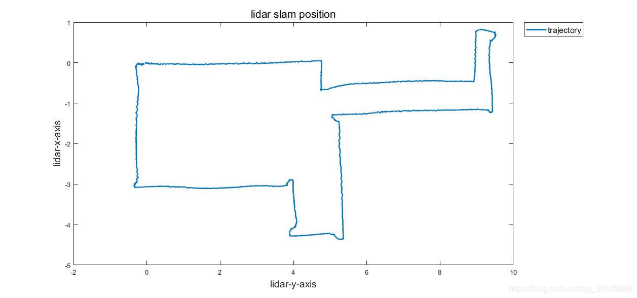
图中的拐点处,如(0.2,9.7)处出现圆弧,是因为雷达进行了旋转(rotation),并且和旋转速度有一定关系。
接下来准备测试引入IMU数据的算法运行结果,IMU来源为pixhawk飞控中的数据。