一. 开发平台与工具:
1. 平台: STM32F103C8T6 48PIN工控板和自己设计的STM32开发板
2. 软件: MDK5 UVision V5.14.0.0
3. PACK: STM32F1xx_DFP——1.0.5(2014-03-14)
4. 其它:USB转串口,ST-Link下载器,
USB-CAN Adapter(比较便宜的购买链接https://item.taobao.com/item.htm?spm=a1z09.2.0.0.549a3c95khWWbw&id=557749735449&_u=du6q5o455a0)用于直接监视CAN口发出的数据,上位机有两个,一个是EmbededConfig for USB2CAN 配置串口、串口波特率、CAN速率等,另一个是EmbededDebug V2.0监视CAN口数据;使用顺序是先配置后查看CAN数据。
二. CAN总线的介绍简略:
bxCAN 是基本扩展 CAN (Basic Extended CAN) 的缩写,它支持 CAN 协议 2.0A 和 2.0B 。它的设计目标是,以最小的 CPU 负荷来高效处理大量收到的报文。它也支持报文发送的优先级要求(优先级特性可软件配置)。
对于安全紧要的应用,bxCAN 提供所有支持时间触发通信模式所需的硬件功能。
主要特点
· 支持 CAN 协议 2.0A 和 2.0B 主动模式
· 波特率最高可达 1 兆位 / 秒
· 支持时间触发通信功能
发送
· 3 个发送邮箱
· 发送报文的优先级特性可软件配置
· 记录发送 SOF 时刻的时间戳
接收
· 3 级深度的2个接收 FIFO
· 14 个位宽可变的过滤器组 - 由整个 CAN 共享
· 标识符列表
· FIFO 溢出处理方式可配置
· 记录接收 SOF 时刻的时间戳
可支持时间触发通信模式
· 禁止自动重传模式
· 16 位自由运行定时器
· 定时器分辨率可配置
· 可在最后 2 个数据字节发送时间戳
管理
· 中断可屏蔽
· 邮箱占用单独 1 块地址空间,便于提高软件效率
更多STM32 CAN总线介绍详见:STM32中文参考手册_V10.pdf 或 STM32F10XXX-RM0008 Reference Manual 英文版
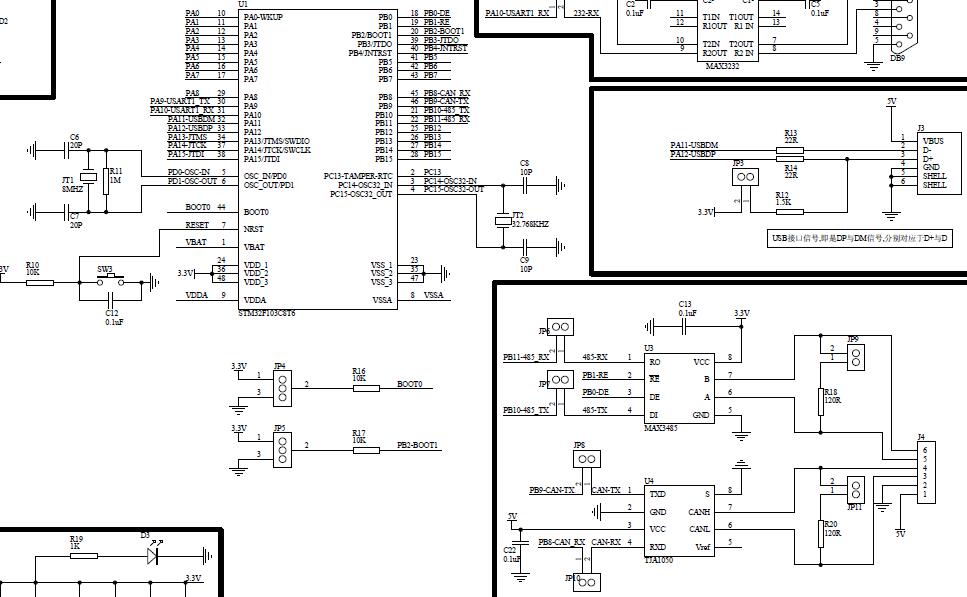
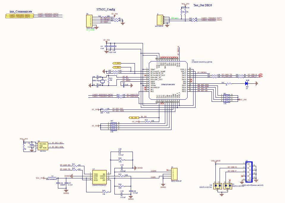
三. 遇到的问题分析与解决:手上有两块STM32的板子,一个是网上买的MINI STM32工控板,另一个是自己公司设计的板子。二者有所不同,大致有两点,第一是串口,工控板用的是USART1 且用的是GPIO PA9(TX)和PA10(RX),自设板用的是USART2 且用的是GPIO PA2(TX)和PA3(RX);第二是CAN口管脚不同,工控板用的是复用功能映射到PB8(RX)和PB9(TX),而自设板用的是PA11(RX)和PA12(TX)。下图所示,两块板子部分原理图:
工控板
自设板
现在我是在工控板测试代码基础上,用到自设板上,实现PC端串口与STM32 CAN双向通信,要做的是将USART和CAN口的GPIO配置对应到自设板上。
首先,串口GPIO配置:
工控板
void USART1_Config(void)
{
	GPIO_InitTypeDef GPIO_InitStructure;
	USART_InitTypeDef USART_InitStructure;

	/* config USART1 clock */
	RCC_APB2PeriphClockCmd(RCC_APB2Periph_USART1 | RCC_APB2Periph_GPIOA, ENABLE);

	/* USART1 GPIO config */
   /* Configure USART1 Tx (PA.09) as alternate function push-pull */
  GPIO_InitStructure.GPIO_Pin = GPIO_Pin_9;
  GPIO_InitStructure.GPIO_Mode = GPIO_Mode_AF_PP;
  GPIO_InitStructure.GPIO_Speed = GPIO_Speed_50MHz;
  GPIO_Init(GPIOA, &GPIO_InitStructure);
  /* Configure USART1 Rx (PA.10) as input floating */
  GPIO_InitStructure.GPIO_Pin = GPIO_Pin_10;
  GPIO_InitStructure.GPIO_Mode = GPIO_Mode_IN_FLOATING;
  GPIO_Init(GPIOA, &GPIO_InitStructure);

	/* USART1 mode config */
	USART_InitStructure.USART_BaudRate = 115200;
	USART_InitStructure.USART_WordLength = USART_WordLength_8b;
	USART_InitStructure.USART_StopBits = USART_StopBits_1;
	USART_InitStructure.USART_Parity = USART_Parity_No ;
	USART_InitStructure.USART_HardwareFlowControl = USART_HardwareFlowControl_None;
	USART_InitStructure.USART_Mode = USART_Mode_Rx | USART_Mode_Tx;
	USART_Init(USART1, &USART_InitStructure);
  USART_Cmd(USART1, ENABLE);

	/* Enable the EVAL_COM1 Transmit interrupt: this interrupt is generated when the
     EVAL_COM1 transmit data register is empty */
  //USART_ITConfig(USART1, USART_IT_TXE, ENABLE);

  /* Enable the EVAL_COM1 Receive interrupt: this interrupt is generated when the
     EVAL_COM1 receive data register is not empty */
  USART_ITConfig(USART1, USART_IT_RXNE, ENABLE);
}

/***************USART1 ÅäÖÃÖжϷ½Ê½·¢ËͽÓÊÕÊý¾Ý******************************/
void USART1_NVIC_Configuration(void)
{
  NVIC_InitTypeDef NVIC_InitStructure;

  /* Enable the USARTx Interrupt */
  NVIC_InitStructure.NVIC_IRQChannel = USART1_IRQn;
  NVIC_InitStructure.NVIC_IRQChannelPreemptionPriority = 0;
  NVIC_InitStructure.NVIC_IRQChannelSubPriority = 0;
  NVIC_InitStructure.NVIC_IRQChannelCmd = ENABLE;
  NVIC_Init(&NVIC_InitStructure);
}

/****************USART1 ÖжϺ¯Êý***************************/
void USART1_IRQHandler(void)
{
	if(USART_GetITStatus(USART1, USART_IT_RXNE) != RESET)
	{
		RxBuffer[RxCounter++] = (USART_ReceiveData(USART1));
	}
}
USART1_Config()用于USART1的GPIO配置,配置到
* | PA9 - USART1(Tx) |
* | PA10 - USART1(Rx) |
* ------------------------
USART1_NVIC_Configuration() 用于USART1设置中断方式接受发送数据
USART1_IRQHandler()用于USART1中断接受函数
自设板
void USART2_Config(void)
{
	GPIO_InitTypeDef GPIO_InitStructure;
	USART_InitTypeDef USART_InitStructure;

	/* config USART2 clock */
	//RCC_APB2PeriphClockCmd(RCC_APB2Periph_USART1 | RCC_APB2Periph_GPIOA, ENABLE);
	RCC_APB1PeriphClockCmd(RCC_APB1Periph_USART2 , ENABLE);
	RCC_APB2PeriphClockCmd(RCC_APB2Periph_GPIOA, ENABLE);

	/* USART2 GPIO config */
   /* Configure USART2 Tx (PA.02) as alternate function push-pull */
  GPIO_InitStructure.GPIO_Pin = GPIO_Pin_2;
  GPIO_InitStructure.GPIO_Mode = GPIO_Mode_AF_PP;
  GPIO_InitStructure.GPIO_Speed = GPIO_Speed_50MHz;
  GPIO_Init(GPIOA, &GPIO_InitStructure);
  /* Configure USART2 Rx (PA.03) as input floating */
  GPIO_InitStructure.GPIO_Pin = GPIO_Pin_3;
  GPIO_InitStructure.GPIO_Mode = GPIO_Mode_IN_FLOATING;
  GPIO_Init(GPIOA, &GPIO_InitStructure);

	/* USART2 mode config */
	USART_InitStructure.USART_BaudRate = 115200;
	USART_InitStructure.USART_WordLength = USART_WordLength_8b;
	USART_InitStructure.USART_StopBits = USART_StopBits_1;
	USART_InitStructure.USART_Parity = USART_Parity_No ;
	USART_InitStructure.USART_HardwareFlowControl = USART_HardwareFlowControl_None;
	USART_InitStructure.USART_Mode = USART_Mode_Rx | USART_Mode_Tx;
	USART_Init(USART2, &USART_InitStructure);
	USART_Cmd(USART2, ENABLE);

	/* Enable the EVAL_COM1 Transmit interrupt: this interrupt is generated when the
     EVAL_COM1 transmit data register is empty */
  //USART_ITConfig(USART1, USART_IT_TXE, ENABLE);

  /* Enable the EVAL_COM1 Receive interrupt: this interrupt is generated when the
     EVAL_COM1 receive data register is not empty */
  //USART_ITConfig(USART1, USART_IT_RXNE, ENABLE);
	USART_ITConfig(USART2, USART_IT_RXNE, ENABLE);
}


/***************USART2 ÅäÖÃÖжϷ½Ê½·¢ËͽÓÊÕÊý¾Ý******************************/
void USART2_NVIC_Configuration(void)
{
  NVIC_InitTypeDef NVIC_InitStructure;

  /* Enable the USARTx Interrupt */
  NVIC_InitStructure.NVIC_IRQChannel = USART2_IRQn;
  NVIC_InitStructure.NVIC_IRQChannelPreemptionPriority = 0;
  NVIC_InitStructure.NVIC_IRQChannelSubPriority = 0;
  NVIC_InitStructure.NVIC_IRQChannelCmd = ENABLE;
  NVIC_Init(&NVIC_InitStructure);
}

/****************USART2 ÖжϺ¯Êý***************************/
void USART2_IRQHandler(void)
{
	if(USART_GetITStatus(USART2, USART_IT_RXNE) != RESET)
	{
		RxBuffer[RxCounter++] = (USART_ReceiveData(USART2));
	}
}
USART2_Config()用于USART2的GPIO配置,配置到
* | PA2 - USART2(Tx) |
* | PA3 - USART2(Rx) |
* ------------------------
USART2_NVIC_Configuration() 用于USART2设置中断方式接受发送数据
USART2_IRQHandler()用于USART2中断接受函数
工控板
/*CAN GPIO ºÍʱÖÓÅäÖà */
void CAN_GPIO_Config(void)
{
GPIO_InitTypeDef GPIO_InitStructure;
/* ¸´Óù¦ÄܺÍGPIOB¶Ë¿ÚʱÖÓʹÄÜ*/
RCC_APB2PeriphClockCmd(RCC_APB2Periph_AFIO | RCC_APB2Periph_GPIOB, ENABLE);
/* CAN1 Ä£¿éʱÖÓʹÄÜ */
RCC_APB1PeriphClockCmd(RCC_APB1Periph_CAN1, ENABLE);
/* Configure CAN pin: RX */ // PB8
GPIO_InitStructure.GPIO_Pin = GPIO_Pin_8;
GPIO_InitStructure.GPIO_Speed = GPIO_Speed_50MHz;
GPIO_InitStructure.GPIO_Mode = GPIO_Mode_IPU; // ÉÏÀÊäÈë
GPIO_Init(GPIOB, &GPIO_InitStructure);
/* Configure CAN pin: TX */ // PB9
GPIO_InitStructure.GPIO_Pin = GPIO_Pin_9;
GPIO_InitStructure.GPIO_Mode = GPIO_Mode_AF_PP; // ¸´ÓÃÍÆÍìÊä³ö
GPIO_Init(GPIOB, &GPIO_InitStructure);
//#define GPIO_Remap_CAN GPIO_Remap1_CAN1 ±¾ÊµÑéûÓÐÓõ½ÖØÓ³ÉäI/O
GPIO_PinRemapConfig(GPIO_Remap1_CAN1, ENABLE);
}void CAN_GPIOA_Config(void)
{
GPIO_InitTypeDef GPIO_InitStructure;
/* CAN Periph clock enable */
RCC_APB2PeriphClockCmd(RCC_APB2Periph_GPIOA ,ENABLE);
// RCC_APB2PeriphClockCmd(RCC_APB2Periph_GPIOA | RCC_APB2Periph_AFIO,ENABLE);
RCC_APB1PeriphClockCmd(RCC_APB1Periph_CAN1, ENABLE);
/* Configure CAN pin: TX */
GPIO_InitStructure.GPIO_Pin = GPIO_Pin_12;
GPIO_InitStructure.GPIO_Speed = GPIO_Speed_50MHz;
GPIO_InitStructure.GPIO_Mode = GPIO_Mode_AF_PP;
GPIO_Init(GPIOA, &GPIO_InitStructure);
/* Configure CAN pin: RX */
GPIO_InitStructure.GPIO_Pin = GPIO_Pin_11;
GPIO_InitStructure.GPIO_Speed = GPIO_Speed_50MHz;
GPIO_InitStructure.GPIO_Mode = GPIO_Mode_IPU;
GPIO_Init(GPIOA, &GPIO_InitStructure);
//GPIO_PinRemapConfig(GPIO_Remap1_CAN1 , ENABLE);
} 就是这里!!!!!!!!!!!!!!!!!!!!!!!!!!!!!!!!
出现几个小问题,但是却是致命的问题!!!!!!!!!!!!!!!!!!!
/******************************************************************************************/
第一配置GPIO_Speed:
GPIO_InitStructure.GPIO_Speed = GPIO_Speed_50MHz; //配置GPIO_Speed为50MHz如果配置GPIO时,省略这一步,会导致CAN口发送不出数据,工控板的配置是放在LED 的GPIO配置中,一开始忽略了这一点,之后用排除法试出来的;
第二配置复用功能和映射与否:
// RCC_APB2PeriphClockCmd(RCC_APB2Periph_AFIO,ENABLE); //复用功能时钟使能//GPIO_PinRemapConfig(GPIO_Remap1_CAN1 , ENABLE); //重映射I/O CAN使能上面两个被注释掉了,是由于:用PA11和PA12 用的是CAN的默认端口,而用PB8和PB9是用CAN的复用功能重映射端口。
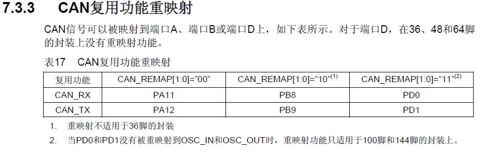
具体:
-------------------------------------------------------------------------
默认模式
/* Configure CAN pin: RX */
GPIO
_InitStructure.GPIO_Pin = GPIO_Pin_11;
GPIO_InitStructure.GPIO_Speed = GPIO_Speed_50MHz;
GPIO_InitStructure.GPIO_Mode = GPIO_Mode_IPU;
GPIO_Init(GPIOA, &GPIO_InitStructure);
/* Configure CAN pin: TX */
GPIO_InitStructure.GPIO_Pin = GPIO_Pin_12;
GPIO_InitStructure.GPIO_Speed = GPIO_Speed_50MHz;
GPIO_InitStructure.GPIO_Mode = GPIO_Mode_AF_PP;
GPIO_Init(GPIOA, &GPIO_InitStructure);
------------------------------------------------------------------------
重定义地址1模式
/* Configure CAN pin: RX */
//GPIO_InitStructure.GPIO_Pin = GPIO_Pin_8;
//GPIO_InitStructure.GPIO_Speed = GPIO_Speed_50MHz;
//GPIO_InitStructure.GPIO_Mode = GPIO_Mode_IPU;
//GPIO_Init(GPIOB, &GPIO_InitStructure);
/* Configure CAN pin: TX */
//GPIO_InitStructure.GPIO_Pin = GPIO_Pin_9;
//GPIO_InitStructure.GPIO_Speed = GPIO_Speed_50MHz;
//GPIO_InitStructure.GPIO_Mode = GPIO_Mode_AF_PP;
//GPIO_Init(GPIOB, &GPIO_InitStructure);
/* Configure CAN Remap 重影射 */
//GPIO_PinRemapConfig(GPIO_Remap1_CAN, ENABLE);
-------------------------------------------------------------------------
重定义地址2模式
/* Configure CAN pin: RX */
//GPIO_InitStructure.GPIO_Pin = GPIO_Pin_0;
//GPIO_InitStructure.GPIO_Speed = GPIO_Speed_50MHz;
//GPIO_InitStructure.GPIO_Mode = GPIO_Mode_IPU;
//GPIO_Init(GPIOD, &GPIO_InitStructure);
/* Configure CAN pin: TX */
//GPIO_InitStructure.GPIO_Pin = GPIO_Pin_1;
//GPIO_InitStructure.GPIO_Speed = GPIO_Speed_50MHz;
//GPIO_InitStructure.GPIO_Mode = GPIO_Mode_AF_PP;
//GPIO_Init(GPIOD, &GPIO_InitStructure);
/* Configure CAN Remap 重影射 */
//GPIO_PinRemapConfig(GPIO_Remap2_CAN, ENABLE);
-------------------------------------------------------------------------
设置完 CAN 的引脚之后还需要打开 CAN 的时钟:
/* CAN Periph clock enable */
RCC_APB1PeriphClockCmd(RCC_APB1Periph_CAN, ENABLE);
第三CAN硬件部分:
一开始对CAN硬件部分没有过多的了解,后面经过一系列的试验,发现:
1. 如果STM32 CAN TX和RX没有和CAN收发器连接的情况下,STM32的CAN TX和RX是没用数据发出的;
2. STM32 CAN TX和RX必须要与CAN收发器的TX和RX对应,即TX接TX,RX接RX,否则CAN没有数据发出,说明:之所以说这个问题,不知道你们有没有注意到,我的自设板CAN收发器TX和RX是反接的;
3. STM32F103C8T6-LQFP48 的CAN口和USB口复用,即用CAN口是需要将USB口断开,防止有所影响;
4. 是我本身设备问题,我的自设板用的12V电源是我自己焊接的,不太可靠,电源12V时有时无的,所以最好烧写程序的时候点亮一个LED灯,可以显示板子的工作状态;
5. 工控板上CAN收发器是用TJA1050 是5V供电的,自设板用SN65HVD234 3.3-V CAN Bus Transceivers,之前有所顾虑,怕CAN收发器不一样会导致其它后果,之后发现没有问题。
以上为本人的一点心得,走了很多弯路。。。记录点滴,以此自励。