
读取字节:
读取字节:
uint8_t Read_Byte(){
uint8_t i=0;
unsigned char temp=0x00;
Set(STB);
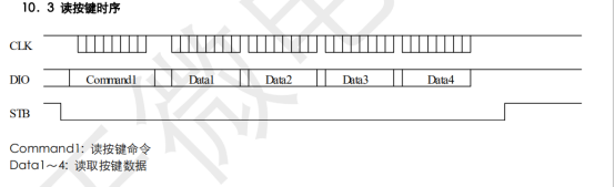
Write_Byte(0x42); //传按键检测命令
delay_us(1); //与之后的读取要至少有1us的延时
Reset(STB);
GPIO1(); //将GPIO口从输出变为输入 !!!
// Set(DIO);
Reset(CLK);
delay_us(2);
for(i=0;i<8;i++){ //一次读取8bit
Set(CLK); //拉高CLK开始读取数据
//read
delay_us(4);
temp = temp>>1;
if(Get(DIO) !=0 ){
temp = (temp |0x80 );
}
else {
temp &= 0x7f;
}
Reset(CLK);
delay_us(4);
}
Set(CLK);
Set(STB);
return temp;
}
判断按键:
unsigned char  Read_Key(){

    uint8_t z=0;
	uint8_t k=0;


//因为我只有4个按键,所以根据硬件原理图读一次即可
        z = Read_Byte();
		if(z == 0x08)
			k = 1 ;
		else if(z == 0x04)
			k = 2;
		else if(z == 0x02)
			k = 3;
		else if (z == 0x01)
			k =4;

		return k;

}
以上是读取按键操作。
以数组图表方式操作所有灯:

unsigned char disa[16]={0};
//通过对数组16位赋值SEG状态,再通过自动地址方式给16位GPIO发送对应的SEG数据位,从而达到一个个控制灯的亮灭。

//num为GPIO,n为SEG,z为ON或OFF决定开还是关
void  LED_a(unsigned char num,uint16_t n,uint16_t z)
{

	if(z == ON) {
		disa[2*num -2] |= SEG[n];		//数组中是计算对应的GPIO
		display(disa);
	}
	else if(z== OFF) {
		disa[2*num-2] &= SEG_OF[n];
		display(disa);
	}


}
例如:
void  process()
{
	LED_a(2,2,ON);
	while(1) {

		key1 = Read_Key();

		GPIO_Config();

			if(key1 == 1) {
				LED_a(2,7,ON);
				LED_a(3,7,OFF);
				LED_a(5,6,OFF);
				LED_a(1,7,OFF);
			}
			else if(key1 == 2) {
				LED_a(1,7,ON);
				LED_a(3,7,OFF);
				LED_a(5,6,OFF);
				LED_a(2,7,OFF);
			}
			else if(key1 == 3) {
				LED_a(5,6,ON);
				LED_a(1,7,OFF);
				LED_a(2,7,OFF);
			}
			else if(key1 == 4) {
				LED_a(3,7,ON);
				LED_a(1,7,OFF);
				LED_a(2,7,OFF);
			}


		delay_ms(1000);
	}


}
注意事项:
1.一定要按照时序图走,注意是CLK拉高时发送和接受数据
2.延时延时延时!
3.注意clk的时间,给予至少2.5us的延时
4.做表,将对应每个灯的地址做表,方便控制。
5.读懂手册