In this lab, we will study the Zynq SoC’s interrupt system structure. The Zynq SoC uses a Generic Interrupt Controller (GIC) to process interrupts. The procedures needed to implement an interrupt-driven system are explained in details. An interrupt-driven application is developed with detailed interrupt handlers (ISRs) and interrupt setup functions.

Lab4 Design Flow

Lab4 Block Diagram

Lab4 Board Interface
The GIC is circled in red in the figure below:

Zynq Architecture- GIC circled in red
The GIC handles interrupts from the following sources:
- Software-generated interrupts – There are 16 such interrupts for each processor. They can
interrupt one or both of the Zynq SoC’s ARM® Cortex™-A9 processor cores. - Shared peripheral interrupts – Numbering 60 in total, these interrupts can come from the
I/O peripherals, or to and from the programmable logic (PL) side of the device. They are
shared between the Zynq SoC’s two CPUs. - Private peripheral interrupts – The five interrupts in this category are private to each
CPU—for example CPU timer, CPU watchdog timer and dedicated PL-to-CPU interrupt.

Interrupt System Structure for the Zynq
When an interrupt occurs within the Zynq SoC, the concerned processor will take the following actions:
1.The interrupt is shown as pending.
2.The processor stops executing the current program.
3.The processor saves the state of the program in the stack to allow processing to continue once it has handled the interrupt.
4. The processor executes the interrupt service routine (ISR), which defines how the interrupt is to be handled.
5. The processor resumes operation of the interrupted program after restoring it from the stack.
It is important to keep in mind that interrupts are asynchronous events, it is possible for multiple interrupts to occur at the same time. To address this issue, the processor prioritizes interrupts such that it can service the highest-priority interrupt pending first. With this being said, it should be clear by now why one needs to write two functions to handle an interrupt: First, an interrupt service routine(ISR)(also known as the interrupt handler) to define the actions that will take place when the interrupt occurs, and second, an interrupt setup function to configure the interrupt settings (priority, level sensitivity for hardware interrupt , etc..).
For this lab, the hardware setup contains a GPIO controller and the ZedboardOLED controller, both connected to the PS through AXI interconnect as illustrated in the block diagram above. The PS configuration is going to be set up to accept interrupts from the PL.
On the PL side of the chip, the GPIO will be configured to support interrupts and generate an interrupt signal every time a push button is pressed. The OLED will act as a terminal or a monitor, it is going to help us in observing the flow of execution. The main program is a simple infinite loop that displays the English alphabet sequentially (A-Z) and once it reaches the letter “Z” it rolls back to “A”. The main program will be halted, and the interrupt handler (ISR) will be executed every time an interrupt occurs (i.e. a push button is pressed). In the ISR, the GPIO’s data register will be read to figure out which button was pressed out of the five push buttons (BTNC, BTND, BTNR, BTNL, BTNU), then this button will be displayed on the OLED using the print_message() function of the ZedboardOLED driver. Upon completion serving the interrupt, the main program will resume at a letter exactly after the letter it was halted at. For instance, if we pressed a button when the letter “D” is being displayed on the OLED, the main program should resume at letter “E”. The next figure shows a simplified flowchart of the application’s behavior (Typical interrupt driven application behavior).

Lab4 Application Flow Chart
Objectives
1.Implement a demonstrative interrupt-driven embedded system.
2.Explore the generic interrupt controller of the Zynq SoC.
3.learn to differentiate between the different sources of interrupts within the Zynq SoC.
4.Expand the functionality of the GPIO controller to support interrupts.
5.Write an interrupt handler (aka ISR) and an interrupt setup function that utilizes the generic interrupt controller(SCUGIC) driver , the PS and the GPIO interrupt related functions.
6.Learn how to increase the stack and heap memory allocated for the program’s execution.
Procedures
A-Create a project in Vivado to target the Zedboard
Follow the same five steps in Procedures-A of Lab1. However, in step3 name your project “lab4”.
B-Create ARM processor system with interrupt support
1.Click on Create Block Design in IP Integrator available on the left top side of Vivado.
2.Type a name for the module and click OK. For this example, use the name: “zynq_interrupt_system”.

Create a Block Design
3. Add the ZYNQ7 Processing System by lunching the Add IP wizard![]() and typing “zynq”.
and typing “zynq”.

ZYNQ7 Processing System
4.Double click on the ZYNQ7 Processing System block, to open the Re-Customize IPwindow. Select Interrupts from the Page Navigator on the left-hand side and expand the menu on the right. Since we want to allow interrupts from the programmable logic to the processing system, tick the box to enable Fabric Interrupts; fabric is another name for the PL; then tick to enable the shared interrupt port IRQ_F2P[15:0] (read as Interrupt Request_Fabric to Processing System) as show in the figure below. This means interrupts from the PL can be connected to the interrupt controller within the Zynq PS. Also, make sure to enable URAT1 in MIO Configration (In case we wanted to use a terminal).

Enable Fabric Interrupts
Given that you followed the above directions correctly, the Zynq PS system should look identical to the one shown below:

ZYNQ7 Processing System with Fabric Shared Interrupt Port Enabled
However, If it is not identical, double click on the block again to re-customize it, and turn ON/OFF the affiliated settings. Notice the shared interrupt port is enabled (enclosed in a red rectangle). This is the port that the PL generated interrupts should be connected to.
Click Run Block Automation in the green information bar. Make sure to deselect the option Apply Board Preset otherwise all the customization we just did will be lost. Click OK.

Block Automation
Notice that the FIXED_IO and DDR are now connected to external ports.

ZYNQ7 Processing System after Block Automation
C-Add a GPIO controller and enable its interrupt port
1.Add a GPIO controller, by lunching the Add IP wizard![]() and typing “gpio”.
and typing “gpio”.
2.Click on Run Connection Automation,select GPIO first and make sure that btns_5bits is selected in the Select Board Part Interface.

Run Connection Automation – GPIO Page
Also make sure that S_AXI is selected and the Clock Connection is set to Auto.

Run Connection Automation- S_AXI Page
Click OK to automatically connect the slave interfaces of the GPIO to the master interface of the PS through the AXI Interconnect block, and also to connect its external ports to the five push buttons on the Zedboard.
Click on the Regenerate Layout![]() to arrange the blocks in your design.
to arrange the blocks in your design.

Block Diagram After Adding GPIO
3.Double click on the GPIO block to open the Re-customize IP window. Click the IP Configuration tab and enable interrupts by clicking in the box highlighted in figure below, then click OK. This will add an interrupt request port to the GPIO block.

Enable Interrupt on GPIO
4.Make a connection between the newly created interrupt request port of the GPIO block and the shared interrupt port of the Zynq PS by dragging the mouse’s cursor.(hover the mouse until its shape changes to a pencil shape)

Connect GPIO interrupt request port to the shared interrupt port of PS
D-Add the ZedboardOLED controller
Follow all steps in Procedures-D and Procedures-E of the previous lab (Customized Hardware Integration) to add the ZedboardOLED controller and connected to the system and the OLED. The block design should look like this after adding the IP.

Block Diagram After Adding Zedboard OLED
E-Generate Bitstream
1.In the Sources pane, Right click on zynq_interrput_system.bd and select Create HDL Wrapper to create the top level Verilog file from the block diagram. Select Let Vivado manage wrapper and auto-update when prompted with the next message. Notice that zynq_interrput_system_wrapper.v got created and placed at the top of the design sources hierarchy.
2.In the Program and Debug section in the Flow Navigator pane, click Generate Bitstream. A dialog box will appear to ask you to save the modification you made, click Save .

Generating Bitstream
Generating the Bitstream may take a while to complete, depending on the performance of your machine. After the bitstream generation completes select View Reports in the dialog box, and click OK.
F-Export hardware design to SDK
1.Click File > Export > Export Hardware, make sure you select Include bitstream.
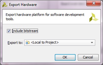
Export Hardware to SDK
2.Select File>Launch SDK. This will open up Launch SDK dialog, leave default options as as, and click OK. All the hardware files related to design has now been exported to SDK and we can work on the software.
We are now done with the hardware configuration of the system. You may close Vivado.
G-Working with SDK
1.In SDK, select File > New > Application Project.
2.In the next window, enter the parameters as provided in the snapshot below:

New Standalone C Project
In the next window, select Empty Application from the available templates and click Finish. This will compile the BSP and the related drivers.
3.Expand interrupt_test directory , right click on src directory , New->Source File.

New C Source File
4.In the next window that shows up type “lab4.c” in the source file and click Finish. This will create an empty C file in the src directory.

lab4.c empty source file created in SDK
5. Paste the content of lab4.c ( Available on my Github page) in in the editor view of lab4.c of SDK , and click on Save ![]() or hit (Ctrl+S) , by doing so both the lab4 application, and its BSP are compiled automatically and the executable .elf file is generated( the default settings of SDK triggers compilation with save). This is the executable file that the ARM processor on the PS side of the Zynq will execute.
or hit (Ctrl+S) , by doing so both the lab4 application, and its BSP are compiled automatically and the executable .elf file is generated( the default settings of SDK triggers compilation with save). This is the executable file that the ARM processor on the PS side of the Zynq will execute.
There are four functions in application lab4.c : Function main () first initializes the peripherals & set directions of gpio, then it calls IntcInitFunction(), which in turns initialize interrupt controller, register GPIO interrupt handler( which means associate a function with the interrupt coming from GPIO), and enable GPIO interrupts in the GPIO itself and in the GIC. IntcInitFunction() also calls a sub-function InterruptSystemSetup() to register GIC interrupt handler.
IntcInitFunction() returns to main() which enters an infinite loop (lines 140-145). In the infinite loop it function print_message() is called to display the alphabet on the OLED. When an interrupt is triggered ( by pressing a push button in this example) the processor stop executing main() and move its attention to the function associated with the source of interrupt ( in our case its the BTN_Intr_Handler) . BTN_Intr_Handler() reads the GPIO’s data register to figure out which button was pressed out of the five push buttons (BTNC, BTND, BTNR, BTNL, BTNU) and then print this button on the OLED using the print_message() function of the ZedboardOLED driver.

Lab4.c Application
In this lab, the stack will be used extensively to swap in and out different parts of the code ; namely the main function and ISR function; therefore we need to enlarge the memory reserved for the stack just to stay on the safe side. This can be done by right click on the interrupt_test directory and select Generate Linker Script. In the Linker script we can choose where our program will reside( DDR memory or RAM ) and also we can configure the head and stack memories allocated for our application.

Generate a linker script
Change the stack and heap size from 1KB to 10 KB by adding a zero at the end of the 1024 number. The stack and heap memories are used to save information related to function calls and returns, which are happening quite often in our code. Click Generate and select Yes to overwrite existing file.
H-Download bitstream and run the application (Hardware Verification)
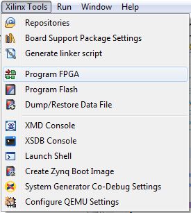
1.Select Xilinx Tools-> Program FPGA to download the Bitstream (this will take few seconds).
2.Select interrupt_test project directory-> Run As-> Launch on Hardware (GDB) to run the oled_test application on the ARM processor.
Once the application is loaded, you should observe the English alphabet being printed at position 0 of page 0 of the OLED. If a button from the five push buttons of Zedboard is pressed this would call the ISR of the GPIO which displays which button was pressed on the OLED and then it returns back to the main program to resume printing the letter following the one it was interrupted at. See the demo video.
By this you have completed Lab4-Interrupts. You can find the complete solution of this lab in here.