In this lab, we will examine the rich set of hardware timers available on the Zynq SoC chip and their appropriate usages. The AXI-Timer is selected as a case study, which is added to the PL-side of the chip. The timer will be utilized to generate a precise periodic interrupt every one second, which is used in implementing a real time clock.

Lab5 Design Flow

Lab5 Block Diagram

Lab5 Board Interface
Precise timing is a crucial need in almost all embedded systems. Hardware timers provides such service. The Zynq family of chips is rich with different types of timers: each Cortex-A9 processor has its own private 32-bit timer and 32-bit watchdog timer.Whereas, on the processor system level, there is a 24-bit System Watch Dog Timer (SWDT) and two 16-bit Triple Timer/Counters(TTC). The SWDT is usually used for signaling catastrophic system failure events, such as CLK PS failure, and can be used to perform an automated system reset, on the other hand, the TTC is a more capable timer that can be used for variety of tasks, such as : PWM generation; waveform generation; a scheduler that generates different interrupts at specified count value.

Hardware Timers on the Zynq

Zynq Architecture with hardware timers highlighted
In addition to this rich set of hardware timers, extra timers can be added in the PL-side of the chip, and connected to the PS side through an AXI interconnect.
In this lab, the AXI-Timer is used, which is added in the PL-side of the chip. The timer is utilized to generate precise periodic interrupt every one second, to be used in implementing a real time clock. The hardware setup for this lab is similar to the one of the previous lab, except the addition of the AXI-Timer. However, the software differs a bit. In here the push buttons are used to set and/or reset the minutes and hours of the clock. The OLED is used to display the clock, while the newly added AXI-Timer is responsible for incrementing the seconds digits of the clock in an accurate manner. The format of the clock is HH:MM:SS. Since the hardware setup of this lab highly resembles the setup of the previous lab(Lab4 Interrupts), we will build this lab as an upgrade of the former one.
Objectives
1.Introduce the different hardware timers’ resources on the Zynq family.
2.Examine the AXI-Timer in depth, utilize it to generate periodic interrupts every one second.
3.Build an interrupt-driven system with multiple sources of interrupts.
4.Use Vivado basic logic blocks to perform basic logical operations, such as concatenation.
5.Learn how to extend functionality of an already built system.
Procedures
A-Copy lab4 content into a new directory
1.Create a new folder in your “C:\embeddedcentric” directory, name this folder “lab5″.

Create a new folder
2.Open the previous lab directory “C:\embeddedcentric\lab4“. Copy all content of that directory EXCEPT “lab4.sdk”. (Use the Ctrl Key to select multiple files ). Note: ( If you don’t have lab4 files, you can download it from my GitHub page).

Copy Lab4 content (EXCEPT SDK Project)
3.Paste the content in the newly created folder “C:\embeddedcentric\lab5“.

Moving the content of lab4
4.Open Vivado by double clicking on “lab4.xpr”.
IMPORTANT NOTE: Do not rename the Vivado project file. Keep it as is “lab4.xpr” even though its the fifth lab. Trying to rename this file would result in a mess later on.
By this, you have copied the previous lab files into a new directory, and opened it using Vivado.
B-Add and Configurie an AXI-Timer
1.Double click on zynq_interrupt_system_i.bd in the Sources pane to open up the block diagram.

Open the Block Diagram
2.In the diagram view, right-click anywhere and select Add IP![]() . Enter “timer” in the search field. Select and double click on AXI Timer to add it.
. Enter “timer” in the search field. Select and double click on AXI Timer to add it.

Add AXI-Timer
3.Notice that Designer Assistance is available in the upper left side of the diagram view. Click on Run Connection Automation. The Run Connection Automation window will pop up, leave default options as is, and click OK.

Run Connection Automation-AXI Timer
The clock driving the AXI timer is the default FCLK_CLK0 of 50 Mhz. It is accessible in the PS Re-customize IP ->Clock Configuration->PL Fabric Clocks->FCLK_CLK0

PL Fabric Clock
FCLK_CLK0 can be modified to the desired value to meet your timing requirement. The value of the frequency driving the AXI-Timer determines the resolution of your timer and the maximum time it can measure without overflow. The allowable values of frequency are ranging from 0.1 to 250 Mhz. A separate clock source could be enabled from the available four PL Fabric Clocks to tailor other components’ demands.
4.The AXI Timer features an interrupt port, which requires connection to the Zynq PS. However, we already have the GPIO interrupt connected to the interrupt request port of the PS (done in previous lab). This port is actually a shared interrupt port that can support up to 16 interrupts, and it accepts multiple interrupts via one bus. We therefore require an additional IP block to concatenate these two interrupt signals(the GPIO and AXI-Timer interrupts) into one bus. In the diagram view, right-click anywhere and select Add IP![]() . Enter “concat” in the search field and add the Concat IP by double clicking on it. “concat” is an acronym for concatenation, which can be defined as the process of creating a vector(bus) from a collection of independent signals or from smaller vectors.
. Enter “concat” in the search field and add the Concat IP by double clicking on it. “concat” is an acronym for concatenation, which can be defined as the process of creating a vector(bus) from a collection of independent signals or from smaller vectors.

Add Concat IP
5.Remove the connection to IRQ_F2P[0:0] on the Zynq PS by selecting it and pressing DELETE. Connect the output of the Concat block to IRQ_F2P[0:0] instead. Then, connect the interrupt request from the GPIO to the first input port of Concat(ip2intc_irpt-> In0[0:0]) and the interrupt from the timer to the second input port of Concat (interrupt->In1[0:0]). This create a 2 bits width bus passed to the PS through the shared interrupt signal. Right click on a free location in the diagram view and select Regenerate layout ![]() . Your block diagram should be similar to the one below:
. Your block diagram should be similar to the one below:

Block Diagram after concatenating the interrupts signals
The IRQ_F2P is a 16-bit shared interrupt line (by shared, it means available to both CPUs) from the PL to the PS (Fabric to PS- F2P). Since we have multiple sources of interrupts,and interrupts are inherently asynchronous events( They could happen at any time), this could raise the issue of having more than one interrupt happening at the same time. The solution for this issue is called prioritizing. Prioritizing gives order of precedence to multiple sources of interrupts. If two interrupts happened at the same time, the one with higher priority is processed first.
On the Zynq, prioritizing is achieved among these sixteen interrupts by placing the signal that we wish to have a higher priority in the
higher bit order. The MSB(Most Significant Bit) is assigned the highest priority, while the lowest priority is assigned to the LSB(Least Significant Bit). Therefore, we have placed the interrupt coming from the timer to In1[0:0] to give it higher priority than the one coming from the GPIO.
C-Generate Bitstream
In the Program and Debug section of the Flow Navigator pane, click Generate Bitstream. A dialog box will appear to ask you to save the modification you made, click Save .

Generating Bitstream
Generating the Bitstream may take a while to complete, depending on the performance of your machine. After the Bitstream generation completes select View Reports in the dialog box, and click OK.
D-Export hardware design to SDK
1.Click File > Export > Export Hardware, make sure you select Include bitstream.
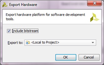
Export Hardware to SDK
2.Select File>Launch SDK. This will open up Launch SDK dialog, leave default options as as, and click OK. All the hardware files related to design have now been exported to SDK and we can work on the software.
We are now done with the hardware configuration of the system. You may close Vivado.
E-Working with SDK
1.In SDK, select File > New > Application Project.
2.In the Application Project window, enter the parameters as provided in the snapshot below:

New Standalone C Project – real_time_clock
In the next window, select Empty Application from the available templates and click Finish. This will compile the BSP and the related drivers.
3.Expand real_time_clock directory , right click on src directory , New->Source File.

New C Source File – lab5.c
4.In the next window that shows up type “lab5.c” in the source file and click Finish. This will create an empty C file in the src directory.

lab5.c empty source file created in SDK
5.Paste the content of lab5.c ( Available on my Github page) in in the editor view of lab5.c of SDK , and click on Save ![]() or hit (Ctrl+S) , by doing so both lab5 application, and its BSP are compiled automatically and the executable .elf file is generated( the default settings of SDK triggers compilation with save). This is the executable file that the ARM processor on the PS side of the Zynq will execute.
or hit (Ctrl+S) , by doing so both lab5 application, and its BSP are compiled automatically and the executable .elf file is generated( the default settings of SDK triggers compilation with save). This is the executable file that the ARM processor on the PS side of the Zynq will execute.
lab5.c is an extended version of lab4.c. The additions on top of lab4.c are enclosed by comments as show in the figure below. The additions include an interrupt handler (ISR) for the AXI-Timer and a modified interrupt setup function.

Lab5 additions on Lab4 C code
main () first initializes the GPIO and sets its direction to be input, then it initializes and configures AXI-Timer as a counting up timer with auto reload, and loads it with the value TMR_LOAD that makes it interrupt at exactly every one second. After that, it calls IntcInitFunction(), which in turns initializes GIC interrupt controller, register the GPIO and AXI-Timer interrupt handlers( which means associate functions”ISRs” to be called when an interrupt is sensed from GPIO or AXI-Timer), and enable GPIO, AXI-Timer interrupts in their controllers and in the GIC. IntcInitFunction() also calls a sub-function InterruptSystemSetup() to register GIC interrupt handler.
main() then enters an idle infinite loop (lines 241-243), where the processor is just spinning doing nothing interesting. When an interrupt is triggered either by the AXI-Timer or a push button, it will temporarily stop executing main() and move its attention to the function(ISR) associated with the source of interrupt which could be either the AXI-Timer or push buttons. Two scenarios are possible :
Scenario1 A push button was pressed: BTN_Intr_Handler() is called. It reads the GPIO’s data register to figure out which button was pressed out of the three central push buttons (BTNC, BTNR, BTNL). If it’s BNTC then the real time clock is reset, if it’s BTNL then the hours digits are incremented, if it’s BTNR then the minutes digits are incremented.
Scenario2 AXI-Timer overflow: TMR_Intr_Handler()is called. It increments the seconds and manage the display of the real time clock on the OLED.

Lab5 C Code
F-Download bitstream and run the application (Hardware Verification)
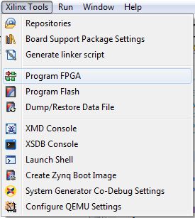
1.Select Xilinx Tools-> Program FPGA to download the Bitstream (this will take few seconds).
2.Select real_time_clock project directory-> Run As-> Launch on Hardware (GDB) to run real_time_clock application on the ARM processor.

Run Application lab5.c
Once the application is loaded, you should observe the clock running on the OLED.

Real Time Clock
If the center push button is pressed the clock is rest, the right button is to increment the minutes digits, while the left button is to increment the hours digits. See the demo video.
By this you have completed Lab5-Hardware Timers. You can find the complete solution of this lab in here.