最近开始学stm32,着实感觉到了stm32和51之间的区别,但也有联系,总我感觉32与51之间最大的区别就是在使用某个外设之前,要对该外设进行时钟的使能(以达到降低功耗的目的),和相关配置。
刚学完跑马灯,下面对跑马灯用到的对IO口的配置相关知识分别对应官方库函数和寄存器进行总结。
如有错误或不足,请在下方留言。
文章内容基于正点原子战舰。
-
IO口的状态
IO口有八大模式:─ 输入浮空( GPIO_Mode_IN_FLOATING = 0x04,)
─ 输入上拉( GPIO_Mode_IPU = 0x48,)
─ 输入下拉( GPIO_Mode_IPD = 0x28,)
─ 模拟输入(GPIO_Mode_AIN = 0x0,)
─ 开漏输出( GPIO_Mode_Out_OD = 0x14,)
─ 推挽式输出( GPIO_Mode_Out_PP = 0x10,)
─ 推挽式复用功能(GPIO_Mode_AF_PP = 0x18)
─ 开漏复用功能( GPIO_Mode_AF_OD = 0x1C,)
IO口有三种速 -2MHZ( GPIO_Speed_2MHz=1,)
-10MHz( GPIO_Speed_10MHz = 1,)
-50MHz( GPIO_Speed_50MHz=3,) //当看到这些配置相应的值是否会感到疑惑呢,稍后讲解。
-
跑马灯的原理图
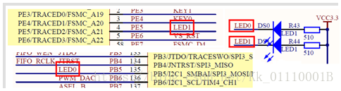
显然led的硬件连接很简单分别连接了IO口PE5和PB5,另一端串联一个电阻共同接地。
-
实验的代码分析
我们知道任何外设的驱动都要使能相应的时钟,首先看stm32系统的时钟框图
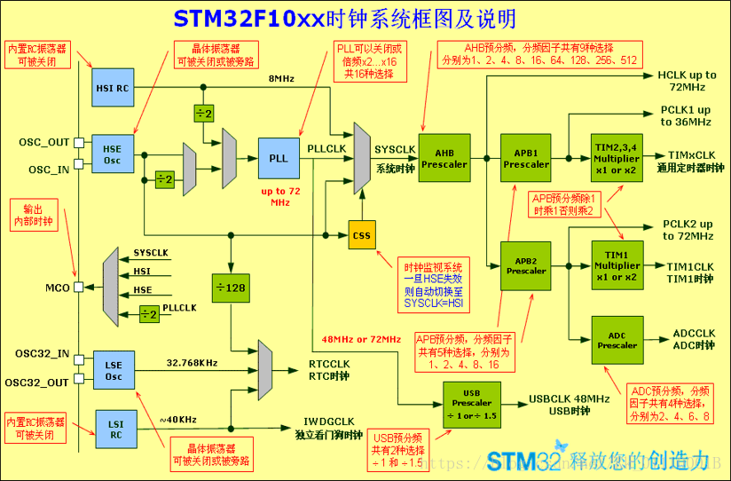
经查阅资料可知,GPIO的时钟在APB2的外设时钟使能寄存器上,相关函数的定义在stm32f10x_rcc.h中 void RCC_APB2PeriphClockCmd(uint32_t RCC_APB2Periph, FunctionalState NewState)其源代码为:
void RCC_APB2PeriphClockCmd(uint32_t RCC_APB2Periph, FunctionalState NewState)
{
  /* Check the parameters */ //检查值的有效性
  assert_param(IS_RCC_APB2_PERIPH(RCC_APB2Periph));
  assert_param(IS_FUNCTIONAL_STATE(NewState));
  if (NewState != DISABLE)
  {
    RCC->APB2ENR |= RCC_APB2Periph; //配置APB2ENBR寄存器
  }
  else
  {
    RCC->APB2ENR &= ~RCC_APB2Periph; //配置APB2ENR寄存器
  }
}

//与该函数相关的一些宏定义  检查RCC_APB2Periph参数的有效性

#define RCC_APB2Periph_AFIO              ((uint32_t)0x00000001)
#define RCC_APB2Periph_GPIOA             ((uint32_t)0x00000004)
#define RCC_APB2Periph_GPIOB             ((uint32_t)0x00000008)
#define RCC_APB2Periph_GPIOC             ((uint32_t)0x00000010)
#define RCC_APB2Periph_GPIOD             ((uint32_t)0x00000020)
#define RCC_APB2Periph_GPIOE             ((uint32_t)0x00000040)
#define RCC_APB2Periph_GPIOF             ((uint32_t)0x00000080)
#define RCC_APB2Periph_GPIOG             ((uint32_t)0x00000100)
#define RCC_APB2Periph_ADC1              ((uint32_t)0x00000200)
#define RCC_APB2Periph_ADC2              ((uint32_t)0x00000400)
#define RCC_APB2Periph_TIM1              ((uint32_t)0x00000800)
#define RCC_APB2Periph_SPI1              ((uint32_t)0x00001000)
#define RCC_APB2Periph_TIM8              ((uint32_t)0x00002000)
#define RCC_APB2Periph_USART1            ((uint32_t)0x00004000)
#define RCC_APB2Periph_ADC3              ((uint32_t)0x00008000)
#define RCC_APB2Periph_TIM15             ((uint32_t)0x00010000)
#define RCC_APB2Periph_TIM16             ((uint32_t)0x00020000)
#define RCC_APB2Periph_TIM17             ((uint32_t)0x00040000)
#define RCC_APB2Periph_TIM9              ((uint32_t)0x00080000)
#define RCC_APB2Periph_TIM10             ((uint32_t)0x00100000)
#define RCC_APB2Periph_TIM11             ((uint32_t)0x00200000)

#define IS_RCC_APB2_PERIPH(PERIPH) ((((PERIPH) & 0xFFC00002) == 0x00) && ((PERIPH) != 0x00))

//与该函数相关的枚举变量定义  检查NewState参数的有效性

typedef enum {DISABLE = 0, ENABLE = !DISABLE} FunctionalState;
#define IS_FUNCTIONAL_STATE(STATE) (((STATE) == DISABLE) || ((STATE) == ENABLE))
我们来看这个使能GPIO时钟函数的源代码,函数没有返回值,接受两个参数 unint32_t(unsigned int)类型的RCC_APB2Periph和FunctionalState(枚举变量)类型的NewState 。
函数首先检查传入值的有效性,我们可以看到和RCC_APB2Periph相关的宏定义中,规定了相关参数的取值范围,相关的值实际上是APB2 外设时钟使能寄存器(RCC_APB2ENR)相关位的配置,在这里我们也可以看出库函数实际上就是操作寄存器,对操作寄存器进行了一系列的封装。我们这里从硬件来看需要启动GPIOB和GPIOE的时钟使能,则RCC_APB2Periph分别为RCC_APB2Periph_GPIOB,RCC_APB2Periph_GPIOE。再看参数NewState 有相关定义可知{DISABLE = 0, ENABLE = !DISABLE}则当NewState为ENABLE时,开启使能,GPIO相关使能完毕。(实际上库函数就是对寄存器RCC_APB2ENR的相关操作,理解该函数便可写出相关的寄存器版本)
与51单片机不同的是每次使用IO口还要对IO口进行初始化,配置IO的模式(MODE),速度(SPEED)及针脚(PIN),
GPIO初始化函数 void GPIO_Init(GPIO_TypeDef* GPIOx, GPIO_InitTypeDef* GPIO_InitStruct),其源代码:
/**
  * @brief  Initializes the GPIOx peripheral according to the specified
  *         parameters in the GPIO_InitStruct.
          //  根据指定初始化GPIOx外设GPIO_InitStruct中的参数。
  * @param  GPIOx: where x can be (A..G) to select the GPIO peripheral.
                 //    其中x可以是(A..G)来选择GPIO外设
  * @param  GPIO_InitStruct: pointer to a GPIO_InitTypeDef structure that
  *         contains the configuration information for the specified GPIO peripheral.
           // GPIO_InitStruct:指向GPIO_InitTypeDef结构的指针包含指定GPIO外设的配置信息。
  * @retval None
  */
void GPIO_Init(GPIO_TypeDef* GPIOx, GPIO_InitTypeDef* GPIO_InitStruct)//GPIO初始化函数
{
  uint32_t currentmode = 0x00, currentpin = 0x00, pinpos = 0x00, pos = 0x00;
  uint32_t tmpreg = 0x00, pinmask = 0x00;
    //设置相关变量 currentmode存储CRL CRH配置信息 tmpreg 存储当前及最终CRL CRH配置信息
  /* Check the parameters */
  assert_param(IS_GPIO_ALL_PERIPH(GPIOx)); //检查GPIO的有效性
  assert_param(IS_GPIO_MODE(GPIO_InitStruct->GPIO_Mode)); //检查GPIO_Mode的有效性
  assert_param(IS_GPIO_PIN(GPIO_InitStruct->GPIO_Pin));  //检查GPIO_Pin的有效性

/*---------------------------- GPIO Mode Configuration GPIO模式配置 -----------------------*/
  currentmode = ((uint32_t)GPIO_InitStruct->GPIO_Mode) & ((uint32_t)0x0F);
    //取GPIO_Mode中的低四位,这里的做法和GPIO_Mode的值有关,可自行参考结构体中的值进验证
  if ((((uint32_t)GPIO_InitStruct->GPIO_Mode) & ((uint32_t)0x10)) != 0x00)
    //该判断的意思是如果模式GPIO_Mode的第五位不是零就执行该语句,由结构体中的模式的值可得如果
    //第五位为1,则该模式为输出模式
  {
    /* Check the parameters *///检查速度的GPIO_Speed的有效性
    assert_param(IS_GPIO_SPEED(GPIO_InitStruct->GPIO_Speed));
    /* Output mode */
    currentmode |= (uint32_t)GPIO_InitStruct->GPIO_Speed;
    //如果为输出模式则用模式GPIO_Mode的低四位|GPIO_Speed,便可得到输出模式寄存器中相关配置的
    //值,可自行验证
  }
/*---------------------------- GPIO CRL Configuration GPIO CRL配置------------------------*/
  /* Configure the eight low port pins */ //设置低八位 CRL寄存器
  if (((uint32_t)GPIO_InitStruct->GPIO_Pin & ((uint32_t)0x00FF)) != 0x00)
        //由GPIO_Pin的范围可知,该语句的意思是判断0-7脚是否有定义
  {
    tmpreg = GPIOx->CRL;  //获取当前CRL配置
    for (pinpos = 0x00; pinpos < 0x08; pinpos++)  //循环检查引脚 ,判断引脚位置
    {
      pos = ((uint32_t)0x01) << pinpos;  //循环一次pos便左移一次
      /* Get the port pins position */ //判断引脚位置
      currentpin = (GPIO_InitStruct->GPIO_Pin) & pos;
        // 通过pos&GPIO_Pin(传入参数的引脚)对比判断
      if (currentpin == pos) //如果相等则当前循环值刚好是引脚位置
      {
        pos = pinpos << 2;  //pos左移二位(扩大四倍),目的是配置CRL寄存器
        /*我们知道IO口配置寄存器CRL和CRH都是32位寄存器,把pos*4即可得到对应引脚在相关配置寄
        存器中对应的位置*/
        /* 清除相应的低控制寄存器位*/
        /* Clear the corresponding low control register bits */
        pinmask = ((uint32_t)0x0F) << pos;  //pinmask设置CRL对应的位上的pinmask为1
        tmpreg &= ~pinmask; //将CRL对应位清零
        /* Write the mode configuration in the corresponding bits */
        /*将模式配置写入相应的位*/
        tmpreg |= (currentmode << pos); //对应位写入
        /* Reset the corresponding ODR bit */
        /*重置相应的ODR位*/
        if (GPIO_InitStruct->GPIO_Mode == GPIO_Mode_IPD) //如果是下拉输入
        {
          GPIOx->BRR = (((uint32_t)0x01) << pinpos);  //相应位置零  BRR寄存器间接控制了
                                                       //ODR寄存器
        }
        else    //否则
        {
          /* Set the corresponding ODR bit */
          if (GPIO_InitStruct->GPIO_Mode == GPIO_Mode_IPU)  如果是上拉输入
          {
            GPIOx->BSRR = (((uint32_t)0x01) << pinpos);  //相应位置一,BSRR寄存器间接控
                                                         //制了ODR寄存器
          }
        }
      }
    }
    GPIOx->CRL = tmpreg;  设置CRL寄存器
  }

/************************下面和上面大同小异,便不再叙述*******************************/

/*---------------------------- GPIO CRH Configuration GPIO CRH配置------------------------*/
  /* Configure the eight high port pins */
  if (GPIO_InitStruct->GPIO_Pin > 0x00FF)
  {
    tmpreg = GPIOx->CRH;
    for (pinpos = 0x00; pinpos < 0x08; pinpos++)
    {
      pos = (((uint32_t)0x01) << (pinpos + 0x08));
      /* Get the port pins position */
      currentpin = ((GPIO_InitStruct->GPIO_Pin) & pos);
      if (currentpin == pos)
      {
        pos = pinpos << 2;
        /* Clear the corresponding high control register bits */
        pinmask = ((uint32_t)0x0F) << pos;
        tmpreg &= ~pinmask;
        /* Write the mode configuration in the corresponding bits */
        tmpreg |= (currentmode << pos);
        /* Reset the corresponding ODR bit */
        if (GPIO_InitStruct->GPIO_Mode == GPIO_Mode_IPD)
        {
          GPIOx->BRR = (((uint32_t)0x01) << (pinpos + 0x08));
        }
        /* Set the corresponding ODR bit */
        if (GPIO_InitStruct->GPIO_Mode == GPIO_Mode_IPU)
        {
          GPIOx->BSRR = (((uint32_t)0x01) << (pinpos + 0x08));
        }
      }
    }
    GPIOx->CRH = tmpreg;
  }
}


//相关宏定义和结构体
#define GPIOB               ((GPIO_TypeDef *) GPIOB_BASE)
#define GPIOB_BASE            (APB2PERIPH_BASE + 0x0C00)
#define APB2PERIPH_BASE       (PERIPH_BASE + 0x10000)
#define PERIPH_BASE           ((uint32_t)0x40000000)   //GPIOE同理

#define IS_GPIO_ALL_PERIPH(PERIPH) (((PERIPH) == GPIOA) || \
                                    ((PERIPH) == GPIOB) || \
                                    ((PERIPH) == GPIOC) || \
                                    ((PERIPH) == GPIOD) || \
                                    ((PERIPH) == GPIOE) || \
                                    ((PERIPH) == GPIOF) || \
                                    ((PERIPH) == GPIOG))       //参数的有效性


typedef enum     //相关模式
{ GPIO_Mode_AIN = 0x0,
  GPIO_Mode_IN_FLOATING = 0x04,
  GPIO_Mode_IPD = 0x28,
  GPIO_Mode_IPU = 0x48,
  GPIO_Mode_Out_OD = 0x14,
  GPIO_Mode_Out_PP = 0x10,
  GPIO_Mode_AF_OD = 0x1C,
  GPIO_Mode_AF_PP = 0x18
}GPIOMode_TypeDef;

#define IS_GPIO_MODE(MODE)
          (((MODE) == GPIO_Mode_AIN) || ((MODE) == GPIO_Mode_IN_FLOATING) || \
                   ((MODE) == GPIO_Mode_IPD) || ((MODE) == GPIO_Mode_IPU) || \
             ((MODE) == GPIO_Mode_Out_OD) || ((MODE) == GPIO_Mode_Out_PP) || \
              ((MODE) == GPIO_Mode_AF_OD) || ((MODE) == GPIO_Mode_AF_PP))

//相关针脚定义
#define GPIO_Pin_0                 ((uint16_t)0x0001)  /*!< Pin 0 selected */
#define GPIO_Pin_1                 ((uint16_t)0x0002)  /*!< Pin 1 selected */
#define GPIO_Pin_2                 ((uint16_t)0x0004)  /*!< Pin 2 selected */
#define GPIO_Pin_3                 ((uint16_t)0x0008)  /*!< Pin 3 selected */
#define GPIO_Pin_4                 ((uint16_t)0x0010)  /*!< Pin 4 selected */
#define GPIO_Pin_5                 ((uint16_t)0x0020)  /*!< Pin 5 selected */
#define GPIO_Pin_6                 ((uint16_t)0x0040)  /*!< Pin 6 selected */
#define GPIO_Pin_7                 ((uint16_t)0x0080)  /*!< Pin 7 selected */
#define GPIO_Pin_8                 ((uint16_t)0x0100)  /*!< Pin 8 selected */
#define GPIO_Pin_9                 ((uint16_t)0x0200)  /*!< Pin 9 selected */
#define GPIO_Pin_10                ((uint16_t)0x0400)  /*!< Pin 10 selected */
#define GPIO_Pin_11                ((uint16_t)0x0800)  /*!< Pin 11 selected */
#define GPIO_Pin_12                ((uint16_t)0x1000)  /*!< Pin 12 selected */
#define GPIO_Pin_13                ((uint16_t)0x2000)  /*!< Pin 13 selected */
#define GPIO_Pin_14                ((uint16_t)0x4000)  /*!< Pin 14 selected */
#define GPIO_Pin_15                ((uint16_t)0x8000)  /*!< Pin 15 selected */
#define GPIO_Pin_All               ((uint16_t)0xFFFF)  /*!< All pins selected */

#define IS_GPIO_PIN(PIN) ((((PIN) & (uint16_t)0x00) == 0x00) && ((PIN) != (uint16_t)0x00))


typedef struct    //GPIO相关寄存器
{
  __IO uint32_t CRL; //端口配置低寄存器
  __IO uint32_t CRH; //端口配置高寄存器
  __IO uint32_t IDR; //端口输入数据寄存器
  __IO uint32_t ODR; //端口输出数据寄存器
  __IO uint32_t BSRR; //端口位设置/ 清除寄存器(一般只用低16位)
  __IO uint32_t BRR; //端口位清除寄存器
  __IO uint32_t LCKR; //端口配置锁定寄存器
} GPIO_TypeDef;
分析GPIO_Init(GPIO_TypeDef* GPIOx, GPIO_InitTypeDef* GPIO_InitStruct)函数:
首先函数检查GPIOx,GPIO_InitStruct->GPIO_Mode,GPIO_InitStruct->GPIO_Pin的有效性,我们在GPIOX参数的宏定义中可以看出GPIOx实际是一个地址,为一个常数,最后利用强制转换把该地址转换成关于结构体GPIO_TypeDef的指针,然后通过该结构体配置相关的寄存器,(那么为什么通过该结构体便能达到控制相关寄存器的目的呢,实际上这是由于地址映射,(以GPIOB为例)首先指针的值为GPIOB_BASE,该值是GPIOB的基地址结构体中各变量相关的地址偏移便对应了相关的寄存器地址,也就是说这些结构体中的相关变量的位置是不能变的,否则则会影响相关寄存器的配置)第二个参数是GPIO模式,速度和针脚选择。代码相关解析在注释中。
可以看出各个结构体中的值都是官方精心设计出的,而不是随便取之,通过这些值和函数的相关配合来实现配置寄存器的功能。
总之,函数的最后都是相关寄存器的操作。
-
附相关代码(部分)
/****************************库函数版*********************************/
mian.c
#include"stm32f10x.h"
#include"led_init.h"
#include"delay.h"
int main(void)
{
	delay_init();
	led_init();
	while(1)
	{
		GPIO_SetBits(GPIOE,GPIO_Pin_5);
		delay_ms(500);
		GPIO_ResetBits(GPIOE,GPIO_Pin_5);
		GPIO_SetBits(GPIOB,GPIO_Pin_5);
		delay_ms(500);
		GPIO_ResetBits(GPIOB,GPIO_Pin_5);
	}
}

led.c
#include"led_init.h"
#include"stm32f10x.h"
void led_init(void)
{
	GPIO_InitTypeDef led_it;

	RCC_APB2PeriphClockCmd(RCC_APB2Periph_GPIOB,ENABLE);
	RCC_APB2PeriphClockCmd(RCC_APB2Periph_GPIOE,ENABLE);

	led_it.GPIO_Pin=GPIO_Pin_5;
	led_it.GPIO_Speed=GPIO_Speed_50MHz;
	led_it.GPIO_Mode=GPIO_Mode_Out_PP;
	GPIO_Init(GPIOB,&led_it);
	GPIO_SetBits(GPIOB,GPIO_Pin_5);


	led_it.GPIO_Pin=GPIO_Pin_5;
	led_it.GPIO_Speed=GPIO_Speed_50MHz;
	led_it.GPIO_Mode=GPIO_Mode_Out_PP;

	GPIO_Init(GPIOE,&led_it);
	GPIO_SetBits(GPIOE,GPIO_Pin_5);

}

/****************************寄存器版************************************/
main.c
#include "led.h"
#include "delay.h"
#include "sys.h"
#include "usart.h"
int main()
{
	Stm32_Clock_Init(9);
	delay_init(72);

	uart_init(72,115200);
	Led_Init();
	while(1)
	{
		GPIOB->BSRR|=(1<<5);
		delay_ms(100);
		GPIOB->BRR|=(1<<5);
		GPIOE->BSRR|=(1<<5);
		delay_ms(100);
		GPIOE->BRR|=(1<<5);

	}
}
led.c
#include "led.h"
#include "stm32f10x.h"

void Led_Init()
{
	RCC->APB2ENR|=1<<3;
	RCC->APB2ENR|=1<<6;

	GPIOB->CRL&=0XFF0FFFFF;
	GPIOB->CRL|=0x00300000;
	GPIOB->ODR|=1<<5;

	GPIOE->CRL&=0XFF0FFFFF;
	GPIOE->CRL|=0x00300000;
	GPIOE->ODR|=1<<5;

}