一个自由度的平移关节机器人模型
机器人的模型文件如下prismatic_1dof_robot_description_w_jnt_ctl
<?xml version="1.0"?>
<robot
    xmlns:xacro="http://www.ros.org/wiki/xacro" name="one_DOF_robot">

<!-- Used for fixing robot to Gazebo 'base_link' -->
  <link name="world"/>

  <joint name="glue_robot_to_world" type="fixed">
    <parent link="world"/>
    <child link="link1"/>
  </joint>

 <!-- Base Link -->
  <link name="link1">
    <collision>
      <origin xyz="0 0 0.5" rpy="0 0 0"/>
      <geometry>
       <box size="0.2 0.2 0.7"/>
      </geometry>
    </collision>

    <visual>
      <origin xyz="0 0 0.5" rpy="0 0 0"/>
      <geometry>
        <box size="0.2 0.2 1"/>
      </geometry>
    </visual>

    <inertial>
      <origin xyz="0 0 0.5" rpy="0 0 0"/>
      <mass value="1"/>
      <inertia
        ixx="1.0" ixy="0.0" ixz="0.0"
        iyy="1.0" iyz="0.0"
        izz="1.0"/>
    </inertial>
  </link>

<!-- Moveable Link -->
  <link name="link2">
    <collision>
      <origin xyz="0 0 0.5" rpy="0 0 0"/>
      <geometry>
        <cylinder length="1" radius="0.1"/>
        <!--box size="0.15 0.15 0.8"-->
      </geometry>
    </collision>

    <visual>
      <origin xyz="0 0 0.5" rpy="0 0 0"/>
      <geometry>
        <cylinder length="1" radius="0.1"/>
      </geometry>
    </visual>

    <inertial>
      <origin xyz="0 0 0.5" rpy="0 0 0"/>
      <mass value="1"/>
      <inertia
        ixx="0.1" ixy="0.0" ixz="0.0"
        iyy="0.1" iyz="0.0"
        izz="0.005"/>
    </inertial>
  </link>

  <joint name="joint1" type="prismatic">
    <parent link="link1"/>
    <child link="link2"/>
    <origin xyz="0 0 1" rpy="0 0 0"/>
    <axis xyz="0 0 1"/>
    <limit effort="100.0" lower="-2.0" upper="2.0" velocity="20.0"/>
    <dynamics damping="1.0"/>
  </joint>

  <transmission name="tran1">
    <type>transmission_interface/SimpleTransmission</type>
    <joint name="joint1">
      <hardwareInterface>EffortJointInterface</hardwareInterface>
    </joint>
    <actuator name="motor1">
      <hardwareInterface>EffortJointInterface</hardwareInterface>
      <mechanicalReduction>1</mechanicalReduction>
    </actuator>
  </transmission>
  <gazebo>
     <plugin name="gazebo_ros_control" filename="libgazebo_ros_control.so">
       <robotNamespace>/one_DOF_robot</robotNamespace>
     </plugin>
  </gazebo>


<!--model a f/t sensor; set up a link and a joint -->
  <link name="ft_sensor_link">
      <collision>
          <origin xyz="0 0 0" rpy="0 0 0"/>
          <geometry>
            <cylinder length="0.005" radius="0.05"/>
          </geometry>
      </collision>

      <visual>
          <origin xyz="0 0 0" rpy="0 0 0" />
          <geometry>
              <cylinder length="0.005" radius="0.05"/>
          </geometry>
          <material name="ft_sensor_color">
              <color rgba="1 0 0 1.0"/>
          </material>
      </visual>

      <inertial>
          <mass value="0.01" />
          <origin xyz="0 0 0" rpy="0 0 0"/>
          <inertia ixx="0.01" ixy="0" ixz="0" iyy="0.01" iyz="0" izz="0.01" />
      </inertial>
  </link>

  <!--ideally, this would be a static joint; until fixed in gazebo, must have dynamic jnt-->
  <joint name="ft_sensor_jnt" type="prismatic">
    <parent link="link2"/>
    <child link="ft_sensor_link"/>
    <origin xyz="0 0 1" rpy="0 0 0"/>
    <axis xyz="0 0 1"/>
    <limit effort="100.0" lower="0" upper="0.0" velocity="0.01"/>
    <dynamics damping="1.0"/>
  </joint>


<!-- Enable the Joint Feedback -->
<gazebo reference="ft_sensor_jnt">
<provideFeedback>true</provideFeedback>
</gazebo>
<!-- The ft_sensor plugin -->
<gazebo>
<plugin name="ft_sensor" filename="libgazebo_ros_ft_sensor.so">
<updateRate>1000.0</updateRate>
<topicName>ft_sensor_topic</topicName>
<jointName>ft_sensor_jnt</jointName>
</plugin>
</gazebo>

</robot>
位置控制
启动文件prismatic_1dof_robot_w_jnt_pos_ctl.launch:
<launch>

    <include file ="$(find gazebo_ros)/launch/empty_world.launch"/>

  <!-- Load joint controller configurations from YAML file to parameter server -->
  <!-- 加载关节控制器配置参数 -->
  <rosparam file="$(find example_controllers)/control_config/one_dof_pos_ctl_params.yaml"
     command="load"/>

<!-- Convert xacro model file and put on parameter server -->
<param name="robot_description" command="$(find xacro)/xacro.py
  '$(find example_controllers)/prismatic_1dof_robot_description_w_jnt_ctl.xacro'" />

  <!-- Spawn a robot into Gazebo 在Gazebo中启动机器人,具体参数还不会对应-->
  <node name="spawn_urdf" pkg="gazebo_ros" type="spawn_model"
     args="-param robot_description -urdf -model one_DOF_robot -J joint1 -0.5" />

  <!--start up the controller plug-ins via the controller manager 通过控制器管理器启动控制器插件-->
  <node name="controller_spawner" pkg="controller_manager" type="spawner" respawn="false"
    output="screen" ns="/one_DOF_robot" args="joint_state_controller
    joint1_position_controller"/>

</launch>
关节控制器参数配置如下:
one_DOF_robot:
  # Publish all joint states -----------------------------------
  joint_state_controller:
    type: joint_state_controller/JointStateController
    publish_rate: 50

  # Position Controllers ---------------------------------------
  joint1_position_controller:
    type: effort_controllers/JointPositionController
    joint: joint1
    pid: {p: 400.0, i: 0.0, d: 0.0}
主要配置了一个位置PID控制器,和一个关节状态检测控制器。
通过以下命令启动这个文件,可以在gazebo中查看机器人模型。
roslaunch example_controllers prismatic_1dof_robot_w_jnt_pos_ctl.launch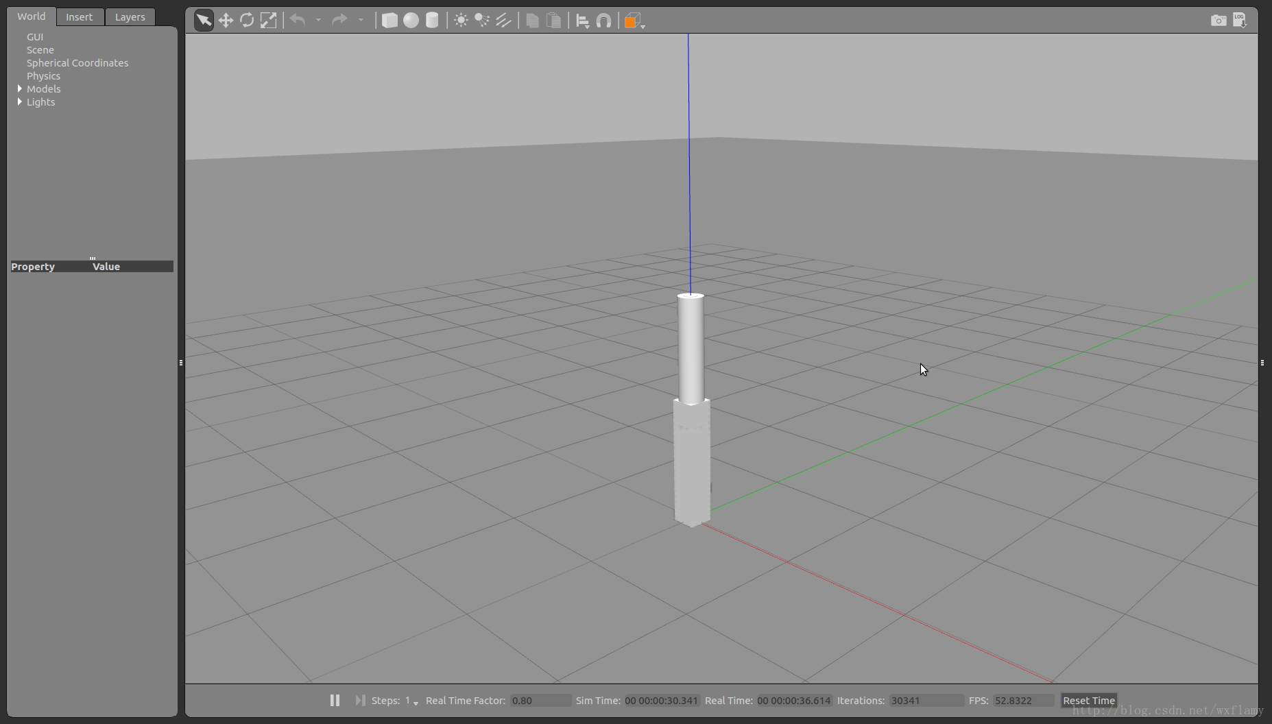
以下命令可以查看机器人相关信息的变化曲线
rosrun rqt_gui rqt_gui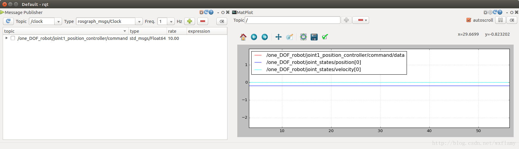
在左侧窗口中可以输入位置命令sin(i/20)/2-0.5,观察变化。其中i表示时间
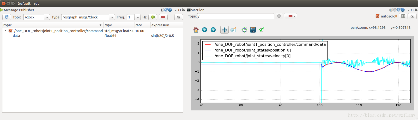
如果发送单个值可以采用命令行的形式,如-0.5:
rostopic pub /one_DOF_robot/joint1_potion_controller/command std_msgs/Float64 "data: -0.5" 速度控制与此类似,速度控制发送控制命令时最好速度控制命令同时发布如下正弦速度命令
#include <ros/ros.h>
#include <std_msgs/Float64.h>
//#include <sensor_msgs/JointState.h>
#include <math.h>
using namespace std;

//displacement limits:
const double x_max=0.0;
const double x_min=-1.0;

int main(int argc, char **argv) {
    ros::init(argc, argv, "sine_commander"); // name of this node will be "minimal_publisher2"
    ros::NodeHandle n; // two lines to create a publisher object that can talk to ROS
    ros::Publisher vel_cmd_publisher = n.advertise<std_msgs::Float64>("/one_DOF_robot/joint1_velocity_controller/command", 1);
    ros::Publisher pos_cmd_publisher = n.advertise<std_msgs::Float64>("/one_DOF_robot/joint1_position_controller/command", 1);
    //std_msgs::JointState js;
    //js.velocity.push_back(0.0);
    //js.position.push_back(0.0);

   std_msgs::Float64 vel_cmd_float64, pos_cmd_float64; //create a variable of type "Float64",

    //input_float.data = 0.0;
   double v_cmd=0.0;
   double x_cmd=0.0;
   double x_amp=0.0;
   double freq,omega,x_mid;
   x_mid = (x_max+x_min)/2.0;
   cout<<"enter displacement amplitude: ";
   cin>>x_amp;
   cout<<"enter freq (in Hz): ";
   cin>>freq;
   omega = freq*2.0*M_PI;
   double phase=0;
   double dt = 0.01;
   ros::Rate sample_rate(1/dt);

    // do work here in infinite loop (desired for this example), but terminate if detect ROS has faulted
    while (ros::ok())
    {
        phase+= omega*dt;
        if (phase>2.0*M_PI) phase-=2.0*M_PI;
        x_cmd = x_amp*sin(phase)+x_mid;
        v_cmd = omega*x_amp*cos(phase);
        vel_cmd_float64.data = v_cmd;
        pos_cmd_float64.data = x_cmd;
        vel_cmd_publisher.publish(vel_cmd_float64); // publish the value--of type Float64--
        pos_cmd_publisher.publish(pos_cmd_float64); // publish the value--of type Float64--
    sample_rate.sleep();
    }
}
力控制
上述机器人模型中加入了一个力传感器,下面我们在此基础上做一些应用。
保持启动位置控制的gazebo环境,运行以下命令
rostopic info ft_sensor_topic可以看到力传感器话题的消息类型为
Type: geometry_msgs/WrenchStamped我们可以在图表中观察到它的信息。如果给他加入一个重物,可以观察到力的变化
roslaunch exmpl_models add_cylinder_weight.launch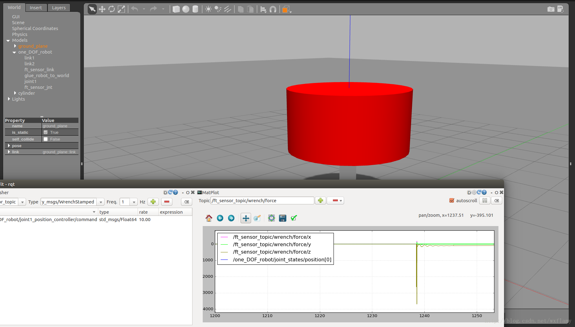
使用阻抗控制器调节关节速度命令可以实现力控制的调节,称为自然导纳控制(natural admittance controller, NAC)
        f_virt = K_virt*(x_attractor-g_link2_pos) + B_virt*(0-g_link2_vel);
        f_net =    g_force_z + f_virt;
        acc_ideal = f_net/M_virt;
        v_ideal+= acc_ideal*dt;
        v_ideal = sat(v_ideal, v_ideal_sat);
        v_cmd_float64.data = v_ideal;

        cmd_publisher.publish(v_cmd_float64); // publish the value--of type Float64--
七自由度的机器人原理一样,都是自然导纳控制,nac。只不过七个自由度需要正逆运动学的计算
关于正逆运动学计算的问题以后再说。
机械臂的轨迹消息
在ROS中,执行关节运动规划的传统方法是将轨迹消息发布给轨迹执行动作服务器。
在URDF描述的机器人模型中,一个机器人模型包含一系列机器人杆件,这些杆件通过关节连接。每一个关节允许一个自由度的运动:旋转或者平移。任何一种运动类型通常都会产生位移。位移命令输入给底层伺服控制器,由控制器驱动力或者力矩达到目标状态。目标状态包括位移、速度、加速度。控制器会比较目标状态与当前状态来计算驱动力,有执行机构执行。
如果目标状态与当前状态相差较大,控制器会产生异常驱动力,导致驱动力饱和,对目标状态的跟踪和收敛效果变差。运动结果会超出预期甚至出现危险。
为了保证机器人能够实现期望的运动,运动命令应该保证能够满足以下约束:
- 机器人不会与环境中的障碍物进行碰撞;
- 关节运动的幅度应该在关节运动最大和最小约束范围内;
- 关节速度应该在驱动器的约束范围内;
- 所需要的驱动力应该在驱动器的约束范围内。
前两条是对路径规划的约束,路径定义了一系列的位姿。后两条是对轨迹的规划,需要在一定时间内完成路径。为了将路径转换成轨迹,必须在每个路径点增加时间,保证最终的速度和力约束能够满足。
一定要避免的情况是给任何一个关节发布阶跃命令,如果一个关节被要求从A点瞬间移动到B点,这种运动物理上根本不会达到,结果也会难以预料。
安全的机器人命令是按频率更新的,所有关节的命令都应该是平滑连续的。
由于是常见的命令,ROS中有这种命令类型的消息:trajectorymsgs/JointTrajectory.
调用
rosmsg show trajectory_msgs/JointTrajectory会看到消息包含的信息
std_msgs/Header header
  uint32 seq
  time stamp
  string frame_id
string[] joint_names
trajectory_msgs/JointTrajectoryPoint[] points
  float64[] positions
  float64[] velocities
  float64[] accelerations
  float64[] effort
  duration time_from_start
由于命令处于关节空间(每个关节的期望状态),所以frame_id没有意义。
大量的轨迹消息是trajectory_msgs/JointTrajectory类型的向量,这种类型包含四个可变长度向量和一个持续时间。轨迹命令可以使用四个中的一个也可以使用全部。常见的只有一个向量的是位置向量。这对于位置反馈的低速运动控制是足够的。此外轨迹命令可能与速度控制器进行通信,更复杂的关节控制器会使用更复杂的消息类型,通常使用的是位置速度类型。
为了命令七自由度的机器人的所有关节的协调运动,例如,从当前姿态开始并以某个期望姿态结束,将会(至少)为N个要访问的N个点中的每一个的位置向量填充命令。 更好的是,这些点在空间上相对接近(即,在连续点规范之间的任何一个关节位移命令中具有相对小的变化)。 或者,可以将较粗略的轨迹传送给轨迹内插器,轨迹内插器将粗略子目标之间的运动分解为精细运动命令流。
理想的情况是,每个点都包括与指定的位移和到达时间一致的关节速度的指定(尽管指定轨迹而没有指定关节速度是合法的)。 或者,一致的速度命令的生成可能留给较低级别的轨迹内插器节点。
每个要访问的联合空间点必须指定一个从起始点开始的时间点。 对于连续点,这些时间规格必须单调递增,并且应与速度规格一致。 用户有责任评估指定的关节位移,关节速度和点到达时间是否都是自洽的,并且可以在机器人的限制范围内实现。
从要访问的每个联合空间点指定的启动时间开始,从轨迹区分一条路径。 如果只指定要实现的姿势序列,则结果将是路径描述。 通过随时间增加空间(路径)信息,结果是一个轨迹(在联合空间中)。
虽然轨迹消息可能是细粒度和冗长的,但发送包含一系列子目标(具有足够的分辨率)的消息更为常见(且实用)。 通过动作服务器插补可以生成细粒度的命令。 example_trajectory包中提供了一个说明性示例。
这个包中定义了一个action消息:TrajAction.action。目标消息是trajectory::JointTrajectory。这个action消息由轨迹客户作为运动目标发送给轨迹动作服务器。
两个说明的节点分别是:example_trajectory_action_client与example_trajectory_action_server。客户计算一个期望的轨迹,在这种情况下由joint1的正弦运动样本组成。 (这可以很容易地扩展到N个关节,但这对于在minimalrobot机器人上进行测试就足够了。)样本是在不规则和相当粗糙的时间间隔内有意采集的。
位置命令(弧度)的值表明起始正弦函数粗略且不规则地被采样。 这是为了说明轨迹信息的一般性,并表明它不需要细粒度。
以下函数实现了将一个粗略的轨迹进行细化的action功能。
//here is where we do the work to act on goal requests
void TrajectoryActionServer::executeCB(const actionlib::SimpleActionServer<example_trajectory::TrajActionAction>::GoalConstPtr& goal) {
    // the class owns the action server, so we can use its member methods here
    // the goal is a pointer, and the action message contains a "trajectory" field;
    trajectory_msgs::JointTrajectory trajectory = goal->trajectory; // goal-> notation is annoying, so copy the important stuff to a shorter named var

    ros::Rate rate_timer(1/dt); //here is a timer, consistent with our chosen time step

    int npts = trajectory.points.size(); // how many poses are contained in the goal request?
    ROS_INFO("received trajectory with %d points",npts); //debug/interpretation output

    int njoints = trajectory.joint_names.size(); // determine how many joints we have...though we really already know, for this example robot
    vector <double> q_prev_jnts; // for extension to multiple joints, create a variable-length array to hold joint commands
    vector <double> q_next_jnts; // we will interpolate between coarse joint commands, from q_prev_jnts to q_next_jnts
    vector <double> q_cmd_jnts;  // will contain interpolated joint command values
    q_prev_jnts.resize(njoints); // these arrays need to be this large to be consistent with dimension of input
    q_next_jnts.resize(njoints);
    q_cmd_jnts.resize(njoints);

    ROS_INFO("trajectory message commands %d joint(s)",njoints);
    double t_final = trajectory.points[npts-1].time_from_start.toSec(); // what is the last value of time_from_start specified?  convert to seconds
    ROS_INFO("t_final = %f",t_final);
    double t_previous = 0.0;
    double t_next = trajectory.points[1].time_from_start.toSec();
    double t_stream=0.0; //start the clock from time 0
    double fraction_of_range=0.0; // this will be a ratio describing fraction of current segment completed
    double q_prev, q_next, q_cmd;
    //start streaming points...interpolate, as needed.
    int ipt_next = 1;
    double t_range = t_next-t_previous;
    if (t_range< min_dt) {
        ROS_WARN("time step invalid in trajectory!");
        as_.setAborted(result_);
    }
    //put the starting joint commands here.  Really, these NEED to be the robot's actual joint commands!
    // this should be tested (and abort goal if not within some tolerance)
    q_prev_jnts = trajectory.points[ipt_next-1].positions;
    q_next_jnts = trajectory.points[ipt_next].positions;
    while (t_stream<t_final) {
        //compute desired pose at current time
        // see if t has stepped across current range, t_previous to t_next
        while (t_stream>t_next) { //find the next time range in the sequence
            ipt_next++;
            t_previous = t_next; //shift this down--former "next" is new "previous" in t_previous< t < t_next
            t_next = trajectory.points[ipt_next].time_from_start.toSec();
            t_range = t_next-t_previous;
            if (t_range< min_dt) {
                ROS_WARN("time step invalid in trajectory!");
                as_.setAborted(result_);
                break;
            }
            q_prev_jnts = trajectory.points[ipt_next-1].positions;  //find bounds for joint commands at previous and next time boundaries
            q_next_jnts = trajectory.points[ipt_next].positions;
        }

        // if here, have valid range t_previous < t_stream < t_next
        //COMMENT OUT THE NEXT LINE TO SEE COARSE TRAJECTORY WITHOUT INTERPOLATION
        fraction_of_range = (t_stream-t_previous)/(t_next-t_previous);

        //interpolate on the joint commands...linearly;  COULD BE BETTER, e.g. with splines
        for (int ijnt = 0;ijnt<njoints;ijnt++) {
           q_cmd_jnts[ijnt] = q_prev_jnts[ijnt] + fraction_of_range*(q_next_jnts[ijnt]-q_prev_jnts[ijnt]); //here is a vector of new joint commands;
        }
         ROS_INFO("t_prev, t_stream, t_next, fraction = %f, %f, %f, %f",t_previous,t_stream,t_next,fraction_of_range);
         ROS_INFO("q_prev, q_cmd, q_next: %f, %f, %f",q_prev_jnts[0],q_cmd_jnts[0],q_next_jnts[0]);
        //command the joints:  this implementation will depend on the specific interface to the robot;
        send_joint_commands_(q_cmd_jnts); // use helper function to encapsulate details of how to talk to the controller;

        rate_timer.sleep();
        t_stream+=dt;
    }
    // output the final point; WATCH OUT HERE...trajectory messages are allowed to list joint commands in any order, as specified in
    // joint_names vector.  Further, it is generally allowed to specify commands for only a subset of joints (as listed in the joint_names vector),
    // with the presumption that all joints not listed should maintain their most recently commanded values.
    // I am shamelessly ignoring all of this, assuming joint commands are always specified for ALL joints, and that these commands are
    // always in the same, fixed order
    // This is a limitation if we want to control subsystems independently--e.g. hands on a steering wheel, vs feet on pedals, each
    // following their own respective algorithms.  For a single robot arm, though, subsystem control is not useful.

    q_cmd_jnts = trajectory.points[npts-1].positions;
    send_joint_commands_(q_cmd_jnts);
    //should populate result with something useful...
         as_.setSucceeded(result_); // tell the client that we were successful acting on the request, and return the "result" message
}