H-Express Library——–timeline
这是母项目 H-Express 中的那个自定义时间轴view,现抽取出来分享给大家,这个自定义view比较简单,作为学习自定义view入门的朋友可不能错过了。
一般可以应用在单号追踪、历史事件记录、任务完成度显示等方面,作为Recyclerview或者listview的item布局即可。
先上图:


左边为H-Express中的效果,右边为原始效果,横向和竖向。
import
AS:
    dependencies {
            compile 'com.qht1003077897.timeline:timelinelibrary:0.1'
    }
EC:
使用eclipse的同学直接到项目的github地址下面timelinelibrary中拷贝出两个类,一个attrs出来,放到自己项目中即可。
使用
    <com.bt.mylibrary.TimeLineMarkerView
        android:id="@+id/time1"
        android:layout_width="150dp"
        android:layout_height="100dp"
        android:paddingTop="20dp"
        app:beginLine="@color/blue_sky"
        app:endLine="@color/blue_sky"
        app:oritation="true"
        app:marker="@drawable/timeline_bg_blue"/>
看完了怎么用下来就该看看源码实现了
timeline的实现很简单,我这里以竖向为例,横向的类似。总结为2点:
- 首先以整个view的正中心然后靠左边界为基准绘制中间的圆,如图。为什么要靠左边呢,因为放在左边界再加上合适的paddingLeft就很容易能控制圆的位置了(同理,横向的靠上边,使用paddingTop控制圆的位置)。
然后以这个圆为基准,再绘制上面的线条和下面的线条。
下面是6个属性,以供xml中进行设置。
<?xml version="1.0" encoding="utf-8"?>
<resources>
    <declare-styleable name="TimeLineMarker">
        <!--圆点大小-->
        <attr name="markerSize" format="dimension" />
        <!--圆点颜色或者图片-->
        <attr name="marker" format="color|reference" />
        <!--上面/左边线段颜色或者图片-->
        <attr name="beginLine" format="color|reference" />
        <!--下面/右边线段颜色或者图片-->
        <attr name="endLine" format="color|reference" />
        <!--线段粗细-->
        <attr name="lineSize" format="dimension" />
        <!--横向还是竖向-->
        <attr name="oritation" format="boolean" />
    </declare-styleable>
</resources>
很简单的 onMeasure() 方法,如果你的自定义 view 没有什么特殊需求,直接把这个拿去用,通用版。
@Override
    protected void onMeasure(int widthMeasureSpec, int heightMeasureSpec) {
        super.onMeasure(widthMeasureSpec, heightMeasureSpec);

        int widthSpecSize= MeasureSpec.getSize(widthMeasureSpec);
        int heightSpecSize= MeasureSpec.getSize(heightMeasureSpec);
        int widthSpecMode= MeasureSpec.getMode(widthMeasureSpec);
        int heightSpecMode= MeasureSpec.getMode(heightMeasureSpec);
        //判断横向还是竖向,true为横向
        if(oritation){
            if(widthSpecMode== MeasureSpec.AT_MOST && heightSpecMode== MeasureSpec.AT_MOST){
                setMeasuredDimension(120,80);//针对wrap情况做处理
            }else if(widthSpecMode== MeasureSpec.AT_MOST ){
                setMeasuredDimension(120,heightSpecSize);
            }else if(heightSpecMode== MeasureSpec.AT_MOST ){
                setMeasuredDimension(widthSpecSize,80);
            }
        }else{
            if(widthSpecMode== MeasureSpec.AT_MOST && heightSpecMode== MeasureSpec.AT_MOST){
                setMeasuredDimension(80,120);//针对wrap情况做处理
            }else if(widthSpecMode== MeasureSpec.AT_MOST ){
                setMeasuredDimension(80,heightSpecSize);
            }else if(heightSpecMode== MeasureSpec.AT_MOST ){
                setMeasuredDimension(widthSpecSize,120);
            }
        }
    }
因为我们使用的元素为3个 drawable,是现成的 view,所以已经不需要在 ondraw()方法中进行绘制了,而更多的是调整每个 drawable 的位置,所以下面的方法写在 onSizeChanged() 中更合适。
 @Override
    protected void onDraw(Canvas canvas) {
        super.onDraw(canvas);
        initDrawableSize();
        if (mBeginLine != null) {
            mBeginLine.draw(canvas);
        }
        if (mEndLine != null) {
            mEndLine.draw(canvas);
        }
        if (mMarkerDrawable != null) {
            mMarkerDrawable.draw(canvas);
        }
    }
主要看一下 initDrawableSize() 方法:
 private void initDrawableSize() {
        int pLeft=getPaddingLeft();
        int pRight=getPaddingRight();
        int pTop=getPaddingTop();
        int pBottom=getPaddingBottom();
        int width=getWidth();
        int height=getHeight();
        int cWidth=width-pLeft-pRight;
        int cHeight=height-pTop-pBottom;
        Rect bounds;
        int mMarkerSizepx=ResourceUtil.dip2px(getContext(),mMarkerSize);
        int mLineSizepx=ResourceUtil.dip2px(getContext(),mLineSize);
        //以竖向为例
if(mMarkerDrawable!=null){
                int marksize= Math.min(Math.min(cWidth,cHeight), mMarkerSizepx);
                mMarkerDrawable.setBounds(pLeft,pTop+height/2-marksize/2,pLeft+marksize,pTop+height/2-marksize/2+marksize);
                bounds=mMarkerDrawable.getBounds();
            }else{
                bounds=new Rect(pLeft+mLineSizepx/2,pTop+height/2,pLeft+mLineSizepx/2,pTop+height/2);
            }
            int halfLine=mLineSizepx >> 1;
            int lineLeft=bounds.centerX()-halfLine;
            if(mBeginLine!=null){       mBeginLine.setBounds(lineLeft,0,lineLeft+mLineSizepx,bounds.top);
            }
            if(mEndLine!=null){
mEndLine.setBounds(lineLeft,bounds.bottom,lineLeft+mLineSizepx,height);
  }
}
先了解一下 setBounds() 方法:

这句话的意思是:为Drawable 指定一个矩形区域,在onDraw() 方法被调用时使用。
这个矩形区域参数要求:矩形左边距view左边界的距离,矩形上边距view上边界的距离,矩形右边距view左边界的距离,矩形下边距view上边界的距离。
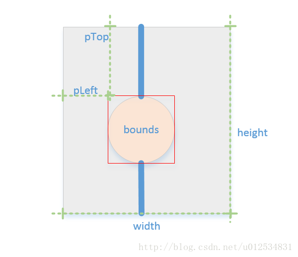
首先设置 mMarkerDrawable 的 bounds,左边的距离为pleft,上下为中心位置,确定了这个 bounds 为基准位置之后,再去绘制上下线条。
如果 mMarkerDrawable 为空,即在 xml 中不要这个圆,那么我们此处是将它看做一个点,一个左边的距离为pleft,上下为中心位置的点,作为我们的基准点,然后再去绘制上下线条,最终绘制出来的即为一条线段。
对于上下线的绘制很简单,这里以上线条为例,线条上端紧挨view的顶端,下端紧挨这个bounds的顶部,线条的长度为 bounds 的顶端距离上边界的距离。线条长度和 bounds 挂上钩之后,我们如果在 xml 中设置 paddingTop ,则 bounds.top 变大,线条长度变长,圆相应的往下移动。bounds.top= pTop +(height/2-mMarkerSize/2)。
 //下来提供几个方法。以供代码动态设置
    public void setMarkerSize(int markerSize) {
        if (this.mMarkerSize != markerSize) {
            mMarkerSize = markerSize;
            invalidate();
        }
    }

    public void setBeginLine(Drawable beginLine) {
        if (this.mBeginLine != beginLine) {
            this.mBeginLine = beginLine;
            if (mBeginLine != null) {
                mBeginLine.setCallback(this);
            }
            invalidate();
        }
    }
    ·············
源码github地址:
https://github.com/qht1003077897/timeline
我的QQ: 1003077897
我的csdn:http://blog.csdn.net/u012534831
欢迎交流。