本文详细绍了基于STM32F107VC的金牛开发板的FreeRTOS v9.0.0 的移植过程。
**IDE环境为: MDK v5.23;
硬件环境:基于STM32F107VC的金牛开发板;
所用固件库版本号是STM32F10X_StdPeriph_Lib_V3.5.0**
下载工具用的是开发板自带的D版的Jlink。
一、工程模板的建立:
(参考:http://blog.csdn.net/u014563989/article/details/51000138)
STM32工程模板用野火M3工程模板作为基础,在此之上做一些更改:
下载地址:https://pan.baidu.com/share/link?shareid=4218340238&uk=1194094710&fid=909646254491523

然后改一下文件名为STM32F107_FreeRTOS_v9.0.0:
进去之后看到:
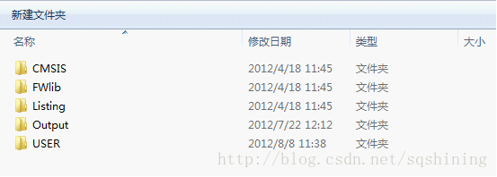
其结构内容如下:
CMSIS:微控制器软件接口标准库相关文件(详细解释请参考:http://blog.chinaunix.net/uid-27710926-id-4231846.html);
FWlib:固件库(版本号为v3.5.0);
Listing:编译链接信息列表;
Output:编译中间文件和bin档(或hex档)。
USER:工程模板和用户源代码。
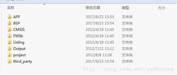
下面对它的目录结构做如下修改:
1、把USER文件夹改为project,意为此处放置工程文件,而不是放源代码;
2、增加BSP文件夹,作为板卡支持包目录,放置与开发板特定配置下的相关源代码;
3、增加APP文件夹,作为应用软件源代码目录;
4、增加third_party文件夹,作为第三方库管理目录,放置第三方库源码。
改后目录结构如图:
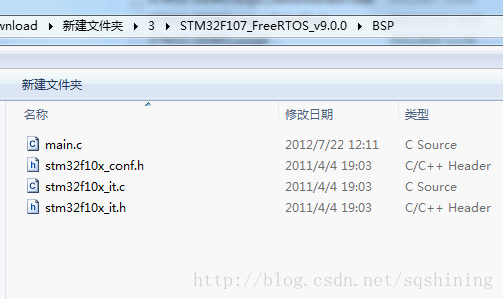
接下来,把相应文件做调整,并修改工名:
把project目录下的main.c、stm32f10x_conf.h、stm32f10x_it.h、stm32f10x_it.h四个文件剪切到BSP目录下:
project目录下只留下扩展名为.uvopt和.ubproj的两个文件,其他的都删除:
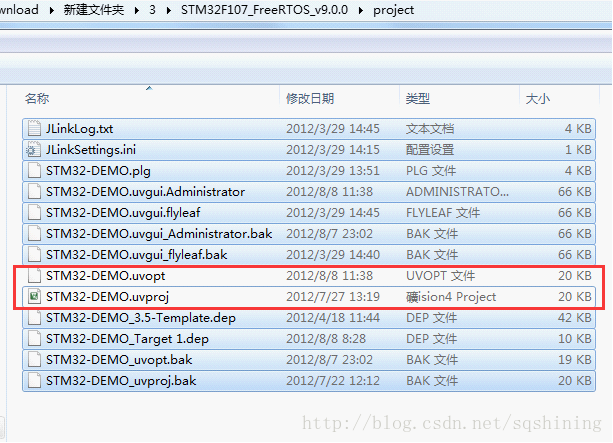
然后把两个文件都改名为FreeRTOS_v9.0.0,如图:
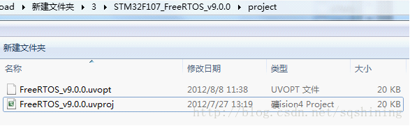
接下来双击FreeRTOS_v9.0.0.uvproj文件,打开工程:
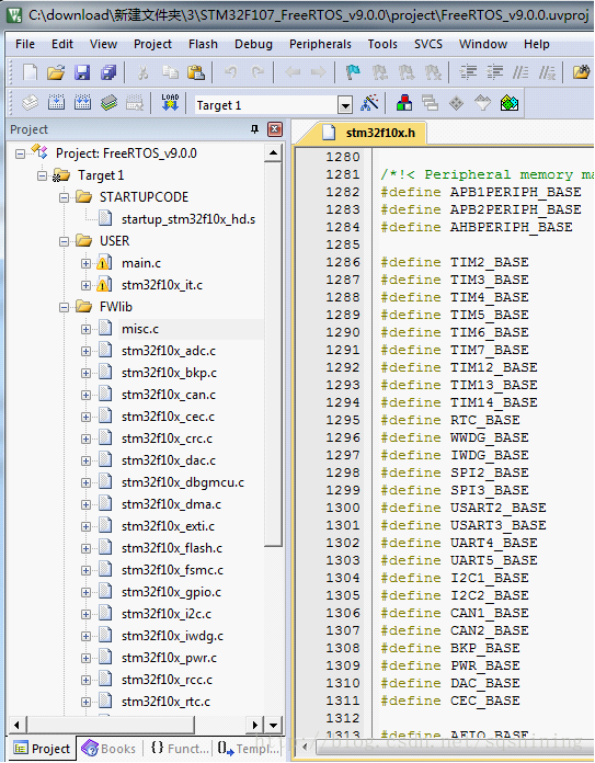
点击品字形图标:
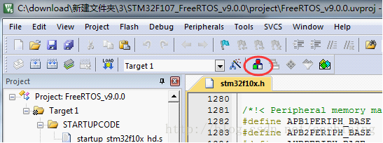
看到如下对话框:
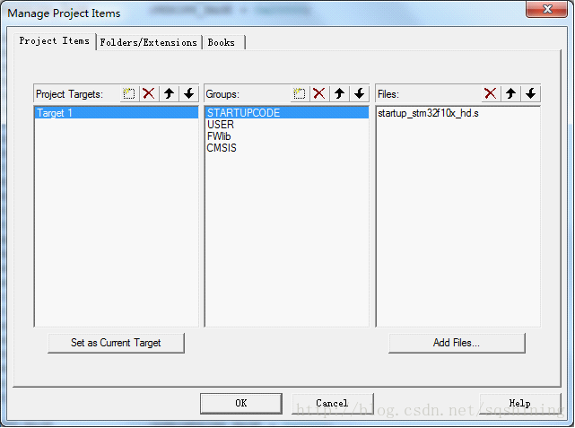
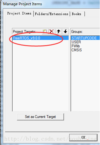
然后双击左边那个Target1,改名为FreeRTOS_v9.0.0:
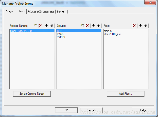
中间的列表删掉STARTUPCODE,双击修改USER为BSP,并在右边的列表中的main.c和stm32f10x_it.c文件删除,重新加入(两个文件已经由前面的步骤放置在了电脑的BSP目录下):
然后,把金牛板的启动文件STM32F10x.s修改一下放置在BSP目录下,该文件内容如下:
;/*****************************************************************************/
;/* STM32F10x.s: Startup file for ST STM32F10x device series */
;/*****************************************************************************/
;/* <<< Use Configuration Wizard in Context Menu >>> */
;/*****************************************************************************/
;/* This file is part of the uVision/ARM development tools. */
;/* Copyright (c) 2005-2007 Keil Software. All rights reserved. */
;/* This software may only be used under the terms of a valid, current, */
;/* end user licence from KEIL for a compatible version of KEIL software */
;/* development tools. Nothing else gives you the right to use this software. */
;/*****************************************************************************/
;// <h> Stack Configuration
;// <o> Stack Size (in Bytes) <0x0-0xFFFFFFFF:8>
;// </h>
Stack_Size EQU 0x00000400
AREA STACK, NOINIT, READWRITE, ALIGN=3
Stack_Mem SPACE Stack_Size
__initial_sp
;// <h> Heap Configuration
;// <o> Heap Size (in Bytes) <0x0-0xFFFFFFFF:8>
;// </h>
Heap_Size EQU 0x00000200
AREA HEAP, NOINIT, READWRITE, ALIGN=3
__heap_base
Heap_Mem SPACE Heap_Size
__heap_limit
;IMPORT xPortPendSVHandler
;IMPORT xPortSysTickHandler
;IMPORT vPortSVCHandler
;IMPORT vUARTInterruptHandler
;IMPORT TIM4_IRQHandler
;IMPORT vTimer2IntHandler
PRESERVE8
THUMB
; Vector Table Mapped to Address 0 at Reset
AREA RESET, DATA, READONLY
EXPORT __Vectors
EXPORT __Vectors_End
EXPORT __Vectors_Size
__Vectors DCD __initial_sp ; Top of Stack
DCD Reset_Handler ; Reset Handler
DCD NMI_Handler ; NMI Handler
DCD HardFault_Handler ; Hard Fault Handler
DCD MemManage_Handler ; MPU Fault Handler
DCD BusFault_Handler ; Bus Fault Handler
DCD UsageFault_Handler ; Usage Fault Handler
DCD 0 ; Reserved
DCD 0 ; Reserved
DCD 0 ; Reserved
DCD 0 ; Reserved
DCD 0 ;vPortSVCHandler ; SVCall Handler
DCD DebugMon_Handler ; Debug Monitor Handler
DCD 0 ; Reserved
DCD 0 ;xPortPendSVHandler ; PendSV Handler
DCD 0 ;xPortSysTickHandler ; SysTick Handler
; External Interrupts
DCD WWDG_IRQHandler ; Window Watchdog
DCD PVD_IRQHandler ; PVD through EXTI Line detect
DCD TAMPER_IRQHandler ; Tamper
DCD RTC_IRQHandler ; RTC
DCD FLASH_IRQHandler ; Flash
DCD RCC_IRQHandler ; RCC
DCD EXTI0_IRQHandler ; EXTI Line 0
DCD EXTI1_IRQHandler ; EXTI Line 1
DCD EXTI2_IRQHandler ; EXTI Line 2
DCD EXTI3_IRQHandler ; EXTI Line 3
DCD EXTI4_IRQHandler ; EXTI Line 4
DCD DMAChannel1_IRQHandler ; DMA Channel 1
DCD DMAChannel2_IRQHandler ; DMA Channel 2
DCD DMAChannel3_IRQHandler ; DMA Channel 3
DCD DMAChannel4_IRQHandler ; DMA Channel 4
DCD DMAChannel5_IRQHandler ; DMA Channel 5
DCD DMAChannel6_IRQHandler ; DMA Channel 6
DCD DMAChannel7_IRQHandler ; DMA Channel 7
DCD ADC_IRQHandler ; ADC
DCD USB_HP_CAN_TX_IRQHandler ; USB High Priority or CAN TX
DCD USB_LP_CAN_RX0_IRQHandler ; USB Low Priority or CAN RX0
DCD CAN_RX1_IRQHandler ; CAN RX1
DCD CAN_SCE_IRQHandler ; CAN SCE
DCD EXTI9_5_IRQHandler ; EXTI Line 9..5
DCD TIM1_BRK_IRQHandler ; TIM1 Break
DCD TIM1_UP_IRQHandler ; TIM1 Update
DCD TIM1_TRG_COM_IRQHandler ; TIM1 Trigger and Commutation
DCD TIM1_CC_IRQHandler ; TIM1 Capture Compare
;
DCD 0 ;vTimer2IntHandler ; TIM2
DCD TIM3_IRQHandler ; TIM3
DCD 0 ;TIM4_IRQHandler ; TIM4
DCD I2C1_EV_IRQHandler ; I2C1 Event
DCD I2C1_ER_IRQHandler ; I2C1 Error
DCD I2C2_EV_IRQHandler ; I2C2 Event
DCD I2C2_ER_IRQHandler ; I2C2 Error
DCD SPI1_IRQHandler ; SPI1
DCD SPI2_IRQHandler ; SPI2
DCD 0 ;vUARTInterruptHandler ; USART1
DCD USART2_IRQHandler ; USART2
DCD USART3_IRQHandler ; USART3
DCD EXTI15_10_IRQHandler ; EXTI Line 15..10
DCD RTCAlarm_IRQHandler ; RTC Alarm through EXTI Line
DCD USBWakeUp_IRQHandler ; USB Wakeup from suspend
;-------------------added @2017.08.1
DCD 0 ; Reserved
DCD 0 ; Reserved
DCD 0 ; Reserved
DCD 0 ; Reserved
DCD 0 ; Reserved
DCD 0 ; Reserved
DCD 0 ; Reserved
DCD TIM5_IRQHandler ; TIM5
DCD SPI3_IRQHandler ; SPI3
DCD UART4_IRQHandler ; UART4
DCD UART5_IRQHandler ; UART5
DCD TIM6_IRQHandler ; TIM6
DCD TIM7_IRQHandler ; TIM7
DCD DMA2_Channel1_IRQHandler ; DMA2 Channel1
DCD DMA2_Channel2_IRQHandler ; DMA2 Channel2
DCD DMA2_Channel3_IRQHandler ; DMA2 Channel3
DCD DMA2_Channel4_IRQHandler ; DMA2 Channel4
DCD DMA2_Channel5_IRQHandler ; DMA2 Channel5
DCD 0 ;ETH_IRQHandler ; Ethernet
DCD ETH_WKUP_IRQHandler ; Ethernet Wakeup through EXTI line
DCD CAN2_TX_IRQHandler ; CAN2 TX
DCD CAN2_RX0_IRQHandler ; CAN2 RX0
DCD CAN2_RX1_IRQHandler ; CAN2 RX1
DCD CAN2_SCE_IRQHandler ; CAN2 SCE
DCD OTG_FS_IRQHandler ; USB OTG FS
__Vectors_End
__Vectors_Size EQU __Vectors_End - __Vectors
AREA |.text|, CODE, READONLY
; Reset handler
Reset_Handler PROC
EXPORT Reset_Handler [WEAK]
IMPORT SystemInit
IMPORT __main
LDR R0, =SystemInit
BLX R0
LDR R0, =__main
BX R0
ENDP
; Dummy Exception Handlers (infinite loops which can be modified)
NMI_Handler PROC
EXPORT NMI_Handler [WEAK]
B .
ENDP
HardFault_Handler\
PROC
EXPORT HardFault_Handler [WEAK]
B .
ENDP
MemManage_Handler\
PROC
EXPORT MemManage_Handler [WEAK]
B .
ENDP
BusFault_Handler\
PROC
EXPORT BusFault_Handler [WEAK]
B .
ENDP
UsageFault_Handler\
PROC
EXPORT UsageFault_Handler [WEAK]
B .
ENDP
SVC_Handler PROC
EXPORT SVC_Handler [WEAK]
B .
ENDP
DebugMon_Handler\
PROC
EXPORT DebugMon_Handler [WEAK]
B .
ENDP
PendSV_Handler PROC
EXPORT PendSV_Handler [WEAK]
B .
ENDP
SysTick_Handler PROC
EXPORT SysTick_Handler [WEAK]
B .
ENDP
Default_Handler PROC
EXPORT WWDG_IRQHandler [WEAK]
EXPORT PVD_IRQHandler [WEAK]
EXPORT TAMPER_IRQHandler [WEAK]
EXPORT RTC_IRQHandler [WEAK]
EXPORT FLASH_IRQHandler [WEAK]
EXPORT RCC_IRQHandler [WEAK]
EXPORT EXTI0_IRQHandler [WEAK]
EXPORT EXTI1_IRQHandler [WEAK]
EXPORT EXTI2_IRQHandler [WEAK]
EXPORT EXTI3_IRQHandler [WEAK]
EXPORT EXTI4_IRQHandler [WEAK]
EXPORT DMAChannel1_IRQHandler [WEAK]
EXPORT DMAChannel2_IRQHandler [WEAK]
EXPORT DMAChannel3_IRQHandler [WEAK]
EXPORT DMAChannel4_IRQHandler [WEAK]
EXPORT DMAChannel5_IRQHandler [WEAK]
EXPORT DMAChannel6_IRQHandler [WEAK]
EXPORT DMAChannel7_IRQHandler [WEAK]
EXPORT ADC_IRQHandler [WEAK]
EXPORT USB_HP_CAN_TX_IRQHandler [WEAK]
EXPORT USB_LP_CAN_RX0_IRQHandler [WEAK]
EXPORT CAN_RX1_IRQHandler [WEAK]
EXPORT CAN_SCE_IRQHandler [WEAK]
EXPORT EXTI9_5_IRQHandler [WEAK]
EXPORT TIM1_BRK_IRQHandler [WEAK]
EXPORT TIM1_UP_IRQHandler [WEAK]
EXPORT TIM1_TRG_COM_IRQHandler [WEAK]
EXPORT TIM1_CC_IRQHandler [WEAK]
EXPORT TIM2_IRQHandler [WEAK]
EXPORT TIM3_IRQHandler [WEAK]
;EXPORT TIM4_IRQHandler [WEAK]
EXPORT I2C1_EV_IRQHandler [WEAK]
EXPORT I2C1_ER_IRQHandler [WEAK]
EXPORT I2C2_EV_IRQHandler [WEAK]
EXPORT I2C2_ER_IRQHandler [WEAK]
EXPORT SPI1_IRQHandler [WEAK]
EXPORT SPI2_IRQHandler [WEAK]
EXPORT USART1_IRQHandler [WEAK]
EXPORT USART2_IRQHandler [WEAK]
EXPORT USART3_IRQHandler [WEAK]
EXPORT EXTI15_10_IRQHandler [WEAK]
EXPORT RTCAlarm_IRQHandler [WEAK]
EXPORT USBWakeUp_IRQHandler [WEAK]
;-------------added @2017.08.13-----------------------------
EXPORT TIM5_IRQHandler [WEAK]
EXPORT SPI3_IRQHandler [WEAK]
EXPORT UART4_IRQHandler [WEAK]
EXPORT UART5_IRQHandler [WEAK]
EXPORT TIM6_IRQHandler [WEAK]
EXPORT TIM7_IRQHandler [WEAK]
EXPORT DMA2_Channel1_IRQHandler [WEAK]
EXPORT DMA2_Channel2_IRQHandler [WEAK]
EXPORT DMA2_Channel3_IRQHandler [WEAK]
EXPORT DMA2_Channel4_IRQHandler [WEAK]
EXPORT DMA2_Channel5_IRQHandler [WEAK]
EXPORT ETH_IRQHandler [WEAK]
EXPORT ETH_WKUP_IRQHandler [WEAK]
EXPORT CAN2_TX_IRQHandler [WEAK]
EXPORT CAN2_RX0_IRQHandler [WEAK]
EXPORT CAN2_RX1_IRQHandler [WEAK]
EXPORT CAN2_SCE_IRQHandler [WEAK]
EXPORT OTG_FS_IRQHandler [WEAK]
WWDG_IRQHandler
PVD_IRQHandler
TAMPER_IRQHandler
RTC_IRQHandler
FLASH_IRQHandler
RCC_IRQHandler
EXTI0_IRQHandler
EXTI1_IRQHandler
EXTI2_IRQHandler
EXTI3_IRQHandler
EXTI4_IRQHandler
DMAChannel1_IRQHandler
DMAChannel2_IRQHandler
DMAChannel3_IRQHandler
DMAChannel4_IRQHandler
DMAChannel5_IRQHandler
DMAChannel6_IRQHandler
DMAChannel7_IRQHandler
ADC_IRQHandler
USB_HP_CAN_TX_IRQHandler
USB_LP_CAN_RX0_IRQHandler
CAN_RX1_IRQHandler
CAN_SCE_IRQHandler
EXTI9_5_IRQHandler
TIM1_BRK_IRQHandler
TIM1_UP_IRQHandler
TIM1_TRG_COM_IRQHandler
TIM1_CC_IRQHandler
TIM2_IRQHandler
TIM3_IRQHandler
;TIM4_IRQHandler
I2C1_EV_IRQHandler
I2C1_ER_IRQHandler
I2C2_EV_IRQHandler
I2C2_ER_IRQHandler
SPI1_IRQHandler
SPI2_IRQHandler
USART1_IRQHandler
USART2_IRQHandler
USART3_IRQHandler
EXTI15_10_IRQHandler
RTCAlarm_IRQHandler
USBWakeUp_IRQHandler
;---------added @2017.08.13--------------------------
TIM5_IRQHandler
SPI3_IRQHandler
UART4_IRQHandler
UART5_IRQHandler
TIM6_IRQHandler
TIM7_IRQHandler
DMA2_Channel1_IRQHandler
DMA2_Channel2_IRQHandler
DMA2_Channel3_IRQHandler
DMA2_Channel4_IRQHandler
DMA2_Channel5_IRQHandler
ETH_IRQHandler
ETH_WKUP_IRQHandler
CAN2_TX_IRQHandler
CAN2_RX0_IRQHandler
CAN2_RX1_IRQHandler
CAN2_SCE_IRQHandler
OTG_FS_IRQHandler
B .
ENDP
ALIGN
; User Initial Stack & Heap
IF :DEF:__MICROLIB
EXPORT __initial_sp
EXPORT __heap_base
EXPORT __heap_limit
ELSE
IMPORT __use_two_region_memory
EXPORT __user_initial_stackheap
__user_initial_stackheap
LDR R0, = Heap_Mem
LDR R1, =(Stack_Mem + Stack_Size)
LDR R2, = (Heap_Mem + Heap_Size)
LDR R3, = Stack_Mem
BX LR
ALIGN
ENDIF
END
该文件会在以后的使用中,为启用某些中断或者修改堆栈设置做修改,暂且如此。
然后把该文件加入工程中,放置在BSP管理项中:

此文件代替了原野火模板中的startup_stm32f10x_hd.s启动文件。
并且,查询资料可知STM32F107VC这款芯片属于cl版本,因此,需要cl版的启动文件。
金牛版的stm32F10x.s就是这个版本的。
并且,原野火模板目标芯片是STM32F103VE,跟我的板子不匹配,需要修改。
另外,在编译配置中需要修改全局宏定义以跟CL版相匹配。
点击魔法棒的那个图标(目标选项),做如下修改:
在Device选项卡里面选STM32F107VC:

在Target选项卡中选择Use MicroLIB

在C/C++选项卡里面的
Proprecessor Symbols设置项的Define栏,修改STM32F10X_HD为STM32F10X_CL:

然后就是修改include搜索目录:
点击Include Paths设置项右边的省略号按钮看到:

双击USER,修改为BSP。
然后修改一下编译输出文件名和相关设置,点击Output选项卡,设置如下:

修改完之后,编译一下,通过,OK。
接下来,用金牛版的跑马灯的代码验证一下能否正让开发板常工作。
修改整个main.c文件如下:
/******************** (C) COPYRIGHT 2012 WildFire Team **************************
 * ÎļþÃû  £ºmain.c
 * ÃèÊö    £ºÓÃ3.5.0°æ±¾½¨µÄ¹¤³ÌÄ£°å¡£
 * ʵÑéƽ̨£ºÒ°»ðSTM32¿ª·¢°å
 * ¿â°æ±¾  £ºST3.5.0
 *
 * ×÷Õß    £ºwildfire team
 * ÂÛ̳    £ºhttp://www.amobbs.com/forum-1008-1.html
 * ÌÔ±¦    £ºhttp://firestm32.taobao.com
**********************************************************************************/
#include "stm32f10x.h"


void GPIO_Configuration(void)
{
    GPIO_InitTypeDef GPIO_InitStructure;

    /* Configure IO connected to LD1, LD2, LD3 and LD4 leds *********************/
    GPIO_InitStructure.GPIO_Pin = GPIO_Pin_2 | GPIO_Pin_3 | GPIO_Pin_4 | GPIO_Pin_7;
    GPIO_InitStructure.GPIO_Mode = GPIO_Mode_Out_PP;
    GPIO_InitStructure.GPIO_Speed = GPIO_Speed_50MHz;
    GPIO_Init(GPIOD, &GPIO_InitStructure);
}

//??????
void NVIC_Configuration(void)
{
    /* Configure the NVIC Preemption Priority Bits */
    NVIC_PriorityGroupConfig(NVIC_PriorityGroup_0);

    #ifdef  VECT_TAB_RAM
      /* Set the Vector Table base location at 0x20000000 */
      NVIC_SetVectorTable(NVIC_VectTab_RAM, 0x0);
    #else  /* VECT_TAB_FLASH  */
      /* Set the Vector Table base location at 0x08000000 */
      NVIC_SetVectorTable(NVIC_VectTab_FLASH, 0x0);
    #endif
}


void RCC_Configuration(void)
{
    SystemInit();
    RCC_APB2PeriphClockCmd(RCC_APB2Periph_USART1 | RCC_APB2Periph_GPIOA
                           |RCC_APB2Periph_GPIOB | RCC_APB2Periph_GPIOC
                           |RCC_APB2Periph_GPIOD | RCC_APB2Periph_GPIOE
                           |RCC_APB2Periph_ADC1  | RCC_APB2Periph_AFIO
                           |RCC_APB2Periph_SPI1, ENABLE );
  // RCC_APB2PeriphClockCmd(RCC_APB2Periph_ALL ,ENABLE );
     RCC_APB1PeriphClockCmd(RCC_APB1Periph_TIM4
                           |RCC_APB1Periph_USART3|RCC_APB1Periph_TIM2
                           , ENABLE );
     RCC_AHBPeriphClockCmd(RCC_AHBPeriph_DMA1, ENABLE);
}


void Init_All_Periph(void)
{
    RCC_Configuration();
    GPIO_Configuration();
    NVIC_Configuration();
}

void Delay(vu32 nCount)
{
  for(; nCount != 0; nCount--);
}

int main(void)
{
    Init_All_Periph();
    while(1)
    {
        /* Turn on LD1 */
        GPIO_SetBits(GPIOD, GPIO_Pin_2);
        /* Insert delay */
        Delay(0xAFFFF);

        /* Turn on LD2 and LD3 */
        GPIO_SetBits(GPIOD, GPIO_Pin_3 | GPIO_Pin_4);
        /* Turn off LD1 */
        GPIO_ResetBits(GPIOD, GPIO_Pin_2);
        /* Insert delay */
        Delay(0xAFFFF);

        /* Turn on LD4 */
        GPIO_SetBits(GPIOD, GPIO_Pin_7);
        /* Turn off LD2 and LD3 */
        GPIO_ResetBits(GPIOD, GPIO_Pin_4 | GPIO_Pin_3);
        /* Insert delay */
        Delay(0xAFFFF);

        /* Turn off LD4 */
        GPIO_ResetBits(GPIOD, GPIO_Pin_7);
    }
}

/******************* (C) COPYRIGHT 2012 WildFire Team *****END OF FILE************/
ok,已经编译出来hex可执行文件啦。
用Jlink把hex档烧到开发板上,然后重新上电,跑马灯炮起来了!
为STM32F107芯片的金牛开发板建立原始模板完成了!
以上作为一个版本,源代码下载地址:
STM32F107_FreeRTOS_v9.0.0_V3.5.0固件库原始模板.rar
二、移植FreeRTOS v9.0.0
1、操作系统基础性移植
参考文章:
1、http://blog.csdn.net/ZCShouCSDN/article/details/54667930
2、http://www.cnblogs.com/foxclever/p/5784326.html
3、https://andyhuzhill.github.io/freertos/2013/07/30/freertostransplant
4、http://blog.csdn.net/zhzht19861011/article/details/50134883
FreeRTOS最新版目前为v9.0.0,下载地址:https://sourceforge.net/projects/freertos/files/latest/download?source=files
下载后,解压看到:

我们所需要的源码在FreeRTOS\Source目录下:

把整个文件夹复制一份到我们工程根目录下,并更名为FreeRTOS:

在IDE工程里对FreeRTOS_v9.0.0右击添加两个组一个命名为FreeRTOS/Source,另一个命名为FreeRTOS/Ports

在FreeRTOS/Source组中添加刚复制过来的FreeRTOS源代码目录下的croutine.c、event_groups.c、list.c、queue.c、tasks.c这五个文件:

在 组中加入port.c和heap_4.c(为什么用heap_4.c可以参考本部分的第2篇参考文章)这两个文件,它们所在的路径为:
port在FreeRTOS\portable\RVDS\ARM_CM3下;
heap_4.c在FreeRTOS\portable\MemMang下。

接下来,需要修改include的路径:
如上述修改include路径一样,点魔法棒,选c/c++选项卡,加入
FreeRTOS\include
FreeRTOS\portable\RVDS\ARM_CM3
这两个目录:

至此,FreeRTOS主要部分已经完成,但是此时编译的话,会出错,提示缺少FreeRTOSConfig.h这个文件,这个文件在哪里呢?在FreeRTOS官方源代码的各个Demo中。
由于本文使用的芯片是STM32F107VC,所以,它在官方源代码的FreeRTOSv9.0.0\FreeRTOS\Demo\CORTEX_STM32F107_GCC_Rowley目录中:

跟FreeRTOS配置相关的文件还包括STM32F10x.s、timertest.c。
把这三个文件复制到我们BSP目录下:

还要修改一下timertest.c里面的内容:
注释掉:
#include "stm32f10x_lib.h"
#include "stm32f10x_map.h"
这两行。
把147行的TIM2_IRQChannel改为TIM2_IRQn,不然编译会出错。因为固件库的命名跟以前不一样了。
改后这个timertest.c完整源代码如下:
/*
    FreeRTOS V9.0.0 - Copyright (C) 2016 Real Time Engineers Ltd.
    All rights reserved

    VISIT http://www.FreeRTOS.org TO ENSURE YOU ARE USING THE LATEST VERSION.

    This file is part of the FreeRTOS distribution.

    FreeRTOS is free software; you can redistribute it and/or modify it under
    the terms of the GNU General Public License (version 2) as published by the
    Free Software Foundation >>>> AND MODIFIED BY <<<< the FreeRTOS exception.

    ***************************************************************************
    >>!   NOTE: The modification to the GPL is included to allow you to     !<<
    >>!   distribute a combined work that includes FreeRTOS without being   !<<
    >>!   obliged to provide the source code for proprietary components     !<<
    >>!   outside of the FreeRTOS kernel.                                   !<<
    ***************************************************************************

    FreeRTOS is distributed in the hope that it will be useful, but WITHOUT ANY
    WARRANTY; without even the implied warranty of MERCHANTABILITY or FITNESS
    FOR A PARTICULAR PURPOSE.  Full license text is available on the following
    link: http://www.freertos.org/a00114.html

    ***************************************************************************
     *                                                                       *
     *    FreeRTOS provides completely free yet professionally developed,    *
     *    robust, strictly quality controlled, supported, and cross          *
     *    platform software that is more than just the market leader, it     *
     *    is the industry's de facto standard.                               *
     *                                                                       *
     *    Help yourself get started quickly while simultaneously helping     *
     *    to support the FreeRTOS project by purchasing a FreeRTOS           *
     *    tutorial book, reference manual, or both:                          *
     *    http://www.FreeRTOS.org/Documentation                              *
     *                                                                       *
    ***************************************************************************

    http://www.FreeRTOS.org/FAQHelp.html - Having a problem?  Start by reading
    the FAQ page "My application does not run, what could be wrong?".  Have you
    defined configASSERT()?

    http://www.FreeRTOS.org/support - In return for receiving this top quality
    embedded software for free we request you assist our global community by
    participating in the support forum.

    http://www.FreeRTOS.org/training - Investing in training allows your team to
    be as productive as possible as early as possible.  Now you can receive
    FreeRTOS training directly from Richard Barry, CEO of Real Time Engineers
    Ltd, and the world's leading authority on the world's leading RTOS.

    http://www.FreeRTOS.org/plus - A selection of FreeRTOS ecosystem products,
    including FreeRTOS+Trace - an indispensable productivity tool, a DOS
    compatible FAT file system, and our tiny thread aware UDP/IP stack.

    http://www.FreeRTOS.org/labs - Where new FreeRTOS products go to incubate.
    Come and try FreeRTOS+TCP, our new open source TCP/IP stack for FreeRTOS.

    http://www.OpenRTOS.com - Real Time Engineers ltd. license FreeRTOS to High
    Integrity Systems ltd. to sell under the OpenRTOS brand.  Low cost OpenRTOS
    licenses offer ticketed support, indemnification and commercial middleware.

    http://www.SafeRTOS.com - High Integrity Systems also provide a safety
    engineered and independently SIL3 certified version for use in safety and
    mission critical applications that require provable dependability.

    1 tab == 4 spaces!
*/

/* High speed timer test as described in main.c. */

/* Scheduler includes. */
#include "FreeRTOS.h"

/* Library includes. */
//#include "stm32f10x_lib.h"
#include "stm32f10x_tim.h"
//#include "stm32f10x_map.h"

/* The set frequency of the interrupt.  Deviations from this are measured as
the jitter. */
#define timerINTERRUPT_FREQUENCY        ( ( unsigned short ) 20000 )

/* The expected time between each of the timer interrupts - if the jitter was
zero. */
#define timerEXPECTED_DIFFERENCE_VALUE  ( configCPU_CLOCK_HZ / timerINTERRUPT_FREQUENCY )

/* The highest available interrupt priority. */
#define timerHIGHEST_PRIORITY           ( 0 )

/* Misc defines. */
#define timerMAX_32BIT_VALUE            ( 0xffffffffUL )
#define timerTIMER_1_COUNT_VALUE        ( * ( ( unsigned long * ) ( TIMER1_BASE + 0x48 ) ) )

/* The number of interrupts to pass before we start looking at the jitter. */
#define timerSETTLE_TIME            5

/*-----------------------------------------------------------*/

/*
 * Configures the two timers used to perform the test.
 */
void vSetupHighFrequencyTimer( void );

/* Stores the value of the maximum recorded jitter between interrupts. */
volatile unsigned short usMaxJitter = 0;

/* Variable that counts at 20KHz to provide the time base for the run time
stats. */
unsigned long ulRunTimeStatsClock = 0UL;

/*-----------------------------------------------------------*/

void vSetupHighFrequencyTimer( void )
{
unsigned long ulFrequency;
TIM_TimeBaseInitTypeDef  TIM_TimeBaseStructure;
NVIC_InitTypeDef NVIC_InitStructure;


    /* Enable timer clocks */
    RCC_APB1PeriphClockCmd( RCC_APB1Periph_TIM2, ENABLE );
    RCC_APB1PeriphClockCmd( RCC_APB1Periph_TIM3, ENABLE );

    /* Initialise data. */
    TIM_DeInit( TIM2 );
    TIM_DeInit( TIM3 );
    TIM_TimeBaseStructInit( &TIM_TimeBaseStructure );

    /* Time base configuration for timer 2 - which generates the interrupts. */
    ulFrequency = configCPU_CLOCK_HZ / timerINTERRUPT_FREQUENCY;
    TIM_TimeBaseStructure.TIM_Period = ( unsigned short ) ( ulFrequency & 0xffffUL );
    TIM_TimeBaseStructure.TIM_Prescaler = 0x0;
    TIM_TimeBaseStructure.TIM_ClockDivision = 0x0;
    TIM_TimeBaseStructure.TIM_CounterMode = TIM_CounterMode_Up;
    TIM_TimeBaseInit( TIM2, &TIM_TimeBaseStructure );
    TIM_ARRPreloadConfig( TIM2, ENABLE );


    /* Configuration for timer 3 which is used as a high resolution time
    measurement. */
    TIM_TimeBaseStructure.TIM_Period = ( unsigned short ) 0xffff;
    TIM_TimeBaseInit( TIM3, &TIM_TimeBaseStructure );
    TIM_ARRPreloadConfig( TIM3, ENABLE );

    /* Enable TIM2 IT.  TIM3 does not generate an interrupt. */
    NVIC_InitStructure.NVIC_IRQChannel = TIM2_IRQn;
    NVIC_InitStructure.NVIC_IRQChannelSubPriority = 0;
    NVIC_InitStructure.NVIC_IRQChannelPreemptionPriority = timerHIGHEST_PRIORITY;
    NVIC_InitStructure.NVIC_IRQChannelCmd = ENABLE;
    NVIC_Init( &NVIC_InitStructure );
    TIM_ITConfig( TIM2, TIM_IT_Update, ENABLE );

    /* Finally, enable both timers. */
    TIM_Cmd( TIM2, ENABLE );
    TIM_Cmd( TIM3, ENABLE );
}
/*-----------------------------------------------------------*/

void TIM2_IRQHandler( void )
{
static unsigned short usLastCount = 0, usSettleCount = 0, usMaxDifference = 0;
unsigned short usThisCount, usDifference;

    /* Capture the free running timer 3 value as we enter the interrupt. */
    usThisCount = TIM3->CNT;

    if( usSettleCount >= timerSETTLE_TIME )
    {
        /* What is the difference between the timer value in this interrupt
        and the value from the last interrupt. */
        usDifference = usThisCount - usLastCount;

        /* Store the difference in the timer values if it is larger than the
        currently stored largest value.  The difference over and above the
        expected difference will give the 'jitter' in the processing of these
        interrupts. */
        if( usDifference > usMaxDifference )
        {
            usMaxDifference = usDifference;
            usMaxJitter = usMaxDifference - timerEXPECTED_DIFFERENCE_VALUE;
        }
    }
    else
    {
        /* Don't bother storing any values for the first couple of
        interrupts. */
        usSettleCount++;
    }

    /* Remember what the timer value was this time through, so we can calculate
    the difference the next time through. */
    usLastCount = usThisCount;

    /* Keep a count of the number of interrupts as a time base for the run time
    stats collection. */
    ulRunTimeStatsClock++;

    TIM_ClearITPendingBit( TIM2, TIM_IT_Update );
}
按F7键编译链接,出现两个错误:
..\Output\FreeRTOS_v9.0.0.: Error: L6218E: Undefined symbol vApplicationStackOverflowHook (referred from tasks.o).
..\Output\FreeRTOS_v9.0.0.: Error: L6218E: Undefined symbol vApplicationTickHook (referred from tasks.o).
这是FreeRTOS核心模块tasks.c调用的两个函数,还没有定义。
vApplicationStackOverflowHook这个是用户应用程序栈溢出钩子函数。
vApplicationTickHook是用户应用程序的系统节拍钩子函数。
(关于这两个函数的作用请参考:http://www.jianshu.com/p/1b8203d953fd)
这两个函数在官方demo的main.c文件中定义,位置在:
FreeRTOSv9.0.0\FreeRTOS\Demo\CORTEX_STM32F107_GCC_Rowley目录下。
在main.c中可以看到:
void vApplicationStackOverflowHook( TaskHandle_t pxTask, char *pcTaskName )
{
    /* This function will get called if a task overflows its stack.   If the
    parameters are corrupt then inspect pxCurrentTCB to find which was the
    offending task. */

    ( void ) pxTask;
    printf("ÈÎÎñ£º%s ·¢ÏÖÕ»Òç³ö\n", pcTaskName);
    for( ;; );
}
/*-----------------------------------------------------------*/

void vApplicationTickHook( void )
{
#if 0
char *pcMessage = "Status: PASS";
static unsigned long ulTicksSinceLastDisplay = 0;
portBASE_TYPE xHigherPriorityTaskWoken = pdFALSE;

    /* Called from every tick interrupt as described in the comments at the top
    of this file.

    Have enough ticks passed to make it time to perform our health status
    check again? */
    ulTicksSinceLastDisplay++;
    if( ulTicksSinceLastDisplay >= mainCHECK_DELAY )
    {
        /* Reset the counter so these checks run again in mainCHECK_DELAY
        ticks time. */
        ulTicksSinceLastDisplay = 0;

        /* Has an error been found in any task? */
        if( xAreGenericQueueTasksStillRunning() != pdTRUE )
        {
            pcMessage = "ERROR: GEN Q";
        }
        else if( xAreQueuePeekTasksStillRunning() != pdTRUE )
        {
            pcMessage = "ERROR: PEEK Q";
        }
        else if( xAreBlockingQueuesStillRunning() != pdTRUE )
        {
            pcMessage = "ERROR: BLOCK Q";
        }
        else if( xAreSemaphoreTasksStillRunning() != pdTRUE )
        {
            pcMessage = "ERROR: SEMAPHR";
        }
        else if( xArePollingQueuesStillRunning() != pdTRUE )
        {
            pcMessage = "ERROR: POLL Q";
        }
        else if( xAreIntegerMathsTaskStillRunning() != pdTRUE )
        {
            pcMessage = "ERROR: INT MATH";
        }
        else if( xAreRecursiveMutexTasksStillRunning() != pdTRUE )
        {
            pcMessage = "ERROR: REC MUTEX";
        }

        /* Send the message to the OLED gatekeeper for display.  The
        xHigherPriorityTaskWoken parameter is not actually used here
        as this function is running in the tick interrupt anyway - but
        it must still be supplied. */
        xHigherPriorityTaskWoken = pdFALSE;
        //xQueueSendFromISR( xLCDQueue, &pcMessage, &xHigherPriorityTaskWoken );
    }
#endif
}
第二个函数实际上是空函数。
把这两个函数复制到我们工程的main.c中。
main.c中包含头文件如下:
#include "stm32f10x.h"
#include "FreeRTOS.h"
#include "task.h"
#include "queue.h"
#include "semphr.h"
#include <stdio.h>
然后编译一下,暂时通过,没有错误了。
接下来暂时修改一下启动文件,STM32f10x.s,把暂时用不到的中断函数屏蔽掉:
注释掉:
                ;IMPORT vUARTInterruptHandler
                ;IMPORT vTimer2IntHandler
屏蔽掉TIM2中断服务函数:
DCD 0 ;vTimer2IntHandler ; TIM2和串口1中断服务函数:
DCD 0 ;vUARTInterruptHandler ; USART1接下来,就是在main.c文件中,处理系统初始化,函数为prvSetupHardware。这部分可以参考demo中的相关部分,并根据自己的开发板进行调整。我修改如下:
static void prvSetupHardware( void )
{
    /* Start with the clocks in their expected state. */
    RCC_DeInit();

    /* Enable HSE (high speed external clock). */
    RCC_HSEConfig( RCC_HSE_ON );

    /* Wait till HSE is ready. */
    while( RCC_GetFlagStatus( RCC_FLAG_HSERDY ) == RESET )
    {
    }

    /* 2 wait states required on the flash. */
    *( ( unsigned long * ) 0x40022000 ) = 0x02;

    /* HCLK = SYSCLK */
    RCC_HCLKConfig( RCC_SYSCLK_Div1 );

    /* PCLK2 = HCLK */
    RCC_PCLK2Config( RCC_HCLK_Div1 );

    /* PCLK1 = HCLK/2 */
    RCC_PCLK1Config( RCC_HCLK_Div2 );

    /* Enable PLL. */
    RCC_PLLCmd( ENABLE );

    /* Wait till PLL is ready. */
    while(RCC_GetFlagStatus(RCC_FLAG_PLLRDY) == RESET)
    {
    }

    /* Select PLL as system clock source. */
    RCC_SYSCLKConfig( RCC_SYSCLKSource_PLLCLK );

    /* Wait till PLL is used as system clock source. */
    while( RCC_GetSYSCLKSource() != 0x08 )
    {
    }

    /* Enable GPIOA, GPIOB, GPIOC, GPIOD, GPIOE and AFIO clocks */
    RCC_APB2PeriphClockCmd( RCC_APB2Periph_GPIOA | RCC_APB2Periph_GPIOB |RCC_APB2Periph_GPIOC
                            | RCC_APB2Periph_GPIOD | RCC_APB2Periph_GPIOE | RCC_APB2Periph_AFIO, ENABLE );

    /* Set the Vector Table base address at 0x08000000 */
    NVIC_SetVectorTable( NVIC_VectTab_FLASH, 0x0 );

    NVIC_PriorityGroupConfig( NVIC_PriorityGroup_4 );

    /* Configure HCLK clock as SysTick clock source. */
    SysTick_CLKSourceConfig( SysTick_CLKSource_HCLK );

    GPIO_Configuration();
}
接下来,写个测试程序来测试一下FreeRTOS能否正常跑起来。
测试程序是使板子上的第一个LED灯进行闪烁:
#define ledSTACK_SIZE       configMINIMAL_STACK_SIZE
#define ledFLASH_RATE_BASE  ( ( TickType_t ) 333 )

static TaskHandle_t xHandleTaskLED=NULL;


static void vTaskLED(void* pvParameters)
{
    TickType_t xFlashRate, xLastFlashTime;
    xFlashRate = ledFLASH_RATE_BASE + ( ledFLASH_RATE_BASE * ( TickType_t ) 2 );
    xFlashRate /= portTICK_PERIOD_MS;
    xFlashRate /= ( TickType_t ) 2;
    xLastFlashTime = xTaskGetTickCount();

    while(1)
    {
        /* Turn on LD1 */
        GPIO_SetBits(GPIOD, GPIO_Pin_2);
        /* Insert delay */
        //vTaskDelay(300);
        vTaskDelayUntil( &xLastFlashTime, xFlashRate );

        /* Turn off LD1 */
        GPIO_ResetBits(GPIOD, GPIO_Pin_2);
        /* Insert delay */
        //vTaskDelay(300);
        vTaskDelayUntil( &xLastFlashTime, xFlashRate );
    }
}
main函数如下:
int main(void)
{
    __set_PRIMASK(1);//½ûֹȫ¾ÖÖжÏ
    prvSetupHardware();
    xTaskCreate(vTaskLED,"vTaskLED",ledSTACK_SIZE,NULL,3,&xHandleTaskLED);
    vTaskStartScheduler();//Æô¶¯ÈÎÎñµ÷¶ÈÆ÷
}
完整的main.c文件内容如下:
#include "stm32f10x.h"
#include "FreeRTOS.h"
#include "task.h"
#include "queue.h"
#include "semphr.h"
#include <stdio.h>


void GPIO_Configuration(void)
{
    GPIO_InitTypeDef GPIO_InitStructure;

    /* Configure IO connected to LD1, LD2, LD3 and LD4 leds *********************/
    GPIO_InitStructure.GPIO_Pin = GPIO_Pin_2 | GPIO_Pin_3 | GPIO_Pin_4 | GPIO_Pin_7;
    GPIO_InitStructure.GPIO_Mode = GPIO_Mode_Out_PP;
    GPIO_InitStructure.GPIO_Speed = GPIO_Speed_50MHz;
    GPIO_Init(GPIOD, &GPIO_InitStructure);
}

//??????
void NVIC_Configuration(void)
{
    /* Configure the NVIC Preemption Priority Bits */
    NVIC_PriorityGroupConfig(NVIC_PriorityGroup_0);

    #ifdef  VECT_TAB_RAM
      /* Set the Vector Table base location at 0x20000000 */
      NVIC_SetVectorTable(NVIC_VectTab_RAM, 0x0);
    #else  /* VECT_TAB_FLASH  */
      /* Set the Vector Table base location at 0x08000000 */
      NVIC_SetVectorTable(NVIC_VectTab_FLASH, 0x0);
    #endif
}


void RCC_Configuration(void)
{
    SystemInit();
    RCC_APB2PeriphClockCmd(RCC_APB2Periph_USART1 | RCC_APB2Periph_GPIOA
                           |RCC_APB2Periph_GPIOB | RCC_APB2Periph_GPIOC
                           |RCC_APB2Periph_GPIOD | RCC_APB2Periph_GPIOE
                           |RCC_APB2Periph_ADC1  | RCC_APB2Periph_AFIO
                           |RCC_APB2Periph_SPI1, ENABLE );
  // RCC_APB2PeriphClockCmd(RCC_APB2Periph_ALL ,ENABLE );
     RCC_APB1PeriphClockCmd(RCC_APB1Periph_TIM4
                           |RCC_APB1Periph_USART3|RCC_APB1Periph_TIM2
                           , ENABLE );
     RCC_AHBPeriphClockCmd(RCC_AHBPeriph_DMA1, ENABLE);
}


void vApplicationStackOverflowHook( TaskHandle_t pxTask, char *pcTaskName )
{
    /* This function will get called if a task overflows its stack.   If the
    parameters are corrupt then inspect pxCurrentTCB to find which was the
    offending task. */

    ( void ) pxTask;
    printf("ÈÎÎñ£º%s ·¢ÏÖÕ»Òç³ö\n", pcTaskName);
    for( ;; );
}
/*-----------------------------------------------------------*/

void vApplicationTickHook( void )
{
}

static void prvSetupHardware( void )
{
    /* Start with the clocks in their expected state. */
    RCC_DeInit();

    /* Enable HSE (high speed external clock). */
    RCC_HSEConfig( RCC_HSE_ON );

    /* Wait till HSE is ready. */
    while( RCC_GetFlagStatus( RCC_FLAG_HSERDY ) == RESET )
    {
    }

    /* 2 wait states required on the flash. */
    *( ( unsigned long * ) 0x40022000 ) = 0x02;

    /* HCLK = SYSCLK */
    RCC_HCLKConfig( RCC_SYSCLK_Div1 );

    /* PCLK2 = HCLK */
    RCC_PCLK2Config( RCC_HCLK_Div1 );

    /* PCLK1 = HCLK/2 */
    RCC_PCLK1Config( RCC_HCLK_Div2 );

    /* Enable PLL. */
    RCC_PLLCmd( ENABLE );

    /* Wait till PLL is ready. */
    while(RCC_GetFlagStatus(RCC_FLAG_PLLRDY) == RESET)
    {
    }

    /* Select PLL as system clock source. */
    RCC_SYSCLKConfig( RCC_SYSCLKSource_PLLCLK );

    /* Wait till PLL is used as system clock source. */
    while( RCC_GetSYSCLKSource() != 0x08 )
    {
    }

    /* Enable GPIOA, GPIOB, GPIOC, GPIOD, GPIOE and AFIO clocks */
    RCC_APB2PeriphClockCmd( RCC_APB2Periph_GPIOA | RCC_APB2Periph_GPIOB |RCC_APB2Periph_GPIOC
                            | RCC_APB2Periph_GPIOD | RCC_APB2Periph_GPIOE | RCC_APB2Periph_AFIO, ENABLE );

    /* Set the Vector Table base address at 0x08000000 */
    NVIC_SetVectorTable( NVIC_VectTab_FLASH, 0x0 );

    NVIC_PriorityGroupConfig( NVIC_PriorityGroup_4 );

    /* Configure HCLK clock as SysTick clock source. */
    SysTick_CLKSourceConfig( SysTick_CLKSource_HCLK );

    GPIO_Configuration();
}


#define ledSTACK_SIZE       configMINIMAL_STACK_SIZE
#define ledFLASH_RATE_BASE  ( ( TickType_t ) 333 )

static TaskHandle_t xHandleTaskLED=NULL;


static void vTaskLED(void* pvParameters)
{
    TickType_t xFlashRate, xLastFlashTime;
    xFlashRate = ledFLASH_RATE_BASE + ( ledFLASH_RATE_BASE * ( TickType_t ) 2 );
    xFlashRate /= portTICK_PERIOD_MS;
    xFlashRate /= ( TickType_t ) 2;
    xLastFlashTime = xTaskGetTickCount();

    while(1)
    {
        /* Turn on LD1 */
        GPIO_SetBits(GPIOD, GPIO_Pin_2);
        /* Insert delay */
        //vTaskDelay(300);
        vTaskDelayUntil( &xLastFlashTime, xFlashRate );

        /* Turn off LD1 */
        GPIO_ResetBits(GPIOD, GPIO_Pin_2);
        /* Insert delay */
        //vTaskDelay(300);
        vTaskDelayUntil( &xLastFlashTime, xFlashRate );
    }
}


int main(void)
{
    __set_PRIMASK(1);//½ûֹȫ¾ÖÖжÏ
    prvSetupHardware();
    xTaskCreate(vTaskLED,"vTaskLED",ledSTACK_SIZE,NULL,3,&xHandleTaskLED);
    vTaskStartScheduler();//Æô¶¯ÈÎÎñµ÷¶ÈÆ÷
}

/******************* (C) COPYRIGHT 2012 WildFire Team *****END OF FILE************/
编译链接后得到hex档,烧到板子上,运行OK!说明FreeRTOS已经跑起来了,一切正常。
这里做个说明,timertest.c中的那个定时器实际并没有启动,因此这部分的功能在我们的工程中并不使用,但是看有关资料介绍,这个timer测试可以用于操作系统的任务分析,所以,暂时保留在工程中。
以上作为一个FreeRTOS基础性移植版本,源代码:
STM32F107_FreeRTOS_v9.0.0_LED-demo-OK.rar
2、为操作系统加入串口debug信息输出功能。
这部分简单说就是利用串口1,为C语言库中的printf函数增加功能性实现函数:
int fputc(int ch, FILE *f);
首先需要对USART1进行配置并实现串口中断服务函数。我们还是省点力气,在官方demo的代码中做个修改好了。
这部分在官方STM32F107demo工程中没有实现,但是在STM32F103工程中有一个demo实现(serial.c),具体位置在:
FreeRTOSv9.0.0\FreeRTOS\Demo\CORTEX_STM32F103_Keil\serial目录下。
相应的头文件(serial.h)位置:
FreeRTOSv9.0.0\FreeRTOS\Demo\Common\include目录下。
因为这两款芯片的USART配置是相同的,可以直接使用。
把这两个文件都拷贝到我们工程的BSP目录下,并把serial.c加入编译工程中的BSP组。
但直接编译出错,问题是固件库不匹配造成的头文件错误和结构体变量错误。
经过修改后的serial.c完整内容如下:
/*
    FreeRTOS V9.0.0 - Copyright (C) 2016 Real Time Engineers Ltd.
    All rights reserved

    VISIT http://www.FreeRTOS.org TO ENSURE YOU ARE USING THE LATEST VERSION.

    This file is part of the FreeRTOS distribution.

    FreeRTOS is free software; you can redistribute it and/or modify it under
    the terms of the GNU General Public License (version 2) as published by the
    Free Software Foundation >>>> AND MODIFIED BY <<<< the FreeRTOS exception.

    ***************************************************************************
    >>!   NOTE: The modification to the GPL is included to allow you to     !<<
    >>!   distribute a combined work that includes FreeRTOS without being   !<<
    >>!   obliged to provide the source code for proprietary components     !<<
    >>!   outside of the FreeRTOS kernel.                                   !<<
    ***************************************************************************

    FreeRTOS is distributed in the hope that it will be useful, but WITHOUT ANY
    WARRANTY; without even the implied warranty of MERCHANTABILITY or FITNESS
    FOR A PARTICULAR PURPOSE.  Full license text is available on the following
    link: http://www.freertos.org/a00114.html

    ***************************************************************************
     *                                                                       *
     *    FreeRTOS provides completely free yet professionally developed,    *
     *    robust, strictly quality controlled, supported, and cross          *
     *    platform software that is more than just the market leader, it     *
     *    is the industry's de facto standard.                               *
     *                                                                       *
     *    Help yourself get started quickly while simultaneously helping     *
     *    to support the FreeRTOS project by purchasing a FreeRTOS           *
     *    tutorial book, reference manual, or both:                          *
     *    http://www.FreeRTOS.org/Documentation                              *
     *                                                                       *
    ***************************************************************************

    http://www.FreeRTOS.org/FAQHelp.html - Having a problem?  Start by reading
    the FAQ page "My application does not run, what could be wrong?".  Have you
    defined configASSERT()?

    http://www.FreeRTOS.org/support - In return for receiving this top quality
    embedded software for free we request you assist our global community by
    participating in the support forum.

    http://www.FreeRTOS.org/training - Investing in training allows your team to
    be as productive as possible as early as possible.  Now you can receive
    FreeRTOS training directly from Richard Barry, CEO of Real Time Engineers
    Ltd, and the world's leading authority on the world's leading RTOS.

    http://www.FreeRTOS.org/plus - A selection of FreeRTOS ecosystem products,
    including FreeRTOS+Trace - an indispensable productivity tool, a DOS
    compatible FAT file system, and our tiny thread aware UDP/IP stack.

    http://www.FreeRTOS.org/labs - Where new FreeRTOS products go to incubate.
    Come and try FreeRTOS+TCP, our new open source TCP/IP stack for FreeRTOS.

    http://www.OpenRTOS.com - Real Time Engineers ltd. license FreeRTOS to High
    Integrity Systems ltd. to sell under the OpenRTOS brand.  Low cost OpenRTOS
    licenses offer ticketed support, indemnification and commercial middleware.

    http://www.SafeRTOS.com - High Integrity Systems also provide a safety
    engineered and independently SIL3 certified version for use in safety and
    mission critical applications that require provable dependability.

    1 tab == 4 spaces!
*/

/*
    BASIC INTERRUPT DRIVEN SERIAL PORT DRIVER FOR UART0.
*/

/* Scheduler includes. */
#include "FreeRTOS.h"
#include "queue.h"
#include "semphr.h"

/* Library includes. */
#include "stm32f10x.h"

/* Demo application includes. */
#include "serial.h"
/*-----------------------------------------------------------*/

/* Misc defines. */
#define serINVALID_QUEUE                ( ( QueueHandle_t ) 0 )
#define serNO_BLOCK                     ( ( TickType_t ) 0 )
#define serTX_BLOCK_TIME                ( 40 / portTICK_PERIOD_MS )

/*-----------------------------------------------------------*/

/* The queue used to hold received characters. */
static QueueHandle_t xRxedChars;
static QueueHandle_t xCharsForTx;

/*-----------------------------------------------------------*/

/* UART interrupt handler. */
void vUARTInterruptHandler( void );

/*-----------------------------------------------------------*/

/*
 * See the serial2.h header file.
 */
xComPortHandle xSerialPortInitMinimal( unsigned long ulWantedBaud, unsigned portBASE_TYPE uxQueueLength )
{
xComPortHandle xReturn;
USART_InitTypeDef USART_InitStructure;
NVIC_InitTypeDef NVIC_InitStructure;
GPIO_InitTypeDef GPIO_InitStructure;
USART_ClockInitTypeDef USART_ClockInitStructure;

    /* Create the queues used to hold Rx/Tx characters. */
    xRxedChars = xQueueCreate( uxQueueLength, ( unsigned portBASE_TYPE ) sizeof( signed char ) );
    xCharsForTx = xQueueCreate( uxQueueLength + 1, ( unsigned portBASE_TYPE ) sizeof( signed char ) );

    /* If the queue/semaphore was created correctly then setup the serial port
    hardware. */
    if( ( xRxedChars != serINVALID_QUEUE ) && ( xCharsForTx != serINVALID_QUEUE ) )
    {
        /* Enable USART1 clock */
        RCC_APB2PeriphClockCmd( RCC_APB2Periph_USART1 | RCC_APB2Periph_GPIOA, ENABLE );

        /* Configure USART1 Rx (PA10) as input floating */
        GPIO_InitStructure.GPIO_Pin = GPIO_Pin_10;
        GPIO_InitStructure.GPIO_Mode = GPIO_Mode_IN_FLOATING;
        GPIO_Init( GPIOA, &GPIO_InitStructure );

        /* Configure USART1 Tx (PA9) as alternate function push-pull */
        GPIO_InitStructure.GPIO_Pin = GPIO_Pin_9;
        GPIO_InitStructure.GPIO_Speed = GPIO_Speed_50MHz;
        GPIO_InitStructure.GPIO_Mode = GPIO_Mode_AF_PP;
        GPIO_Init( GPIOA, &GPIO_InitStructure );

        USART_InitStructure.USART_BaudRate = ulWantedBaud;
        USART_InitStructure.USART_WordLength = USART_WordLength_8b;
        USART_InitStructure.USART_StopBits = USART_StopBits_1;
        USART_InitStructure.USART_Parity = USART_Parity_No ;
        USART_InitStructure.USART_HardwareFlowControl = USART_HardwareFlowControl_None;
        USART_InitStructure.USART_Mode = USART_Mode_Rx | USART_Mode_Tx;

        USART_ClockInitStructure.USART_Clock = USART_Clock_Disable;
        USART_ClockInitStructure.USART_CPOL = USART_CPOL_Low;
        USART_ClockInitStructure.USART_CPHA = USART_CPHA_2Edge;
        USART_ClockInitStructure.USART_LastBit = USART_LastBit_Disable;


        USART_Init( USART1, &USART_InitStructure );

        USART_ClockInit( USART1, &USART_ClockInitStructure );


        USART_ITConfig( USART1, USART_IT_RXNE, ENABLE );

        NVIC_InitStructure.NVIC_IRQChannel = USART1_IRQn;
        NVIC_InitStructure.NVIC_IRQChannelPreemptionPriority = configLIBRARY_KERNEL_INTERRUPT_PRIORITY;
        NVIC_InitStructure.NVIC_IRQChannelSubPriority = 0;
        NVIC_InitStructure.NVIC_IRQChannelCmd = ENABLE;
        NVIC_Init( &NVIC_InitStructure );

        USART_Cmd( USART1, ENABLE );
    }
    else
    {
        xReturn = ( xComPortHandle ) 0;
    }

    /* This demo file only supports a single port but we have to return
    something to comply with the standard demo header file. */
    return xReturn;
}
/*-----------------------------------------------------------*/

signed portBASE_TYPE xSerialGetChar( xComPortHandle pxPort, signed char *pcRxedChar, TickType_t xBlockTime )
{
    /* The port handle is not required as this driver only supports one port. */
    ( void ) pxPort;

    /* Get the next character from the buffer.  Return false if no characters
    are available, or arrive before xBlockTime expires. */
    if( xQueueReceive( xRxedChars, pcRxedChar, xBlockTime ) )
    {
        return pdTRUE;
    }
    else
    {
        return pdFALSE;
    }
}
/*-----------------------------------------------------------*/

void vSerialPutString( xComPortHandle pxPort, const signed char * const pcString, unsigned short usStringLength )
{
signed char *pxNext;

    /* A couple of parameters that this port does not use. */
    ( void ) usStringLength;
    ( void ) pxPort;

    /* NOTE: This implementation does not handle the queue being full as no
    block time is used! */

    /* The port handle is not required as this driver only supports UART1. */
    ( void ) pxPort;

    /* Send each character in the string, one at a time. */
    pxNext = ( signed char * ) pcString;
    while( *pxNext )
    {
        xSerialPutChar( pxPort, *pxNext, serNO_BLOCK );
        pxNext++;
    }
}
/*-----------------------------------------------------------*/

signed portBASE_TYPE xSerialPutChar( xComPortHandle pxPort, signed char cOutChar, TickType_t xBlockTime )
{
signed portBASE_TYPE xReturn;

    if( xQueueSend( xCharsForTx, &cOutChar, xBlockTime ) == pdPASS )
    {
        xReturn = pdPASS;
        USART_ITConfig( USART1, USART_IT_TXE, ENABLE );
    }
    else
    {
        xReturn = pdFAIL;
    }

    return xReturn;
}
/*-----------------------------------------------------------*/

void vSerialClose( xComPortHandle xPort )
{
    /* Not supported as not required by the demo application. */
}
/*-----------------------------------------------------------*/

void vUARTInterruptHandler( void )
{
portBASE_TYPE xHigherPriorityTaskWoken = pdFALSE;
char cChar;

    if( USART_GetITStatus( USART1, USART_IT_TXE ) == SET )
    {
        /* The interrupt was caused by the THR becoming empty.  Are there any
        more characters to transmit? */
        if( xQueueReceiveFromISR( xCharsForTx, &cChar, &xHigherPriorityTaskWoken ) == pdTRUE )
        {
            /* A character was retrieved from the queue so can be sent to the
            THR now. */
            USART_SendData( USART1, cChar );
        }
        else
        {
            USART_ITConfig( USART1, USART_IT_TXE, DISABLE );
        }
    }

    if( USART_GetITStatus( USART1, USART_IT_RXNE ) == SET )
    {
        cChar = USART_ReceiveData( USART1 );
        xQueueSendFromISR( xRxedChars, &cChar, &xHigherPriorityTaskWoken );
    }

    portEND_SWITCHING_ISR( xHigherPriorityTaskWoken );
}
头文件不用修改。
编译通过。
接下来就是要修改启动文件STM3210x.s,去掉串口1中断服务函数的屏蔽:
IMPORT vUARTInterruptHandlerDCD vUARTInterruptHandler ; USART1接下来,实现串口1初始化函数、 fputc函数,和其他常用函数。这部分内容放在utils.c中。
相关头文件utils.h内容:
utils.h:
#ifndef __PRINTF_UTILS_H__
#define __PRINTF_UTILS_H__

extern void FreeRTOS_printf_service_init(void);
extern const char *getCurrentFileName(const char* strFileName);

#endif
utils.c内容:
#include <stdarg.h>
#include <stddef.h>
#include <stdio.h>

#include "stm32f10x.h"

#include "FreeRTOS.h"
#include "serial.h"

#define FreeRTOS_printf_BAUD_RATE       ( 115200 )
#define FreeRTOS_printf_BUFFER_LEN       (128)

/* Handle to the com port used by both tasks. */
static xComPortHandle xPort = NULL;

void FreeRTOS_printf_service_init(void)
{
    xPort = xSerialPortInitMinimal( FreeRTOS_printf_BAUD_RATE, FreeRTOS_printf_BUFFER_LEN );
}

/* ·¢ËÍÊý¾Ý£¬Èç¹û·¢Ë͵ÄÊÇÍ˸ñ¼ü¡£
ΪÁËʹ½ÓÊÕ¶ËÏÔʾΪɾ³ýÇ°Ãæ×Ö·ûµÄЧ¹û£¬ÔòÏÈÍ˸ñÔÙÏÔʾ¿Õ¸ñ£¬È»ºóÔÙÍ˸ñ¡£
·ñÔòµÄ»°£¬Ö±½ÓÍ˸ñ£¬×Ö·û²»ÄÜɾ³ý£¬ÈÔÈ»ÄÜÔÚ´®¿ÚÖÕ¶ËÏÔʾ*/
int fputc(int ch, FILE *f)
{
    if(ch=='\n')
    {
            USART_SendData(USART1, '\r');// USART1 ¿ÉÒÔ»»³É USART2 µÈ
                while (!(USART1->SR & USART_FLAG_TXE));
    }
    else if(ch=='\b')
    {
            USART_SendData(USART1, '\b');// USART1 ¿ÉÒÔ»»³É USART2 µÈ
                while (!(USART1->SR & USART_FLAG_TXE));
            USART_SendData(USART1, ' ');// USART1 ¿ÉÒÔ»»³É USART2 µÈ
                while (!(USART1->SR & USART_FLAG_TXE));
    }
    else if(ch=='\r')
    {
        return (ch);
    }
    USART_SendData(USART1, (unsigned char) ch);// USART1 ¿ÉÒÔ»»³É USART2 µÈ
    while (!(USART1->SR & USART_FLAG_TXE));
    return (ch);
}
// ½ÓÊÕÊý¾Ý
int GetKey (void)
{
    while (!(USART1->SR & USART_FLAG_RXNE));
    return ((int)(USART1->DR & 0x1FF));
}

#include <string.h>
//ÓÃÀ´»ñÈ¡__FILE__ÖеIJ»´ø·¾¶µÄÎļþÃû
const char *getCurrentFileName(const char* strFileName)
{
    const char *p = strrchr(strFileName,'\\');
    if(p==NULL)
        return strFileName;
    return ++p;
}

#include <stdio.h>

/* _exit - Simple implementation. Does not return.
*/
void _exit (int status)
{
  (void)status;
  while (1);
}

/*
 * abort -- go out via exit...
 */
void abort(void)
{
  _exit(1);
}


void _assert(const char *mesg, const char *file, int line)
{
   printf("%s, %s, %d\n", mesg, file, line);
   abort();
}
到这里串口调试功能已经具备了。
为以后方便使用,我们再写个调试打印宏,放在dprintf.h中:
#ifndef __DPRINTF_H__
#define __DPRINTF_H__

#ifdef __cplusplus
extern "C"{
#endif

#ifdef _DEBUG
#include <stdarg.h>
#include <stdio.h>
extern const char *getCurrentFileName(const char* strFileName);
#define dprintf(fmt,...) printf("%s,line:%d,"fmt,getCurrentFileName(__FILE__),__LINE__,##__VA_ARGS__)

#else
#define dprintf(fmt,...)
#endif


#ifdef __cplusplus
}
#endif

#endif
把dprintf.h放在BSP目录下。
在使用dprintf打印调试信息时,在添加这个头文件前加一行宏代码:
#define _DEBUG使能dprintf。
接下来修改main.c,对USART1的初始化进行调用,顺便写个测试代码。
完整main.c如下:
#include "stm32f10x.h"
#include "FreeRTOS.h"
#include "task.h"
#include "queue.h"
#include "semphr.h"
#include "utils.h"
#define _DEBUG
#include "dprintf.h"


void GPIO_Configuration(void)
{
    GPIO_InitTypeDef GPIO_InitStructure;

    /* Configure IO connected to LD1, LD2, LD3 and LD4 leds *********************/
    GPIO_InitStructure.GPIO_Pin = GPIO_Pin_2 | GPIO_Pin_3 | GPIO_Pin_4 | GPIO_Pin_7;
    GPIO_InitStructure.GPIO_Mode = GPIO_Mode_Out_PP;
    GPIO_InitStructure.GPIO_Speed = GPIO_Speed_50MHz;
    GPIO_Init(GPIOD, &GPIO_InitStructure);
}

//??????
void NVIC_Configuration(void)
{
    /* Configure the NVIC Preemption Priority Bits */
    NVIC_PriorityGroupConfig(NVIC_PriorityGroup_0);

    #ifdef  VECT_TAB_RAM
      /* Set the Vector Table base location at 0x20000000 */
      NVIC_SetVectorTable(NVIC_VectTab_RAM, 0x0);
    #else  /* VECT_TAB_FLASH  */
      /* Set the Vector Table base location at 0x08000000 */
      NVIC_SetVectorTable(NVIC_VectTab_FLASH, 0x0);
    #endif
}


void RCC_Configuration(void)
{
    SystemInit();
    RCC_APB2PeriphClockCmd(RCC_APB2Periph_USART1 | RCC_APB2Periph_GPIOA
                           |RCC_APB2Periph_GPIOB | RCC_APB2Periph_GPIOC
                           |RCC_APB2Periph_GPIOD | RCC_APB2Periph_GPIOE
                           |RCC_APB2Periph_ADC1  | RCC_APB2Periph_AFIO
                           |RCC_APB2Periph_SPI1, ENABLE );
  // RCC_APB2PeriphClockCmd(RCC_APB2Periph_ALL ,ENABLE );
     RCC_APB1PeriphClockCmd(RCC_APB1Periph_TIM4
                           |RCC_APB1Periph_USART3|RCC_APB1Periph_TIM2
                           , ENABLE );
     RCC_AHBPeriphClockCmd(RCC_AHBPeriph_DMA1, ENABLE);
}


void vApplicationStackOverflowHook( TaskHandle_t pxTask, char *pcTaskName )
{
    /* This function will get called if a task overflows its stack.   If the
    parameters are corrupt then inspect pxCurrentTCB to find which was the
    offending task. */

    ( void ) pxTask;
    printf("ÈÎÎñ£º%s ·¢ÏÖÕ»Òç³ö\n", pcTaskName);
    for( ;; );
}
/*-----------------------------------------------------------*/

void vApplicationTickHook( void )
{
}

static void prvSetupHardware( void )
{
    /* Start with the clocks in their expected state. */
    RCC_DeInit();

    /* Enable HSE (high speed external clock). */
    RCC_HSEConfig( RCC_HSE_ON );

    /* Wait till HSE is ready. */
    while( RCC_GetFlagStatus( RCC_FLAG_HSERDY ) == RESET )
    {
    }

    /* 2 wait states required on the flash. */
    *( ( unsigned long * ) 0x40022000 ) = 0x02;

    /* HCLK = SYSCLK */
    RCC_HCLKConfig( RCC_SYSCLK_Div1 );

    /* PCLK2 = HCLK */
    RCC_PCLK2Config( RCC_HCLK_Div1 );

    /* PCLK1 = HCLK/2 */
    RCC_PCLK1Config( RCC_HCLK_Div2 );

    /* Enable PLL. */
    RCC_PLLCmd( ENABLE );

    /* Wait till PLL is ready. */
    while(RCC_GetFlagStatus(RCC_FLAG_PLLRDY) == RESET)
    {
    }

    /* Select PLL as system clock source. */
    RCC_SYSCLKConfig( RCC_SYSCLKSource_PLLCLK );

    /* Wait till PLL is used as system clock source. */
    while( RCC_GetSYSCLKSource() != 0x08 )
    {
    }

    /* Enable GPIOA, GPIOB, GPIOC, GPIOD, GPIOE and AFIO clocks */
    RCC_APB2PeriphClockCmd( RCC_APB2Periph_GPIOA | RCC_APB2Periph_GPIOB |RCC_APB2Periph_GPIOC
                            | RCC_APB2Periph_GPIOD | RCC_APB2Periph_GPIOE | RCC_APB2Periph_AFIO, ENABLE );

    /* Set the Vector Table base address at 0x08000000 */
    NVIC_SetVectorTable( NVIC_VectTab_FLASH, 0x0 );

    NVIC_PriorityGroupConfig( NVIC_PriorityGroup_4 );

    /* Configure HCLK clock as SysTick clock source. */
    SysTick_CLKSourceConfig( SysTick_CLKSource_HCLK );

    GPIO_Configuration();
}


#define ledSTACK_SIZE       configMINIMAL_STACK_SIZE
#define ledFLASH_RATE_BASE  ( ( TickType_t ) 333 )

static TaskHandle_t xHandleTaskLED=NULL;


static void vTaskLED(void* pvParameters)
{
    TickType_t xFlashRate, xLastFlashTime;
    xFlashRate = ledFLASH_RATE_BASE + ( ledFLASH_RATE_BASE * ( TickType_t ) 2 );
    xFlashRate /= portTICK_PERIOD_MS;
    xFlashRate /= ( TickType_t ) 2;
    xLastFlashTime = xTaskGetTickCount();

    while(1)
    {
        /* Turn on LD1 */
        GPIO_SetBits(GPIOD, GPIO_Pin_2);
        /* Insert delay */
        //vTaskDelay(300);
        vTaskDelayUntil( &xLastFlashTime, xFlashRate );

        /* Turn off LD1 */
        GPIO_ResetBits(GPIOD, GPIO_Pin_2);
        /* Insert delay */
        //vTaskDelay(300);
        vTaskDelayUntil( &xLastFlashTime, xFlashRate );
    }
}


int main(void)
{
    __set_PRIMASK(1);//½ûֹȫ¾ÖÖжÏ
    prvSetupHardware();

    FreeRTOS_printf_service_init();

    printf("###############################################\r\n");
    printf("##    hello! welcome to FreeRTOS v9.0.0      ##\r\n");
    printf("###############################################\r\n");

    printf("\r\n\r\n");

    dprintf("\n");

    xTaskCreate(vTaskLED,"vTaskLED",ledSTACK_SIZE,NULL,3,&xHandleTaskLED);
    vTaskStartScheduler();//Æô¶¯ÈÎÎñµ÷¶ÈÆ÷
}

/******************* (C) COPYRIGHT 2012 WildFire Team *****END OF FILE************/
整个工程编译一下,hex档烧到开发板上。然后连好串口线,电脑上打开串口终端,波特率设置为115200(在serial.c中设定,如果需要设置为其他值,需要修改相应位置),数据位为8,停止位为1,奇偶校验为无(none)。
开发板上电,看到串口终端显示:

开发板上的LED1灯也在不断闪烁。
FreeRTOS的移植到此大功告成。
完整源代码:
STM32F107_FreeRTOS_v9.0.0_UART1-dprintf-OK.rar
唉,文章写得是不是太详细了,太罗嗦了,突然发现内容写了好多。
下篇将在此次移植基础上加入SD卡驱动和FatFS文件系统,并实现对ini配置文件的读写。