Introduction
Meshwork follows the layered OSI model in which one layer is implemented on top of another.
L1: Physical Layer
- The PHY layer is implemented in Cosa within
Wireless::Driverimplementations for each supported chip - Defines medium properties, frequency, modulation, bitrate
- Optional message CRC support
- Depending on the implementation it might be reliable (with PHY-based ACK) or unreliable (send-and-forget)
- Depending on the implementation this layer may implement "listen before talking" within the driver or within the chip
- Automatic retry may be implemented within the driver or the chip, though Meshwork also allows implements retry on a higher level
L2: Data Link Layer
- Provided in Cosa with the
Wireless::Driverpublic API - Adds a reliable point-to-point communication based on following entities:
- Network ID
- Source Node ID
- Destination Node ID
- Destination Node Port (used to differentiate between application and system messages)
- L2 Payload
- L2 provides the following functions:
- Send + ACK (optional)
- Receive + ACK (optional)
- Broadcast (no ACK)
Message parameters:
- Nwk ID: network identifier
- Dst ID: destination node (for singlecast) or 0xFF (for broadcast)
- Dst Port: destination port
- L2 Payload: L2 byte payload
Although the above data is not necessarily transferred (entirely) as data via the physical medium we will use the following payload notation for the sake of simplicity:
Nwk ID | Dst ID | Dst Port | L2 Payload
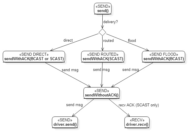
L3: Network Layer
- Adds network routing and mesh capabilities based on L2
- Based on new entities:
- Delivery Mode: Direct, Routed, Flood
- Network-level ACK (regardless of the routing mode)
- ACK with payload
- Routing Path
- Provides new functions:
- Ability to send a Direct (in-sight) message from source node to destination node
- Ability to send a Routed message using a known route (up to 8 intermediate hops)
- Ability to send a message using the Flood mechanism, which discovers a route to the destination node automatically
- Ability to send back a Routed ACK (optionally with payload) to the source node
- Automatic message rerouting on qualified nodes
- Automatic Flood message rebroadcasting on qualified nodes
Payload structure:
Nwk ID | Dst ID | Dst Port | L2 Payload
L2 Payload = Seq | Nwk Ctrl | Delivery Info | L3 Payload
Seq = Sequence Number
Nwk Ctrl = Direct OR Routed OR Flood | ACK Flag
Delivery Info = Direct Info OR Routed Info OR Flood Info
Direct Info = (empty/none)
Route Info = Node Count X | Routed Src ID | Node 1 | … | Node X | Routed Dst ID | Breadcrumb Bitfield
Flood Info = Discovered Node Count X | Flood Src ID | … | Flood Dst ID
Nwk Ctrl (network control) defines how a message should be delivered based on the following routing modes:
- Direct: classical "in sight" delivery from Src to Dst
- Routed: specifies all nodes (ordered) to be used as a delivery route between Routed Src and Routed Dst
- Flood: specifies only Flood Src and Flood Dst nodes, and sends the message as broadcast
- ACK: a bitflag defining a network-level ACK message for the above modes. ACK messages are created by the Dst node and sent back to Dst. When delivering Direct ACK the message is sent as a direct singlecast. For Routed ACK the entire route and order or nodes is preserved as in the original singlecast, but the intermediate hops resend the message to the next hop in the route in the reverse order (from Routed Dst to Routed Src). An ACK for the Flood delivery is always sent as a Routed ACK by using the route from the flood discovery
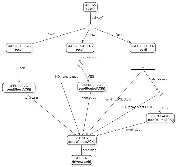
L3: Direct Mode
- If Src and Dst are within direct range the sender may decide to use Direct delivery
- In this mode Direct Info is currently defined as empty (no bytes) as no additional network control information is needed
- A message is sent from Src to Dst, and Dst replies with an ACK
- Direct mode can also be used for broadcast messages, which will be handled only within direct range (no routing). In this case Dst ID is set to 0xFF and no ACK is expected
In the below example we have Src ID 0x01 and Dst ID 0x05 exchanging one message and one ACK:
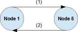
(1) Singlecast:
0xCO5A | 0x05 | 0x00 | Direct | L3 Payload

(2) Singlecast ACK:
0xCO5A | 0x01 | 0x00 | Direct + ACK | L3 ACK Payload
L3: Routed Mode
- Routing requires that the entire path/route of intermediate nodes is included in the Routing Info, as well as the source and destination nodes. Any intermediate hop, as well as the receiver, can also use container received route for maintenance purposes (e.g. update its routing table)
- Routed messages are always sent as singlecast
A routed message and ACK follows with one intermediate node with ID 0x02:
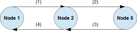
(1) Singlecast:
0xC05A | 0x02 | 0x00 | Routed | 1 | 0x01 | 0x02 | 0x05 | 0 | L3 Payload

(2) Singlecast:
0xC05A | 0x05 | 0x00 | Routed | 1 | 0x01 | 0x02 | 0x05 | 1 | L3 Payload

(3) Singlecast ACK:
0xC05A | 0x02 | 0x00 | Routed + ACK | 1 | 0x01 | 0x02 | 0x05 | 0 | L3 ACK Payload

(4) Singlecast ACK:
0xC05A | 0x01 | 0x00 | Routed + ACK | 1 | 0x01 | 0x02 | 0x05 | 1 | L3 ACK Payload
L3: Flood Mode
- Flood Mode allows the sender to not specify the exact routing path and let the listening and routing nodes help it resolve the route. The actual resolution is based on network "flooding", i.e. the routing nodes re-transmit the message further until it reaches the destination. The ultimate receiver then sends a Routed ACK using the route from the received flood message
- In order to avoid endless loops and duplicate re-transmissions every time a message is re-transmitted the intermediate node appends itself to the end of the routing list in the message (right before the Flood Dst ID). The maximum number of intermediate nodes (excluding Flood Src and Flood Dst) is 8 (eight)
- In the direction from the sender to the destination the broadcast method is used, since the route is unknown. The sender is not guaranteed to receive a network-level ACK and should instead listen for an ACK with a timeout before considering it failed
- There may be multiple ACKs generated from Flood Dst, each with a different route. These paths can be stored to improve the network robustness
- It is possible to send the L3 Payload with the original flood message (as in the example below), but that also means more RF load for the entire network. Instead, the current implementation first sends an empty (NOP) Flood message first and waits for an ACK from which to extract a valid route; then, it sends a Routed message with the discovered route, and waits for another ACK. This approach reduces the transmission times on all nodes across the network due to the smaller amount of data in the first step, and may be significant for larger networks. This approach also avoids the risk of delivering one and the same payload to the destination more than once (via different routes)
Example of flood delivery:
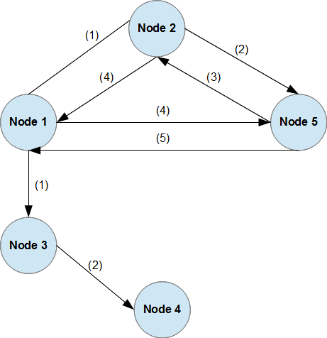
(1) Broadcast:
0xC05A | 0x00 | 0x00 | Flood | 0 | 0x01 | 0x05 | L3 Payload

(2) Broadcast:
0xC05A | 0x00 | 0x00 | Flood | 1 | 0x01 | 0x02 | 0x05 | L3 Payload

(3) Singlecast ACK:
0xC05A | 0x02 | 0x00 | Routed + ACK | 1 | 0x01 | 0x02 | 0x05 | 0 | L3 ACK Payload

(4) Singlecast ACK:
0xC05A | 0x01 | 0x00 | Routed + ACK | 1 | 0x01 | 0x02 | 0x05 | 1 | L3 ACK Payload

(5) Singlecast ACK:
0xC05A | 0x01 | 0x00 | Routed + ACK | 0 | 0x01 | 0x05 | 0 | L3 ACK Payload
The flexibility of Flood mode ACK handling also allows us to extend its usage to service discovery: Flood Dst Port can be used to designate some network-level service (similar to IP-based networks). For example, we can define a port to which Network Controllers would respond, but the sender doesn't need to have prior knowledge of its ID - it can be discovered via Flood mode automatically. In this case, Flood Dst ID could be defined as 0xFF (no concrete ID), while the port would typically be other than 0x00. For example:
0xC05A | 0xF0 | 0x00 | Flood | 0 | 0x01 | 0xFF | L3 Payload
As with the standard Flood delivery the intermediate nodes insert their IDs just before Flood Dst ID 0xFF and the flow process continues until it reaches a node, which can handle the request designated for Dst Port 0xFE. The handling node sends back a Routed ACK, but fills in the Routed Dst ID with its own node ID.
The original sender of the message needs to wait for an ACK for a potentially long time until it can consider the message failed. In theory, since MAX_ROUTING_HOPS is 8 the sender would need to wait for at least 8 times the maximum possible hops. The max time is currently calculated to be:
TIMEOUT_ACK_FLOOD = TIMEOUT_ACK_DIRECT * (MAX_ROUTING_HOPS + 2)
Where (in millis):
TIMEOUT_ACK_DIRECT = (uint16_t) TIMEOUT_ACK_RECEIVE * (DEFAULT_SEND_RETRY + 1)
TIMEOUT_ACK_RECEIVE = 500
DEFAULT_SEND_RETRY = 2
Which totals up to 15 seconds in the worst case with the current default values (which are also subject to fine-tuning). This is more than enough to ensure the message has (not) been delivered, and, besides reducing the timeouts and retries there is not much more that can be done algorithm-wise.
Still, there is a corner case that has recently been optimized. If the sender has no neighbor nodes in its direct range then it is fairly easy to "fail fast". Thus, a FLOOD ACK message has been introduced, which tells the sender that the FLOOD message has been received "at least once". If there is no recipient for this first hop then the sender fails much faster.
L3: Routed vs Flood Mode
- Differences:
- In case of Routed mode the route is known in advance, and carried in the Routed Info field, whereas in Flood only the Src and Dst nodes are filled out and the node list is expanded as we go (each traversed node adds itself to the list right before the Flood Dst node)
- In case of Routed mode we use Singlecast to send out and forward a message, whereas in Flood we use a Broadcast
- In case of Routed Mode we can expect an ACK, but this is not guaranteed with Flood
- Similarities:
- In both modes the ACK is delivered as Singlecast, not Broadcast
- Respective Info fields always contain at least the Src and Dst nodes
- The node list in both directions (send and ACK) is maintained in its original order (from Src to Dst)
L4: Network Management Layer
- Adds network management capabilities, such as:
- Network discovery
- Network services
- Adding and removing nodes to/from a network
- Node enumeration, discovery and rediscovery
- The current design does not require a well-known centralized "network controller", but rather uses the concept of services (combined with Flood delivery) to discover a node, which is able to provide the needed management functionality. Thus, network management can be carried out by multiple nodes in a distributed manner, while any possible synchronization between those management nodes (if needed) is carried out on higher levels of the stack
- Definition of Network Services is based on the Dst Port for any message sent. The L3 Payload of a message is specific to the target service itself, but advertising the service on the port level, which is already available on L2, allows us to have simple and efficient routing implementations, and to intercept service calls without the need for parsing these messages within the routing nodes
- Below are some service definitions and their respective ports:
| Port | Broadcast | Singlecast | Service | Description |
|---|---|---|---|---|
| 0xFF | Yes | Yes | NOP | No Operation service. Acts as a ping and expects an ACK on the same port from the destination node |
| 0xFE | Yes | Yes | Network Info Request | Requests network information (available nodes, etc.) |
| 0xFD | Yes | No | Add Mode Announce | Sent periodically by a node capable of adding new nodes |
| 0xFC | No | Yes | Add Mode Request | Sent by a device that would like to be included |
| 0xFB | Yes | No | Remove Mode Announce | Sent periodically by a node capable of removing nodes |
| 0xFA | No | Yes | Remove Mode Request | Sent by a device that would like to be removed |
| 0x64 - 0xF9 | - | - | - | Reserved for future usage |
| 0x00 - 0x63 | Yes | Yes | Application Service | 3rd-party application message ports (128 total) |
L4: NOP Service
- NOP service (No OPeration) can be used for "ping" services, much like it is used in IP networks
- NOP/Singlecast can be used with both Direct and Routed Modes
- NOP/Broadcast may technically be used with Direct Mode, but would only make sense for nodes in direct range
- NOP/Broadcast is typically meant to be used with Flood Mode, where we know the destination, but not the route
- The current implementation supports implicit NOP on L3 as well (when the L3 Payload is empty)
L4: Network Info Request
- Provides detailed information about the network
- At least, it needs to provide a list of known node IDs
- There may be multiple nodes that can respond to this request. How the information between them is synchronized is a matter of another service/mechanism
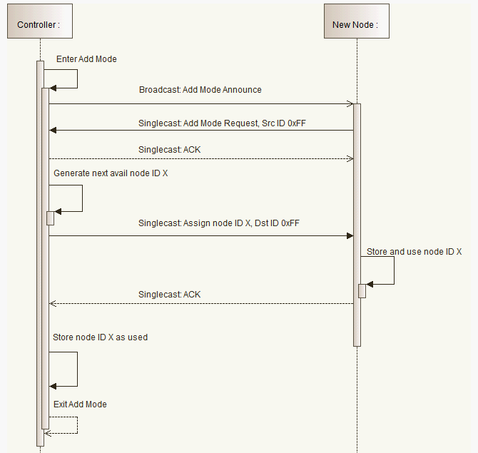
L4: Add Mode Announce
- A node capable of including a new device can send out periodic Add Mode Announces, whenever it is in "adding" mode. For simplicity, we can call these nodes "controllers". Announce messages are needed, so that devices, which are not yet part of the network can discover which network is currently open, and which node ID to talk to
- Add Mode Announce is delivered as Broadcast/Flood Mode with Dst Node 0x00, which means the entire network will be flooded and maximum range is guaranteed
- Once the new device has received the Add Mode Announce it will assume a temporary node ID 0xFF and send an Add Request message to the controller, which needs to ACK it. From this point on a route and communication between the controller and a new candidate for adding has been established and the real adding process can begin
L4: Add Mode Request
- New nodes joining the network must always assume a temporary node ID 0xFF and use it for communication with the respective controller, until the controller allocates and assigns a usable node ID for them
- The new node sends an Add Request to the controller (which then stops broadcasting Add Announce immediately). The controller responds with an ACK and then continues processing the request by allocating a new ID, sending it to the end device via Singlecast/Routed, which must ACK the message, so that the controller can consider the ID finally allocated (otherwise the allocation fails within a predefined timeout)
L4: Remove Mode Announce
- A node capable of removing a new device can send out periodic Remove Mode Announces, whenever it is in "removing" mode. For simplicity, we can call these nodes "controllers". Announce messages are needed, so that devices, which are part of the network can discover which node ID to talk to to ask for removal
- Remove Mode Announce is delivered as Broadcast/Floog Mode with Dst Node 0x00, which means the entire network will be flooded and maximum range is guaranteed
- Once a device has received the Remove Mode Announce it will send a Remove Request message to the controller
L4: Remove Mode Request
- A node sends a Remove Request to the controller (which then stops broadcasting Remove Mode Announce immediately). The controller responds with an ACK and then continues processing the request by sending a confirmation message to the end device, waiting for its ACK, and then removing the ID from the used list (otherwise the removal fails within a predefined timeout)
L4: Rules and Definitions
- Based on L2, L3 and L4 definitions we can now summarize some information
- Dst ID 0x00 is used for Broadcast messages
- Dst ID 0xFF is used as a temporary node ID for new nodes that are candidates for adding
- Dst Port 0x00-0x63 is available for 3rd-party code
- Dst Port 0x64-0xF9 is reserved by the protocol for future usage
- Dst Port 0xFA-0xFE is used for network management functions
- Dst Port 0xFF is used for NOP
Note that it is possible to use Meshwork without the L4 layer, if network management functionality is not required (or doesn't fit the MCU). In such case the network setup is done statically within the code and all mesh capabilities of the network are still preserved and utilized.
L4: Add Mode Sequence Example
L7 Message Port
The reserved message port for L7 Meshwork layer is 0x88 (136 dec).
L7 Payload Structure
| Byte | Parameter | Description |
|---|---|---|
| 0 | Command sequence number | |
| 1 | Command identifier | |
| 2-N | Command-specific data |
Command Seq notes:
- Values [0-127] signify a command sequence number
- Bit 7 set to high to denote that more response will follow. Bit 7 will further be referred to as MCFLAG (Multi-Command Flag)
- When bit 7 set to low means this was a last response to the specified command sequence
Command ID notes:
- Values [0-127] signify a valid command ID
- Bit 7 set to high to denote that the request is related to the command's meta information. Bit 7 will further be referred to as METAFLAG
- For the Meshwork-defined commands, the METAFLAG is only valid for PROPERTY_GET and PROPERTY_REP commands. Its usage elsewhere must result in ACK(Invalid)
- Command ID values [0-31] are reserved for Meshwork.
L7 Payload Commands
Only the following commands are defined by Meshwork. Custom commands can be added and handled by subclasses, as long as they reside outside of the Meshwork-reserved command range.
Generic Commands - Required
- ACK: mandatory immediate response to PROPERTY_GET, PROPERTY_SET, and META_XXX_GET
PROPERTY Commands - Required
- PROPERTY_GET
- PROPERTY_REP
- PROPERTY_SET
META Commands - Recommended
These are not mandatory, but highly recommended:
- META_DEVICE_GET
- META_DEVICE_REP
- META_CLUSTER_GET
- META_CLUSTER_REP
- META_ENDPOINT_GET
- META_ENDPOINT_REP
The reason why these are not required is to reduce the code size in wall-gardened environments, where cluster definitions and IDs are hard-coded at both the data producer and the consumer.
Command Specification
Generic Commands
ACK Command
| Byte | Parameter | Description |
|---|---|---|
| 0 | Command sequence number | |
| 1 | ACK | Message acknowledge |
| 2 | Message status | |
| 3-N | Status-specific data (optional) |
Status:
- Processed. MCFLAG must be low, since no further response is expected
- Data: N/A
- Invalid. MCFLAG must be low, since no further response is expected
- Data: N/A
- Forbidden. MCFLAG must be low, since no further response is expected
- Data: N/A
- Scheduled: scheduled for processing. MCFLAG must be high, as the sender should expect a response
- Data: approx. millis (16-bit) after which the message will be processed
- Not supported. MCFLAG must be low, since no further response is expected <<< TODO
- Data: N/A
PROPERTY Commands
PROPERTY_GET Command
| Byte | Parameter | Description |
|---|---|---|
| 0 | Command sequence number | |
| 1 | PROPERTY_GET | Get a property value |
| 2 | Cluster number | |
| 3 | Endpoint number |
PROPERTY_REP Command
| Byte | Parameter | Description |
|---|---|---|
| 0 | Command sequence number | |
| 1 | PROPERTY_REP | Report a property value |
| 2 | Cluster number | |
| 3 | Endpoint number | |
| 4-N | Endpoint type/subtype-specific data |
PROPERTY_SET Command
| Byte | Parameter | Description |
|---|---|---|
| 0 | Command sequence number | |
| 1 | PROPERTY_SET | Set a property value |
| 2 | Cluster number | |
| 3 | Endpoint number | |
| 4-N | Endpoint type/subtype-specific data |
META Commands
Note that Cluster=0xFF and Endpoint=0xFF are reserved.
META_DEVICE_GET Command
| Byte | Parameter | Description |
|---|---|---|
| 0 | Command sequence number | |
| 1 | META_DEVICE_GET | Device metadata information |
| 2 | Additional request flags |
Flags:
- 7b: Return information for all Endpoints (only if 0b set). Each META_CLUSTER_REP will be followed by META_ENDPOINT_REP for all contained endpoints
- 6b: Return information for all Clusters. META_DEVICE_REP will be followed by META_CLUSTER_REP for all contained clusters
- 0-5b: Reserved/ignored
META_DEVICE_REP Command
| Byte | Parameter | Description |
|---|---|---|
| 0 | Command sequence number | |
| 1 | META_DEVICE_REP | Report device metadata information |
| 2 | Device type | |
| 3 | Device subtype | |
| 4 | Number of clusters | |
| 5-N | Additional device data. Reserved |
MCFLAG must be set for all but the last message in the series if META_DEVICE_GET has Flags 7b and/or 6b set.
META_CLUSTER_GET Command
| Byte | Parameter | Description |
|---|---|---|
| 0 | Command sequence number | |
| 1 | META_CLUSTER_GET | Required metadata information |
| 2 | Additional request flags | |
| 3 | Cluster number |
Cluster:
- 0xFF: Return information for all Clusters. META_DEVICE_REP will be followed by META_CLUSTER_REP for all contained clusters. Flag 6b must be set
- 0x00-0xFE: A valid cluster number
Flags:
- 7b: Return information for all Endpoints (only if 0b set). Each META_CLUSTER_REP will be followed by META_ENDPOINT_REP for all contained endpoints
- 6b: Return information for all Clusters
- 0-6b: Reserved/ignored
META_CLUSTER_REP Command
| Byte | Parameter | Description |
|---|---|---|
| 0 | Command sequence number | |
| 1 | META_CLUSTER_REP | Report metadata information |
| 2 | Cluster number | |
| 3 | Cluster type | |
| 4 | Cluster subtype | |
| 5 | Total number of endpoints |
MCFLAG must be set for all but the last message in the series if META_CLUSTER_REP has Flags 7b and/or 6b set.
META_ENDPOINT_GET Command
| Byte | Parameter | Description |
|---|---|---|
| 0 | Command sequence number | |
| 1 | META_ENDPOINT_GET | Required metadata information |
| 2 | Additional request flags | |
| 3 | Cluster number | |
| 4 | Endpoint number |
Cluster:
- 0x00-0xFE: A valid cluster number
Flags:
- 7b: Return information for all Endpoints (only if 0b set)
- 0-6b: Reserved/ignored
META_ENDPOINT_REP Command
| Byte | Parameter | Description |
|---|---|---|
| 0 | Command sequence number | |
| 1 | META_ENDPOINT_REP | Report metadata information |
| 2 | Cluster number | |
| 3 | Endpoint number | |
| 4-5 | Endpoint type | |
| 6-7 | Unit type for the endpoint values |
MCFLAG must be set for all but the last message in the series if META_ENDPOINT_REP has Flags 7b and/or 6b set.
Endpoint Type values [0x0000-0x7FFF] are reserved for Meshwork.Unit Type values [0x0000-0x7FFF] are reserved for Meshwork.
Endpoint Types: Switches
Endpoint Types:
- ET_BINARYSWITCH
- ET_MULTILEVELSWITCH
PROPERTY_GET Data
No extra data.
PROPERTY_REP Data
| Byte | Parameter | Description |
|---|---|---|
| 4 | Current | Current value |
| 5 | Target | Target value |
The values are treated as unsigned bytes with the following range semantics:
- 0: 0%
- 255: 100%
Anything inbetween is interpolated freely by the device depending on the Endpoint type:
- ET_BINARYSWITCH: 1-254: 100%
- ET_MULTILEVELSWITCH: gradual or rounded step values between fully off/deactivated and fully on/activated
All reports must contain an actual target value, even if it has already been reached (i.e. Current=Target). Devices, which cannot physically support the requested target value (e.g. value 55 for ES_BINARYSWITCH) must store it and report back the requested target value (while recalculating the actual one internally).
After the (possibly recalculated) Target value has been reached the device must send PROPERTY_REP to:
- The device, which sent PROPERTY_GET. The Command Seq value must be maintained
- The device, which sent PROPERTY_SET that caused the change. The Command Seq value must be maintained
- The reporting node, according to the device's configuration (reporting node, discrete change, threshold change). The Command Seq value is arbitrary in this case
PROPERTY_SET Data
| Byte | Parameter | Description |
|---|---|---|
| 4 | Value | Switch value as unsigned byte |
| 5-6 | Time | Transition time in ms (unsigned short) |
Duration is specified in milliseconds as 2 bytes. Value 0 means to use the device's default transition time. The device is free to ignore the specified Time value completely if it does not support it.
Endpoint Types: Sensors
Endpoint Types:
- TYPE_SENSOR_BINARY
- TYPE_SENSOR_MULTILEVEL
- TYPE_SENSOR_VOLTAGE
- TYPE_SENSOR_TEMPERATURE
PROPERTY_GET Data
No extra data.
PROPERTY_REP Data
| Byte | Parameter | Description |
|---|---|---|
| 4-N | Value | Current value |
The structure of the Current value depends on the Endpoint type (see below).
The device must send PROPERTY_REP to:
- The device, which sent PROPERTY_GET. The Comand Seq value must be maintained
- The reporting node, according to the device's configuration (reporting node, discrete change, threshold change). The Comand Seq value is arbitrary in this case
TYPE_SENSOR_BINARY: Current
| Byte | Parameter | Description |
|---|---|---|
| 4 | Value | Current value (unsigned byte) |
The sematics of the values are:
- 0: deactivated
- 255: activated
The relative usage of these values (e.g. whether deactivated means that the door has been closed) is device model-specific.
TYPE_SENSOR_MULTILEVEL: Current
| Byte | Parameter | Description |
|---|---|---|
| 4-7 | Value | Current value |
Current value is in signed Q16.16 fixed point format.
TYPE_SENSOR_VOLTAGE: Current
| Byte | Parameter | Description |
|---|---|---|
| 4-7 | Value | Current value |
Current value is in signed Q16.16 fixed point format.
Supported units:
- UNIT_PERCENTAGE_BYTE
- UNIT_VOLT
TYPE_SENSOR_TEMPERATURE: Current
| Byte | Parameter | Description |
|---|---|---|
| 4-7 | Value | Current value |
Supported units:
- UNIT_TEMPERATURE_KELVIN
- UNIT_TEMPERATURE_CELSIUS
- UNIT_TEMPERATURE_FAHRENHEIT