---恢复内容开始---
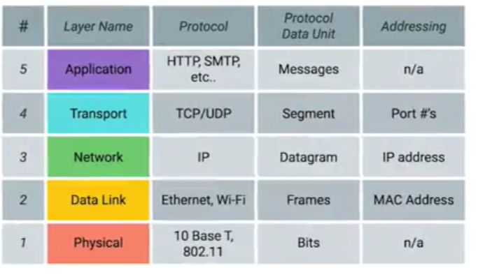
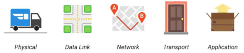
The TCP/IP Five-Layer Model
Network devices
1.cables:
copper cables: most commonly used, sending device communicates binary data across these copper wires by changing the voltage between two ranges.The system at the receiving end is able to interpret these voltage changes asbinary ones and zeros which can then be translated into different forms of data.
e.g. category five, category six cables,Cat5(older, mostly replaced by the following two), Cat5e(internals reduce crosstalk), and Cat6 cables (transfer data faster and more reliably than Cat5e cables can,have a shorter maximum distance when used at higher speeds.)
Fiber optic cables(fiber) are made out of glass, about the width of a human hair, used specifically in environments where there's a lot of electromagnetic interference from outside sources, quicker than copper wires but expansive and fragile, tranport data over a much longer distance than copper cables can without potential data loss, used much more in data centers than in offices or at home.
2. hub(集线器):
a physical layer or a level 1 device, allows for connections from many computers at once, rarely used today.
Hubs and switches are the primary devices used to connect computers on a single network, usually referred to as a LAN(local area network).
A collision domain: a network segment where only one device can communicate at a time.
If multiple systems try sending data at the same time, the electrical pulses sent across the cable can interfere with each other. This causes these systems to have to wait for a quiet period before they try sending their data again.
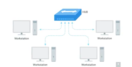
hub
3.switch(network switch, switching hub, "交换机")
a level 2 or data link device,a switch can actually inspect the contents of the Ethernet protocol data being sent around the network, determine which system the data is intended for and then only send that data to that one system, lead to fewer retransmissions and a higher overall throughput.
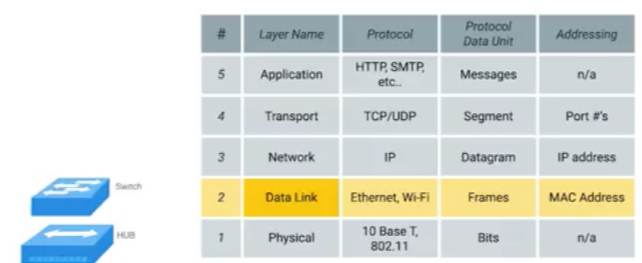
hub and switch at their own layer
4. router:
operates at network layer, forward data between independent networks.
routing table: route traffic between lots of different networks all over the world.
router in home network, or a small office: don't have very detailed routing tables, take traffic originating from inside the home, or office LAN, and to forward it along to the ISP(Internet Service Provider).
Routers share data with each other via BGP(Border Gateway Protocol, sort the most optimal paths to forward traffic.)
5. nodes
devices on the internet that communicate with each other are called nodes(计算机网络中信息收发的节点).
Physical layer: physical devices delivering bits(ones and zeros) between two individual nodes.
1.Modulation("调制“, called line coding "线路编码” in computer networks):
a way of varying the voltage of charge moving across the cable.
It allows devices on either end of a link to understand that an electrical charge in a certain state is a zero, and in another state is a one.
Modern networks are capable of moving10 billion ones and zeros across a single network cable every second.
2.Twisted pair cables:
most commonly used, copper, allow for duplex communication(information can flow in both directions across the cable simultaneously).
By reserving one or two pairs for communicating in one direction and then using the other one or two pairs for communicating in the other direction, devices on either side of a networking link can both communicate with each other simultaneously.
3. switches(have many network ports)- network ports(on a wall, below desk, on a PC, laptop, etc.connected to the network via cables)- LED lights(link light, activity light, indicate things like link and activity status, links speed)- patch panel(containing many net ports, a container for the endpoints of many runs of cable).
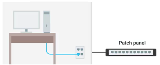
network ports and patch panel
Data link layer(network interface or network access layer): interpreting signals and getting data across a single link. One of the primary purposes of this layer is to essentially abstract away the need for any other layers to care about the physical layer and what hardware is in use.
Collision domain: a network segment where only one device can speak at a time, all data in a collision domain is sent to all the nodes connected to it, all devices on that segment receive all communication across the entire segment.
If two computers were to send data across the wire at the same time -> collisions of the electrical current representing ones and zeros, leaving the end result unintelligible.
Ethernet: the protocol most widely used to send data across individual links, cyclical redundancy check.
-> CSMA/CD(carrier sense multiple access with collision detection, "载波监听多路访问/冲突检测"): determine when the communications channels are clear and when the device is free to transmit data.
-> MAC address(media access control address, "媒体访问控制地址"), a globally unique identifier attached to an individual network interface, a 48-bit number normally represented by six groupings of two hexadecimal numbers or octet(any number that can be represented by 8 bits).
Ethernet uses MAC addresses to ensure it knows the source and destination of the data.
The first three octets of a MAC address is the organizationally unique identifier or OUI, assigned by IEEE, used to identify the manufacturer of a network interface.
The last three octets of MAC address, globally unique, assigned by the manufacturer.
Unicast: the least significant bit in the first octet of a destination address is set to zero, data would be sent to all devices on the collision domain, but only received and processed by the intended destination.
Multicast: the least significant bit in the first octet of a destination address is set to one, data would be sent to all devices on the collision domain and will be accepted or discarded by each device depending on criteria aside from their own hardware MAC address.
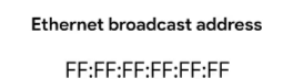
Broadcast: an Ethernet broadcast is sent to every single device on a LAN by using a broadcast address, which is all Fs.
Data packet: not tied to any specific layer, just a set of binary digits being sent across network link.
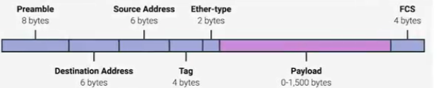
Ethernet frames("以太网帧"): data packets at the Ethernet level.
an ethernet frame
(1) Preamble
8 bytes or 64 bits long
the first seven bytes are a series of alternating ones and zeros, as a buffer between frames, synchronize internal clocks and to regulate the speed of sending data, used by the network interfaces.
the last byte is SFD(start frame delimiter,"开始帧定界符"),indicating that preamble is over.
(2) The destination MAC address.
(3) The source MAC address.
Each MAC address is 48 bits or 6 bytes long.
(4) The EtherType field("字段).
16 bits long, describe the protocol of the contents of the frame.
(5) A VLAN(virtual LAN)header
It indicates that the frame is a VLAN frame. If a VLAN header is present, the EtherType field follows it.
Virtual LAN: a technique making multiple logical LANs operating on the same physical equipment, usually used to segregate different forms of traffic.
Any frame with a VLAN tag will only be delivered out of a switch interface configured to relay that specific tag. This way you can have a single physical network that operates like it's multiple LANs.
(6) Payload("负载")
the actual data being transported, which is everything that isn't a header, can be anywhere from 46 to 1500 bytes long.
This contains all of the data from higher layers such as the IP, transport and application layers that's actually being transmitted.
(7) Frame check sequence("帧校验序列").
a 4-byte or 32-bit number, represents a checksum value for the entire frame, to ensure that the receiving network interface can infer if it received uncorrupted data, is calculated by performing a cyclical redundancy check against the frame.
Cyclical redundancy check or CRC: a mathematical transformation that uses polynomial division to create a number that represents a larger set of data.
When a device gets ready to send an Internet frame, it collects all the information we just covered, like the destination and originating MAC addresses, the data payload and so on. Then it performs a CRC against that data and attaches the resulting checksum number as the frame check sequence at the end of the frame. This data is then sent across a link and received at the other end. Here, all the various fields of the Ethernet frame are collected and now the receiving side performs a CRC against that data.
If the checksum computed by the receiving end doesn't match the checksum in the frame check sequence field, the data is thrown out. It's then up to a protocol at a higher layer to decide if that data should be retransmitted.
Ethernet itself only reports on data integrity. It doesn't perform data recovery.
cv
Network layer (the Internet layer): allows different networks to communicate with each other through routers, delivers data between two individual nodes.
IP address: 32-bit long numbers made up of 4 octets, and each octet is normally described in decimal numbers, hierarchical, distributed in large sections to various organizations and companies,instead of being determined by hardware vendors(like MAC address).
IBM owns every single IP that has the number 9 as the first octet.
8 bits of data, or a single octet, can represent all decimal numbers from 0 to 255.
IP addresses belong to the networks, not the devices attached to those networks. So your laptop will always have the same MAC address, no matter where you use it.
But it'll have a different IP address assigned to it depending on location.
Dynamic IP address- Dynamic Host Configuration Protocol- mostly for clients.
Static IP addresses- for servers and network devices
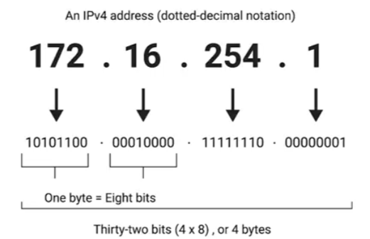
dotted decimal notation(点分十进制记法)
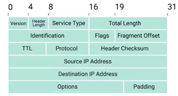
an IP datagram
IP datagram: a packet at the network layer under the IP protocol(data packet at the data link layer/Ethernet layer is Ethernet frame).
(1) Version field: what version of Internet protocol is being used.
The most common version of IP is version four or IPv4. Version six or IPv6, is rapidly seeing more widespread adoption.
(2) Header Length field: four bit, how long the entire header is.
Almost always 20 bytes in length when dealing with IPv4.
20 bytes is the minimum length of an IP header, couldn't fit all the data you need for a properly formatted IP header in any less space.
(3) Service Type field: QoS(quality of service) technologies: allow routers to make decisions about which IP datagram may be more important than others.
(4) Total Length field: the total length of the IP datagram.
16 bits altogether- the maximum size of a single datagram is the largest number can be represented with 16 bits: 65,535.
(5) Identification field: enables the receiving end to understand that every packet with the same value in that field is part of the same transmission.
If the total amount of data that needs to be sent is larger than what can fit in a single datagram(16 bits: 65,535), the IP layer needs to split this data up into many individual packets.
(6) The flag field: indicate if a datagram is allowed to be(or has already been) fragmented.
(7) Fragment offset: contains values used by the receiving end to take all the parts of a fragmented packet and put them back together in the correct order.
Fragmentation: splitting a single IP datagramup into several smaller datagrams if a datagram has to cross from a network allowing a larger datagram size to one with a smaller datagram size.
(8) TTL(Time to Live) field: how many router hops a datagram can traverse before it's thrown away.
Every time a datagram reaches a new router, that router decrements the TTL field by one. Once this value reaches zero, a router knows it doesn't have to forward the datagram any further, to avoid a misconfiguration in routing that causes an endless loop.
(9) Protocol field: what transport layer protocol is being used.
The most common transport layer protocols are TCP and UDP.
(10) Header checksum field: a checksum of the contents of the entire IP datagram header, functions very much like the Ethernet checksum.
Since the TTL field has to be recomputed at every router that a datagram touches, the checksum field necessarily changes, too.
(11) Source and destination IP address fields.
(12) IP options field: set special characteristics for datagrams primarily used for testing purposes.
(13) Padding field: the IP options field is both optional and variable in length, the padding field is a series of zeros used to ensure the header is the correct total size.
The entire contents of an IP datagram are encapsulated as the payload section of an Ethernet frame(encapsulation). IP datagram also has a payload section, the contents of which are the entirety of a TCP or UDP packet. -- Each layer is needed for the one above it.
IP addresses can be split into the network ID, and the host ID.
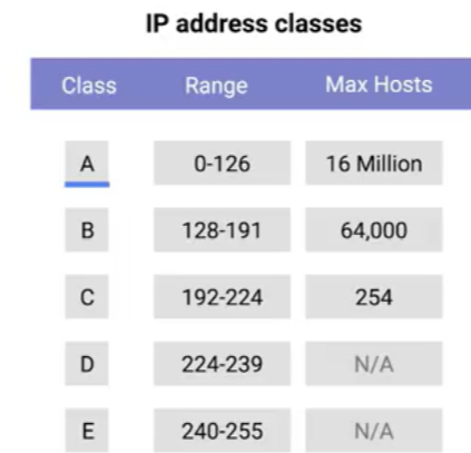
The address class system is a way of defining how the global IP address space is split up.
Class A addresses: the first octet is used for the network ID, and the last three are used for the host ID.
Class B addresses: the first two octets are used for the network ID, and the second two, are used for the host ID.
Class C addresses: the first three octets are used for the network ID, and only the final octet is used for the host ID.
A class A network has a total of 24 bits of host ID space- two to the twenty-fourth = 16,777,216 individual addresses.
A class C network, has eight bits of host ID space- two to the eighth = 256 addresses.
问问题做笔记
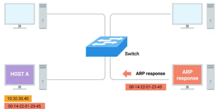
address resolution
ARP is a protocol used to discover the hardware address of a node with a certain IP address.
ARP table: a list of IP addresses and the MAC addresses associated with them.
Address resolution procedures:
- if no entry for some address in ARP table
- sends a broadcast ARP message to the Mac broadcast address which is all EFS(delivered to all computers on the local network)
- the network interface that's been assigned that IP receives this ARP broadcast and sends back an ARP response containing the MAC address
- the transmitting computer puts that MAC address in the destination hardware address field and the Ethernet frame is ready for delivery.
This IP address might be stored in its local ARP table for future use. But ARP table entries generally expire after a short amount of time to ensure changes in the network are accounted for.
Why subnetting:
- communicate with the IP address 9.100.100.100(belongs to the 9.0.0.0 class A network)
- core routers route the message to the gateway router looking at the network ID.
A gateway router is the entry and exit path to a certain network, while core Internet routers might only speak to other core routers.
- the packet gets to the gateway router for the 9.0.0.0 class A network, that router is now responsible for getting that data to the proper system by looking at the host ID.
A single class A network contains 16,777,216 individual IPs- too much - subnetting- split a large network up into many smaller ones.
These individual subnets will all have their own gateway routers serving as the ingress and egress point for each subnet.
Subnet mask
IP address is just a 32-bit number.
- In a world without subnets, a certain number of these bits are used for the network ID, and a certain number of the bits are used for the host ID.
- In a world with subnetting, some bits that would normally comprise the host ID are actually used for the subnet ID.
- At the internet level, core routers use the network ID to send the datagram to the appropriate gateway router to that network.
- That gateway router then has some additional information that it can use to send that datagram along to the destination machine or the next router in the path to get there.
- Finally, the host ID is used by that last router to deliver the datagram to the intended recipient machine.
Subnet IDs are calculated via a subnet mask, 32-bit numbers, normally written now as four octets in decimal.
A subnet mask is a binary number that has two sections
- the subnet mask, which is the part of the number with all the ones(subnet ID), what can be ignored when computing a host ID.
- The part with all the zeros tells us what is the host ID.
e.g., with the subnet mask of 255.255.255.0, only the last octet is available for host IDs, regardless of what size the network and subnet IDs are.
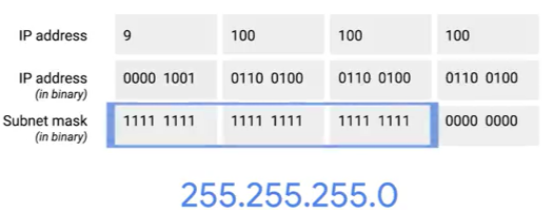
subnet mask for IP address 9.100.100.100
A single eight-bit number can represent 256 different numbers, the numbers 0-255.
A subnet can usually only contain two less than the total number of host IDs available(256), zero is generally not used and 255 is normally reserved as a broadcast address for the subnet.
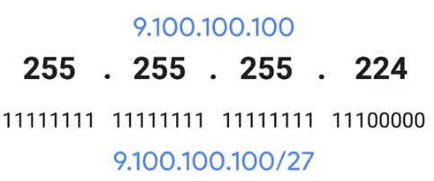
shorthand way of writing subnet mask for IP address 9.100.100.100
The subnet mask 255.255.255.224 would translate to 27 ones followed by five zeros. This means that we have five bits of host ID space or a total of 32 addresses.
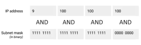
computing network ID or subnet ID
A subnet mask is a way for a computer to use and operators to determine if an IP address exists on the same network.
This means that the host ID portion is also known, since it will be anything left out.
For IP address 9.100.100.100 and our favorite subnet mask 255.255.255.0, once you put one on top of the other and perform a binary and operator on each column, you'll notice that the result is the network ID and subnet ID portion of IP address or 9.100.100.The computer that just performed this operation can now compare the results with its own network ID to determine if the address is on the same network or a different one.
Transport layer: sorts out the destination of data being sent.
Application layer.
---恢复内容结束---