作者信息:苗浩15515026488微信同号
本文摘抄自《华为ICT大赛-网络赛道学习空间(中国区)》,如有侵权,请及时联系作者删除文章
一、项目背景
某大型公司于2008年组建了全省公司专网,并依托该网络实现了全省多个分公司的统一组网。
现在由于基础网络带宽不足、设备老旧、网络规划混乱以及网络整体性能水平低下等问题,导致办公效率低下,对新技术、新终端支撑较差,影响公司业务发展。为了提高公司为了的整体性能、稳定性及可扩展性,该公司决定对总部和各分公司分阶段进行老旧设备替换以及整体网络改造升级。
第一阶段的网络方案需满足公司总部与分公司之间的互联互通。
为增加系统的可靠性和安全性,本次拟在核心交换、AC上进行冗余备份,有线与无线业务分设不同的网关,核心交换实现负载分担的同时,也提升了网络的可靠性;总部与分公司之间的通信使用MPLS VPN技术来实现,分公司的终端均能够访问总部网络的服务器资源,整合资源,减少管理和运维成本。
同时为了满足总部员工移动办公的需求,第一阶段,先在公司总部部署WLAN网络,覆盖整个总部网络,提升办公效率。
二、考试说明
2.1 试卷总分
考试分为路由交换、安全以及无线三个部分,总分为1000分。
2.2 设备介绍
2.2.1 设备清单
<1>两台USG6000防火墙(FW1-FW2)
<2>五台AR2220路由器(AR1-AR5)

<3>五台S5700交换机(SW1-SW5)
<4>两台AC6605控制器(AC1-AC2)
<5>一台AP7050(AP1)
<6>两台PC(PC1和PC2)
<7>一台笔记本(STA1)
<8>两台FTP终端(FTP终端1-FTP终端2)
<9>一台FTP Server
<10>一台DHCP Server
2.2.2 考试工具
<1>三台考试PC,PC上已有考试所需相关软件,以及所有涉及产品的产品文档。
三、考试正文
3.1 网络规划


3.2 设备命名
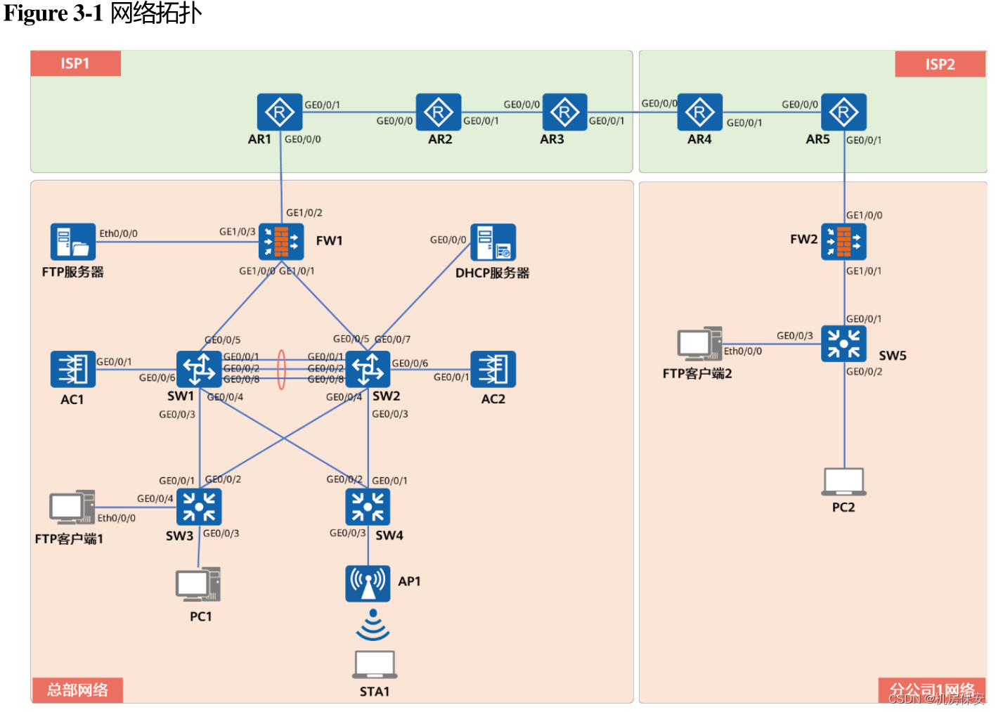
请根据Figure 3-1网络拓扑,配置或确认对应网络设备的名称。
配置过程:
#AR1
<Huawei>system-view
[Huawei]sysname AR1
[AR1]

#AR2
<Huawei>system-view
[Huawei]sysname AR2
[AR2]

#AR3
<Huawei>system-view
[Huawei]sysname AR3
[AR3]

#AR4
<Huawei>system-view
[Huawei]sysname AR4
[AR4]

#AR5
<Huawei>system-view
[Huawei]sysname AR5
[AR5]

#SW1
<Huawei>system-view
[Huawei]sysname SW1
[SW1]

#SW2
<Huawei>system-view
[Huawei]sysname SW2
[SW2]

#SW3
<Huawei>system-view
[Huawei]sysname SW3
[SW3]

#SW4
<Huawei>system-view
[Huawei]sysname SW4
[SW4]

#SW5
<Huawei>system-view
[Huawei]sysname SW5
[SW5]

#AC1
<AC6605>system-view
[AC6605]sysname AC1
[AC1]

#AC2
<AC6605>system-view
[AC6605]sysname AC2
[AC2]

#FW1
<USG6000V>system-view
[USG6000V]sysname FW1
[FW1]

#FW2
<USG6000V>system-view
[USG6000V]sysname FW2
[FW2]

#DHCP Server
<Huawei>system-view
[Huawei]sysname DHCP Server
[DHCP Server]
3.3 总部网络部署
3.3.1 设备链路部署
3.3.1.1 链路聚合部署
- 在核心交换SW1和SW2之间部署链路聚合技术,创建聚接口合编号为12,在实现带宽翻倍的同时,提高链路的冗余性。
- 链路聚合模式为LACP静态模式,SW1作为主动端设备。
配置过程:
#SW1
[SW1-Eth-Trunk12]mode lacp-static
[SW1]interface Eth-Trunk 12
[SW1-Eth-Trunk12]trunkport GigabitEthernet 0/0/1 0/0/2 0/0/8
[SW1]lacp priority 100

#SW2
[SW2-Eth-Trunk12]mode lacp-static
[SW2]interface Eth-Trunk 12
[SW2-Eth-Trunk12]trunkport GigabitEthernet 0/0/1 0/0/2 0/0/8
验证:


3.3.2 二层网络部署
3.3.2.1 VLAN规划与部署
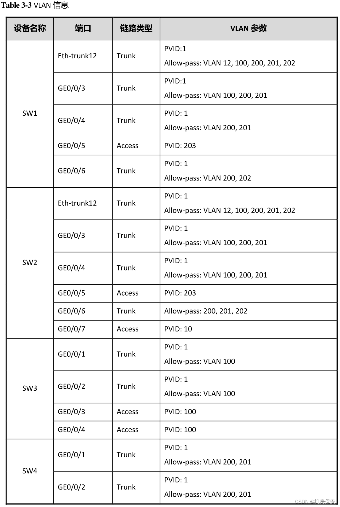
总部网络的VLAN规划如Table 3-3所示。
注:为了保证网络的连通性,以及避免二层环路隐患,交换机端口只允许规定的VLAN通过,多余的VLAN通过将影响整体网络稳定性评估。
配置过程:
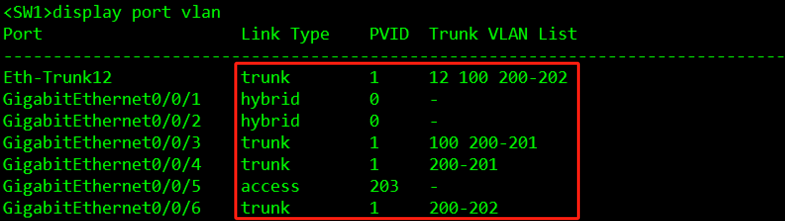
#SW1
[SW1]vlan batch 12 100 200 201 202 203
[SW1]interface Eth-Trunk 12
[SW1-Eth-Trunk12]port link-type trunk
[SW1-Eth-Trunk12]port trunk allow-pass vlan 12 100 200 201 202 203
[SW1-Eth-Trunk12]undo port trunk allow-pass vlan 1
[SW1]interface GigabitEthernet 0/0/3
[SW1-GigabitEthernet0/0/3]port link-type trunk
[SW1-GigabitEthernet0/0/3]port trunk allow-pass vlan 100 200 201
[SW1-GigabitEthernet0/0/3]undo port trunk allow-pass vlan 1
[SW1]interface GigabitEthernet 0/0/4
[SW1-GigabitEthernet0/0/4]port link-type trunk
[SW1-GigabitEthernet0/0/4]port trunk allow-pass vlan 200 201
[SW1-GigabitEthernet0/0/4]undo port trunk allow-pass vlan 1
[SW1]interface GigabitEthernet 0/0/5
[SW1-GigabitEthernet0/0/5]port link-type access
[SW1-GigabitEthernet0/0/5]port default vlan 203
[SW1]interface GigabitEthernet 0/0/6
[SW1-GigabitEthernet0/0/6]port link-type trunk
[SW1-GigabitEthernet0/0/6]port trunk allow-pass vlan 200 201 202
[SW1-GigabitEthernet0/0/6]undo port trunk allow-pass vlan 1
#SW2
[SW2]vlan batch 10 12 100 200 201 202 203
[SW2]interface Eth-Trunk 12
[SW2-Eth-Trunk12]port link-type trunk
[SW2-Eth-Trunk12]port trunk allow-pass vlan 12 100 200 201 202
[SW2-Eth-Trunk12]undo port trunk allow-pass vlan 1
[SW2]interface GigabitEthernet 0/0/3
[SW2-GigabitEthernet0/0/3]port link-type trunk
[SW2-GigabitEthernet0/0/3]port trunk allow-pass vlan 100 200 201
[SW2-GigabitEthernet0/0/3]undo port trunk allow-pass vlan 1
[SW2]interface GigabitEthernet 0/0/4
[SW2-GigabitEthernet0/0/4]port link-type trunk
[SW2-GigabitEthernet0/0/4]port trunk allow-pass vlan 100 200 201
[SW2-GigabitEthernet0/0/4]undo port trunk allow-pass vlan 1
[SW2]interface GigabitEthernet 0/0/5
[SW2-GigabitEthernet0/0/5]port link-type acces
[SW2-GigabitEthernet0/0/5]port default vlan 203
[SW2]interface GigabitEthernet 0/0/6
[SW2-GigabitEthernet0/0/6]port link-type trunk
[SW2-GigabitEthernet0/0/6]port trunk allow-pass vlan 200 201 202
[SW2-GigabitEthernet0/0/6]undo port trunk allow-pass vlan 1
[SW2]interface GigabitEthernet 0/0/7
[SW2-GigabitEthernet0/0/7]port link-type access
[SW2-GigabitEthernet0/0/7]port default vlan 10
#SW3
[SW3]vlan 100
[SW3]interface GigabitEthernet 0/0/1
[SW3-GigabitEthernet0/0/1]port link-type trunk
[SW3-GigabitEthernet0/0/1]port trunk allow-pass vlan 100
[SW3-GigabitEthernet0/0/1]undo port trunk allow-pass vlan 1
[SW3]interface GigabitEthernet 0/0/2
[SW3-GigabitEthernet0/0/2]port link-type trunk
[SW3-GigabitEthernet0/0/2]port trunk allow-pass vlan 100
[SW3-GigabitEthernet0/0/2]undo port trunk allow-pass vlan 1
[SW3]port-group group-member GigabitEthernet 0/0/3 GigabitEthernet 0/0/4
[SW3-port-group]port link-type access
[SW3-port-group]port default vlan 100
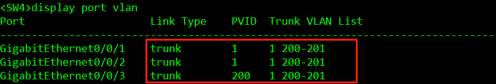
#SW4
[SW4]vlan batch 200 201
[SW4]port-group group-member GigabitEthernet 0/0/1 to GigabitEthernet 0/0/3
[SW4-port-group]port link-type trunk
[SW4-port-group]port trunk allow-pass vlan 200 201
[SW4]interface GigabitEthernet 0/0/3
[SW4-GigabitEthernet0/0/3]port trunk pvid vlan 200
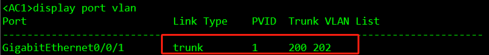
#AC1
[AC1]vlan batch 200 202
[AC1]interface GigabitEthernet 0/0/1
[AC1-GigabitEthernet0/0/1]port link-type trunk
[AC1-GigabitEthernet0/0/1]port trunk allow-pass vlan 200 202
[AC1-GigabitEthernet0/0/1]undo port trunk allow-pass vlan 1
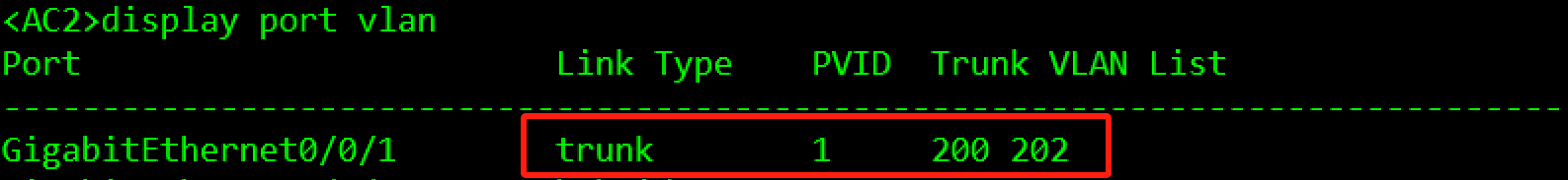
#AC2
[AC2]vlan batch 200 202
[AC2]interface GigabitEthernet 0/0/1
[AC2-GigabitEthernet0/0/1]port link-type trunk
[AC2-GigabitEthernet0/0/1]port trunk allow-pass vlan 200 202
[AC2-GigabitEthernet0/0/1]undo port trunk allow-pass vlan 1
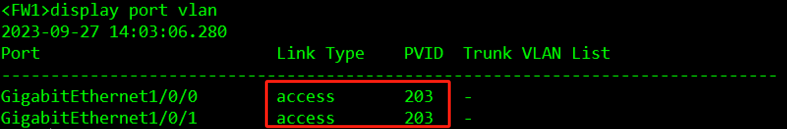
#FW1
[FW1]vlan 203
[FW1]interface GigabitEthernet 1/0/0
[FW1-GigabitEthernet1/0/0]portswitch
[FW1-GigabitEthernet1/0/0]port link-type access
[FW1-GigabitEthernet1/0/0]port default vlan 203
[FW1]interface GigabitEthernet 1/0/1
[FW1-GigabitEthernet1/0/1]portswitch
[FW1-GigabitEthernet1/0/1]port link-type access
[FW1-GigabitEthernet1/0/1]port default vlan 203
验证:


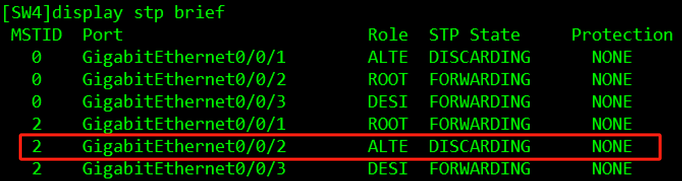
3.3.2.2 MSTP部署
- SW1、SW2、SW3、SW4都运行MSTP。
- VLAN100在Instance 1,在不使用命令修改桥优先级的情况下,需保证SW1作为实例1的根桥,SW2为备根桥。
- VLAN200和VLAN201在Instance 2,在不使用命令修改桥优先级的情况下,需保证SW2作为实例1的根桥,SW1为备根桥。
- MSTP的regoin name是huawei,Revision-level为12。
配置过程:
#SW1
[SW1]stp mode mstp
[SW1]stp region-configuration
[SW1-mst-region]region-name huawei
[SW1-mst-region]revision-level 12
[SW1-mst-region]instance 1 vlan 100
[SW1-mst-region]instance 2 vlan 200 201
[SW1-mst-region]active region-configuration
[SW1]stp instance 0 root primary
[SW1]stp instance 1 root primary
[SW1]stp instance 2 root secondary

#SW2
[SW2]stp mode mstp
[SW2]stp region-configuration
[SW2-mst-region]region-name huawei
[SW2-mst-region]revision-level 12
[SW2-mst-region]instance 1 vlan 100
[SW2-mst-region]instance 2 vlan 200 201
[SW2-mst-region]active region-configuration
[SW2]stp instance 0 root secondary
[SW2]stp instance 1 root secondary
[SW2]stp instance 2 root primary

#SW3
[SW3]stp mode mstp
[SW3]stp region-configuration
[SW3-mst-region]region-name huawei
[SW3-mst-region]revision-level 12
[SW3-mst-region]instance 1 vlan 100
[SW3-mst-region]instance 2 vlan 200 201
[SW3-mst-region]active region-configuration

#SW4
[SW4]stp mode mstp
[SW4]stp region-configuration
[SW4-mst-region]region-name huawei
[SW4-mst-region]revision-level 12
[SW4-mst-region]instance 1 vlan 100
[SW4-mst-region]instance 2 vlan 200 201
[SW4-mst-region]active region-configuration
验证:

3.3.3 三层网络部署
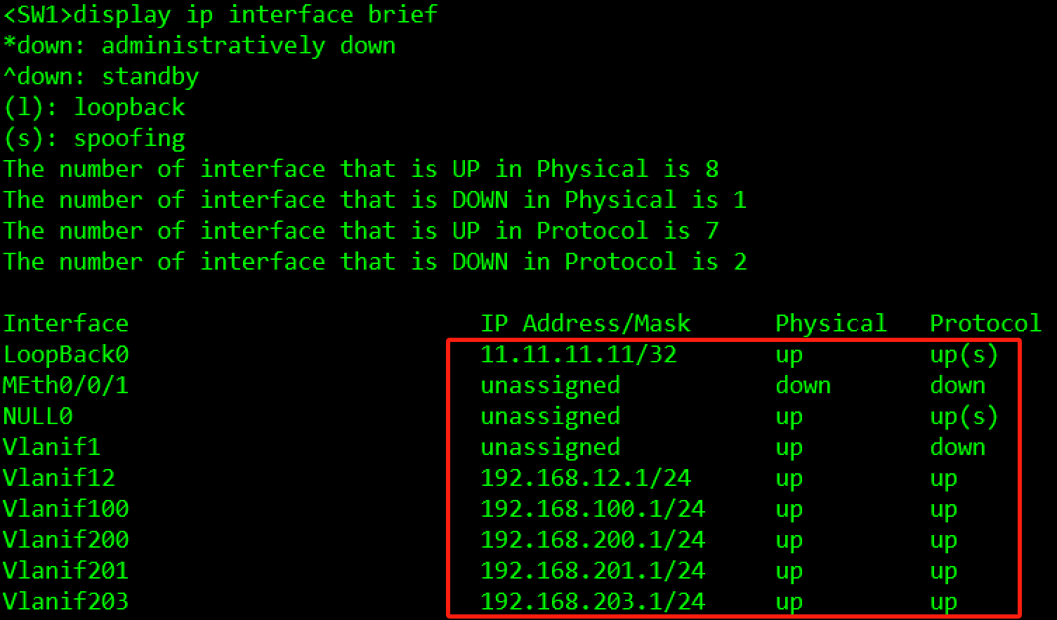
3.3.3.1 IP地址规划及配置
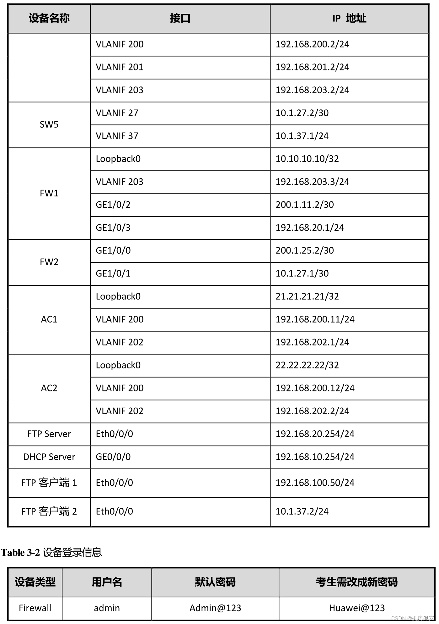
IP地址规划如Table 3-1 IP地址规划表所示,请按照规划正确配置IP地址。
配置过程:
#SW1
[SW1]interface LoopBack 0
[SW1-LoopBack0]ip address 11.11.11.11 32
[SW1]interface Vlanif 12
[SW1-Vlanif12]ip address 192.168.12.1 24
[SW1]interface Vlanif 100
[SW1-Vlanif100]ip address 192.168.100.1 24
[SW1]interface Vlanif 200
[SW1-Vlanif200]ip address 192.168.200.1 24
[SW1]interface Vlanif 201
[SW1-Vlanif201]ip address 192.168.201.1 24
[SW1]interface Vlanif 203
[SW1-Vlanif203]ip address 192.168.203.1 24
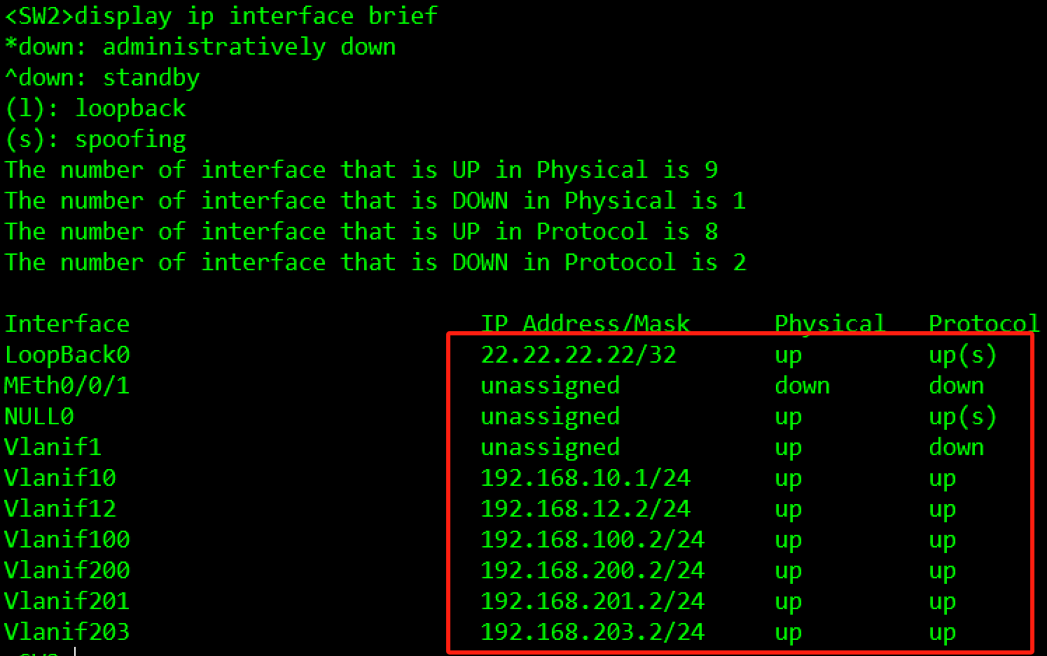
#SW2
[SW2]interface LoopBack 0
[SW2-LoopBack0]ip address 12.12.12.12 32
[SW2]interface Vlanif 10
[SW2-Vlanif12]ip address 192.168.10.1 24
[SW2]interface Vlanif 12
[SW2-Vlanif12]ip address 192.168.12.2 24
[SW2]interface Vlanif 100
[SW2-Vlanif100]ip address 192.168.100.2 24
[SW2]interface Vlanif 200
[SW2-Vlanif200]ip address 192.168.200.2 24
[SW2]interface Vlanif 201
[SW2-Vlanif201]ip address 192.168.201.2 24
[SW2]interface Vlanif 203
[SW2-Vlanif203]ip address 192.168.203.2 24
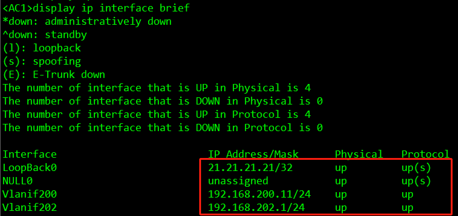
#AC1
[AC1]interface LoopBack 0
[AC1-LoopBack0]ip address 21.21.21.21 32
[AC1]interface Vlanif 200
[AC1-Vlanif200]ip address 192.168.200.11 24
[AC1]interface vlan 202
[AC1-Vlanif202]ip address 192.168.202.1 24
#AC2
[AC2]interface LoopBack 0
[AC2-LoopBack0]ip address 22.22.22.22 32
[AC2]interface Vlanif 200
[AC2-Vlanif200]ip address 192.168.200.12 24
[AC2]interface Vlanif 202
[AC2-Vlanif202]ip address 192.168.202.2 24
#DHCP Server
[DHCP Server]interface GigabitEthernet 0/0/0
[DHCP Server-GigabitEthernet0/0/0]ip address 192.168.10.254 24
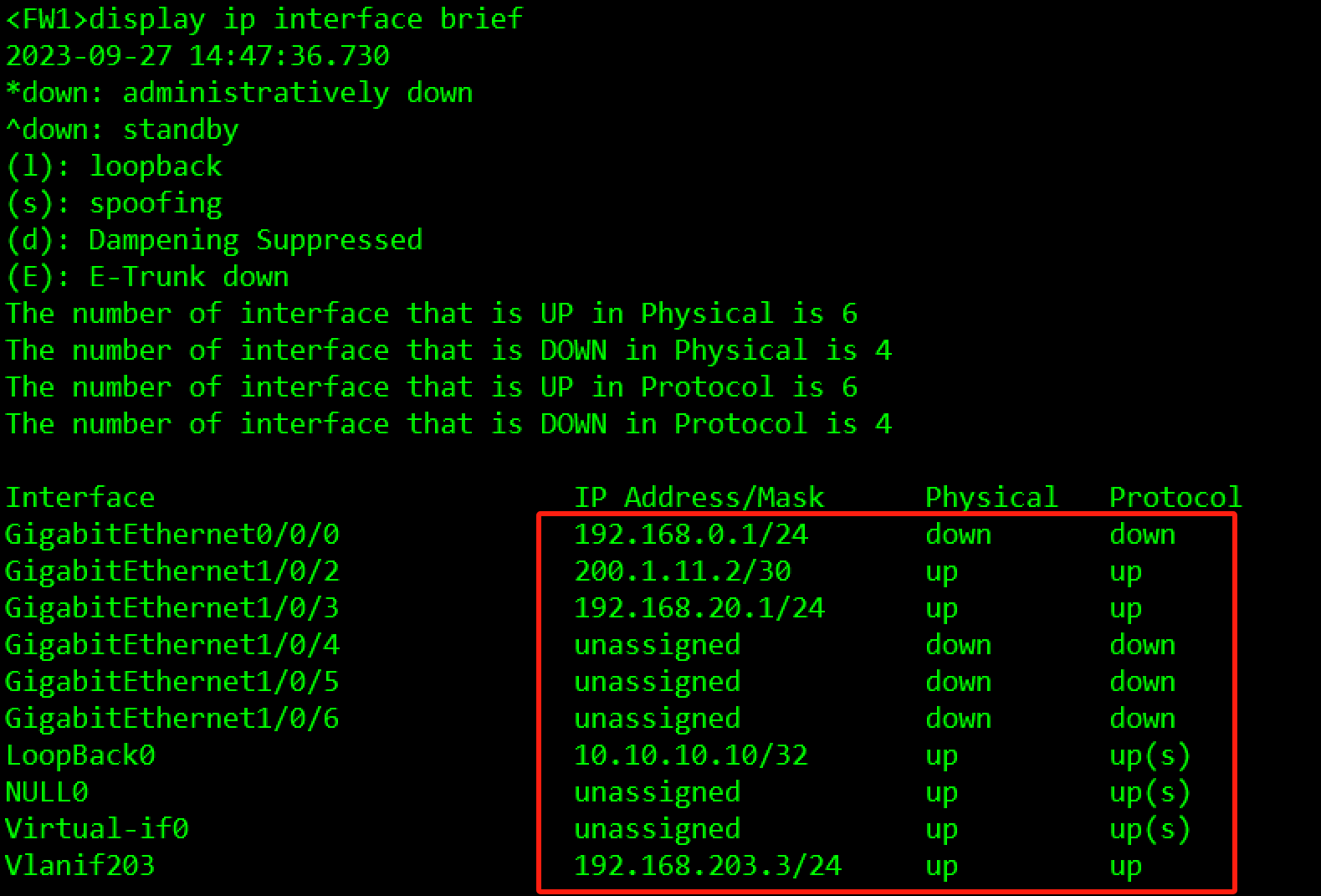
#FW1
[FW1]interface LoopBack 0
[FW1-LoopBack0]ip address 10.10.10.10 32
[FW1]interface Vlanif 203
[FW1-Vlanif203]ip address 192.168.203.3 24
[FW1]interface GigabitEthernet 1/0/2
[FW1-GigabitEthernet1/0/2]ip address 200.1.11.2 30
[FW1]interface GigabitEthernet 1/0/3
[FW1-GigabitEthernet1/0/3]ip address 192.168.20.1 24验证:


3.3.3.2 核心交换高可靠性规划与配置
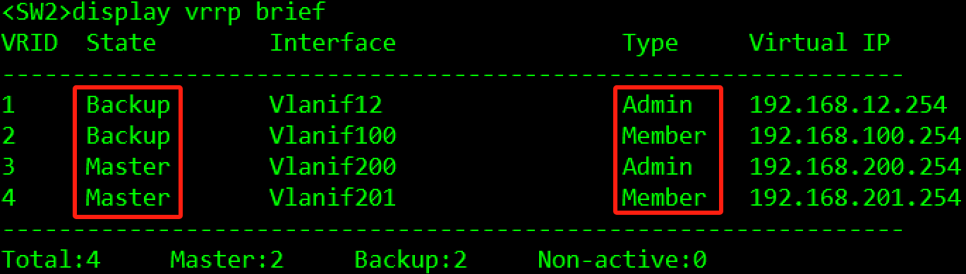
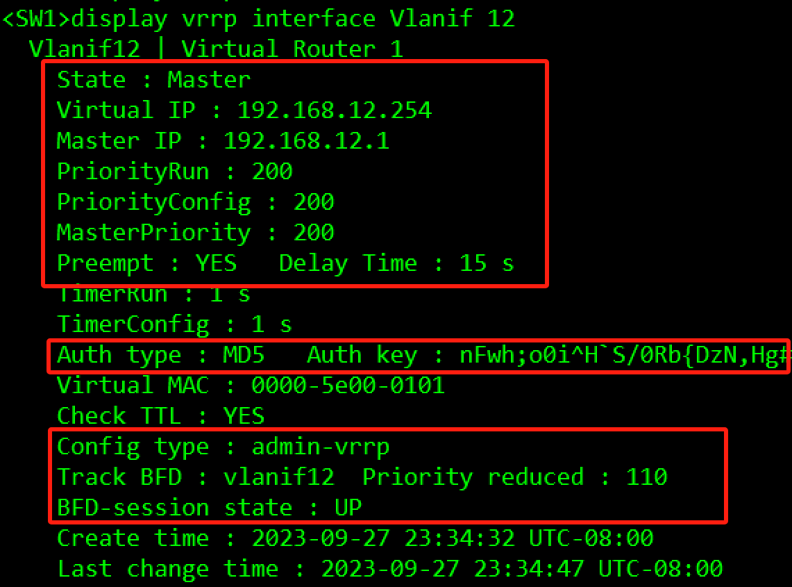
- 在SW1和SW2上创建VRRP备份组1,虚拟IP地址为192.168.12.254/24,配置SW1的优先级为200,抢占延时为15秒,作为Master设备;SW2的优先级为缺省值,作为Backup设备。
- 在VRRP备份组1中启动MD5认证,并将密码设置为Huawei。
- 在SW1和SW2上创建VRRP备份组2,虚拟IP地址为192.168.100.254/24,配置SW1的优先级为200,抢占延时为15秒,作为Master设备;SW2的优先级为缺省值,作为Backup设备。
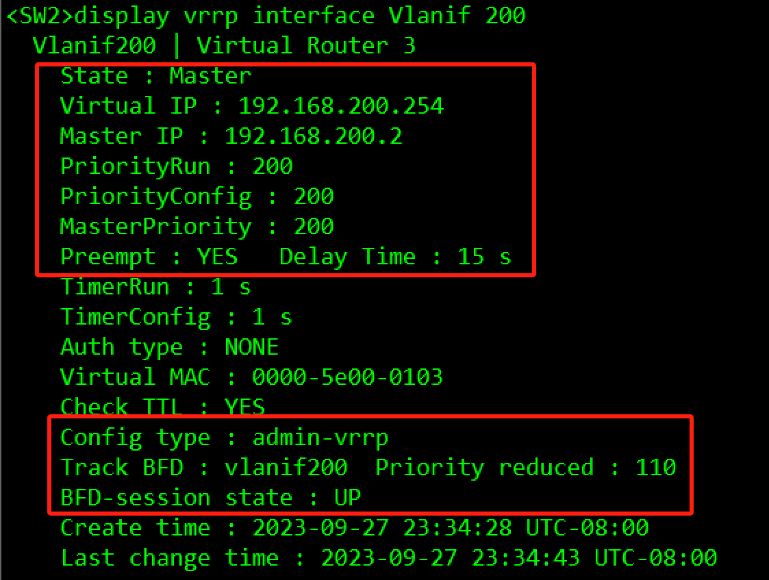
- 在SW1和SW2上创建VRRP备份组3,虚拟IP地址为192.168.200.254/24,配置SW2的优先级为200,抢占延时为15秒,作为Master设备;SW1的优先级为缺省值,作为Backup设备。
- 在SW1和SW2上创建VRRP备份组4,虚拟IP地址为192.168.201.254/24,配置SW2的优先级为200,抢占延时为15秒,作为Master设备;SW1的优先级为缺省值,作为Backup设备。
- 在VRRP备份组1和备份组2中,备份组1为管理组;在VRRP备份组3和备份组4中,备份组3为管理组。
- 为了加速主备切换,在SW1和SW2的备份组1和备份组3上,分别创建BFD会话,并绑定到对应的管理组中。
配置过程:
#SW1
[SW1]bfd
[SW1]bfd vlanif12 bind peer-ip 192.168.12.2 source-ip 192.168.12.1 auto
[SW1-bfd-session-vlanif12]commit
[SW1]bfd vlanif200 bind peer-ip 192.168.200.2 source-ip 192.168.200.1 auto
[SW1-bfd-session-vlanif200]commit
[SW1]interface Vlanif 12
[SW1-Vlanif12]vrrp vrid 1 virtual-ip 192.168.12.254
[SW1-Vlanif12]vrrp vrid 1 priority 200
[SW1-Vlanif12]vrrp vrid 1 preempt-mode timer delay 15
[SW1-Vlanif12]vrrp vrid 1 authentication-mode md5 Huawei
[SW1-Vlanif12]admin-vrrp vrid 1
[SW1-Vlanif12]vrrp vrid 1 track bfd-session session-name vlanif12 reduced 110
[SW1]interface Vlanif 100
[SW1-Vlanif100]vrrp vrid 2 virtual-ip 192.168.100.254
[SW1-Vlanif100]vrrp vrid 2 priority 200
[SW1-Vlanif100]vrrp vrid 2 preempt-mode timer delay 15
[SW1-Vlanif100]vrrp vrid 2 track admin-vrrp interface Vlanif 12 vrid 1 unflowdown
[SW1]interface Vlanif 200
[SW1-Vlanif200]vrrp vrid 3 virtual-ip 192.168.200.254
[SW1-Vlanif200]admin-vrrp vrid 3
[SW1]interface Vlanif 201
[SW1-Vlanif201]vrrp vrid 4 virtual-ip 192.168.201.254
[SW1-Vlanif201]vrrp vrid 4 track admin-vrrp interface Vlanif 200 vrid 3 unflowdown

#SW2
[SW2]bfd
[SW2]bfd vlanif12 bind peer-ip 192.168.12.1 source-ip 192.168.12.2 auto
[SW2-bfd-session-vlanif12]commit
[SW2]bfd vlanif200 bind peer-ip 192.168.200.1 source-ip 192.168.200.2 auto
[SW2-bfd-session-vlanif200]commit
[SW2]interface Vlanif 12
[SW2-Vlanif12]vrrp vrid 1 virtual-ip 192.168.12.254
[SW2-Vlanif12]vrrp vrid 1 authentication-mode md5 Huawei
[SW2-Vlanif12]admin-vrrp vrid 1
[SW2]interface Vlanif 100
[SW2-Vlanif100]vrrp vrid 2 virtual-ip 192.168.100.254
[SW2-Vlanif100]vrrp vrid 2 track admin-vrrp interface Vlanif 12 vrid 1 unflowdown
[SW2]interface Vlanif 200
[SW2-Vlanif200]vrrp vrid 3 virtual-ip 192.168.200.254
[SW2-Vlanif200]vrrp vrid 3 priority 200
[SW2-Vlanif200]vrrp vrid 3 preempt-mode timer delay 15
[SW2-Vlanif200]admin-vrrp vrid 3
[SW2-Vlanif200]vrrp vrid 3 track bfd-session session-name vlanif200 reduced 110
[SW2]interface Vlanif 201
[SW2-Vlanif201]vrrp vrid 4 virtual-ip 192.168.201.254
[SW2-Vlanif201]vrrp vrid 4 priority 200
[SW2-Vlanif201]vrrp vrid 4 preempt-mode timer delay 15
[SW2-Vlanif201]vrrp vrid 4 track admin-vrrp interface Vlanif 200 vrid 3 unflowdown
验证:

3.3.3.3 IGP协议部署
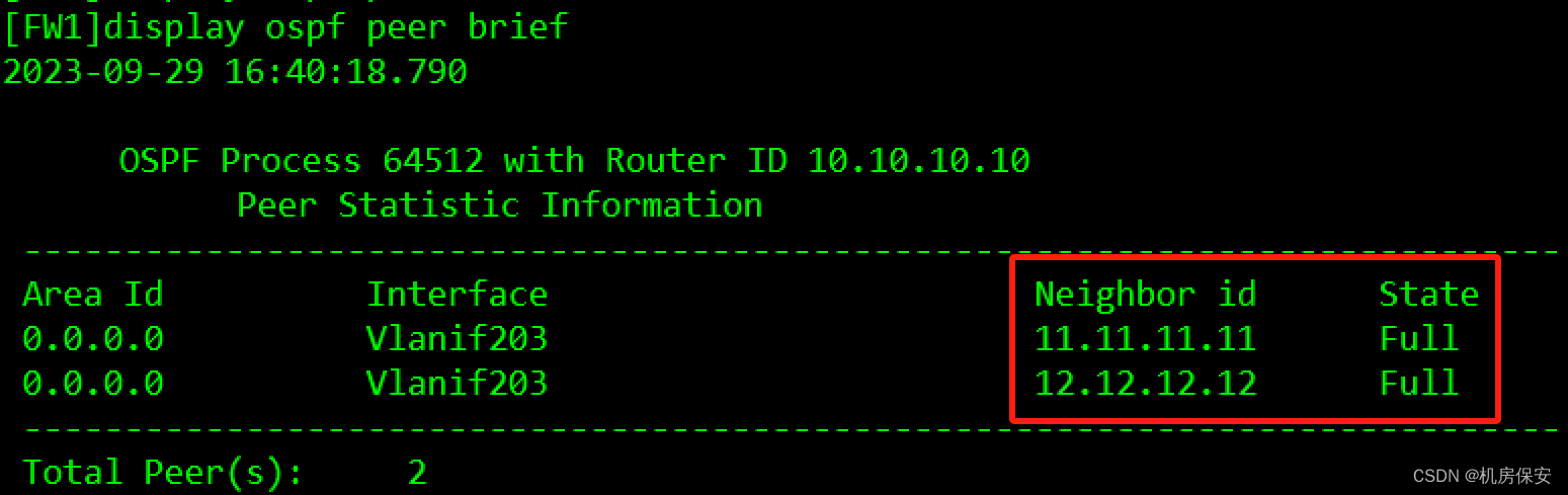
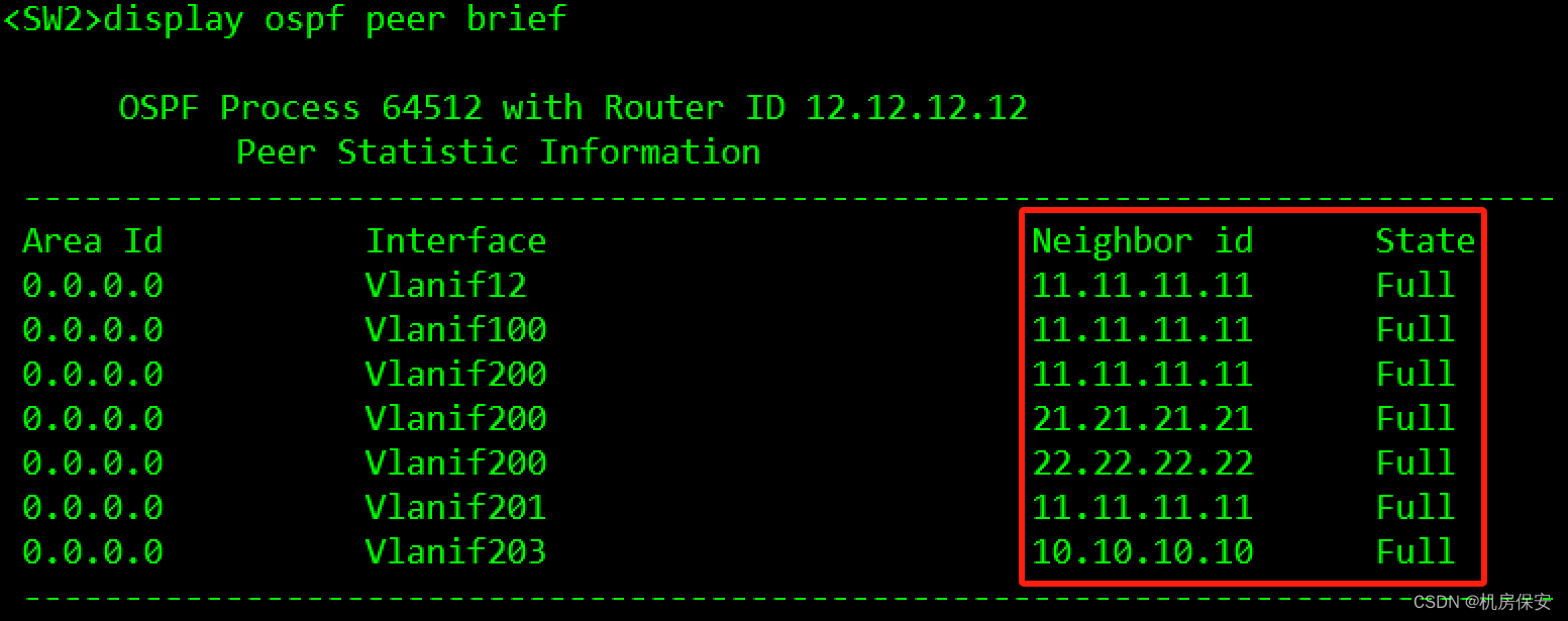
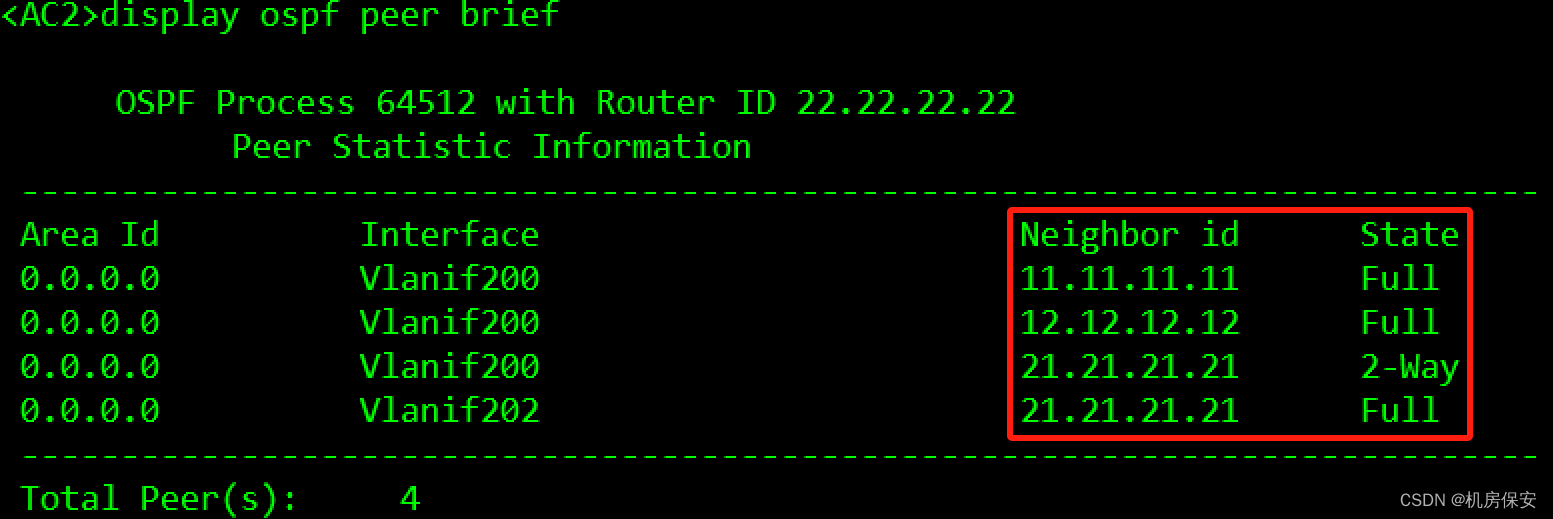
- 为了保证总部无线网络与有线网络之间能够互通,在SW1、SW2、AC1、AC2以及FW1之间部署了OSPF协议。
- OSPF的进程号为64512,全部设备的接口均处于骨干区域内,使用Loopback 0口作为router-id,各网段需要精确宣告。
- 使用import命令,将DHCP服务器的直连网段引入到OSPF当中(不能引入其他网段路由)。
配置过程:
#SW1
[SW1]ospf 64512 router-id 11.11.11.11
[SW1-ospf-64512]area 0
[SW1-ospf-64512-area-0.0.0.0]network 11.11.11.11 0.0.0.0
[SW1-ospf-64512-area-0.0.0.0]network 192.168.12.1 0.0.0.0
[SW1-ospf-64512-area-0.0.0.0]network 192.168.100.1 0.0.0.0
[SW1-ospf-64512-area-0.0.0.0]network 192.168.200.1 0.0.0.0
[SW1-ospf-64512-area-0.0.0.0]network 192.168.201.1 0.0.0.0
[SW1-ospf-64512-area-0.0.0.0]network 192.168.203.1 0.0.0.0
[SW1]ip route-static 0.0.0.0 0.0.0.0 192.168.203.3

#SW2
[SW2]ip ip-prefix dhcp_direct permit 192.168.10.0 24
[SW2]route-policy dhcp_direct permit node 10
[SW2-route-policy]if-match ip-prefix dhcp_direct
[SW2]ospf 64512 router-id 22.22.22.22
[SW2-ospf-64512]import-route direct route-policy dhcp_direct type 1
[SW2-ospf-64512]area 0
[SW2-ospf-64512-area-0.0.0.0]network 22.22.22.22 0.0.0.0
[SW2-ospf-64512-area-0.0.0.0]network 192.168.12.2 0.0.0.0
[SW2-ospf-64512-area-0.0.0.0]network 192.168.100.2 0.0.0.0
[SW2-ospf-64512-area-0.0.0.0]network 192.168.200.2 0.0.0.0
[SW2-ospf-64512-area-0.0.0.0]network 192.168.201.2 0.0.0.0
[SW2-ospf-64512-area-0.0.0.0]network 192.168.203.2 0.0.0.0
[SW2]ip route-static 0.0.0.0 0.0.0.0 192.168.203.3

#AC1
[AC1]ospf 64512 router-id 21.21.21.21
[AC1-ospf-64512]area 0
[AC1-ospf-64512-area-0.0.0.0]network 21.21.21.21 0.0.0.0
[AC1-ospf-64512-area-0.0.0.0]network 192.168.200.11 0.0.0.0
[AC1-ospf-64512-area-0.0.0.0]network 192.168.202.1 0.0.0.0
[AC1]interface Vlanif 200
[AC1-Vlanif200]ospf dr-priority 0

#AC2
[AC2]ospf 64512 router-id 22.22.22.22
[AC2-ospf-64512]area 0
[AC2-ospf-64512-area-0.0.0.0]network 22.22.22.22 0.0.0.0
[AC2-ospf-64512-area-0.0.0.0]network 192.168.200.12 0.0.0.0
[AC2-ospf-64512-area-0.0.0.0]network 192.168.202.2 0.0.0.0
[AC2]interface Vlanif 200
[AC2-Vlanif200]ospf dr-priority 0

#FW1
[FW1]ip route-static 0.0.0.0 0.0.0.0 200.1.11.1
[FW1]ospf 64512 router-id 10.10.10.10
[FW1-ospf-64512]default-route-advertise type 1
[FW1-ospf-64512]area 0
[FW1-ospf-64512-area-0.0.0.0]network 10.10.10.10 0.0.0.0
[FW1-ospf-64512-area-0.0.0.0]network 192.168.20.1 0.0.0.0
[FW1-ospf-64512-area-0.0.0.0]network 192.168.203.3 0.0.0.0
验证:没有配置防火墙安全区域的时候,OSPF邻居会卡在Exstart状态。


3.3.4 服务器部署
3.3.4.1 DHCP服务器部署
- 在DHCP Server上创建基于全局的DHCP地址池为有线,无线终端及AP提供地址池分配服务,网关部署在SW1和SW2上,由于核心交换与DHCP服务器不在同一个网段,需要想办法让AP、PC和STA能够获取到IP地址,具体地址池信息如下表
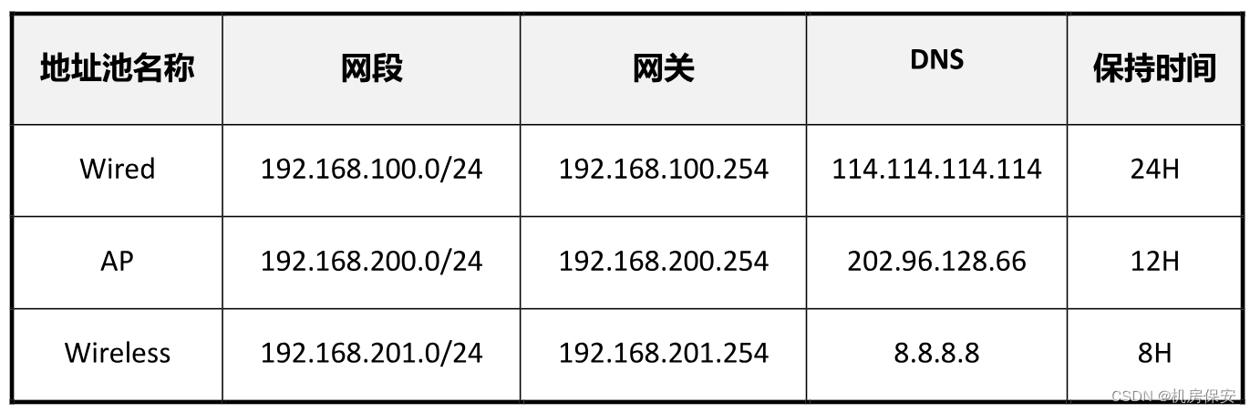
- 地址池需排除已经被使用过的IP地址。
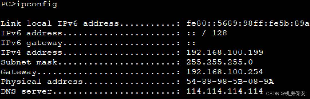
- 要求PC1能够获取到固定的IP地址,为192.168.100.199。
配置过程:
#DHCP Server
[DHCP Server]ip route-static 0.0.0.0 0.0.0.0 192.168.10.1
[DHCP Server]dhcp enable
[DHCP Server]ip pool Wired
[DHCP Server-ip-pool-Wired]network 192.168.100.0 mask 255.255.255.0
[DHCP Server-ip-pool-Wired]gateway-list 192.168.100.254
[DHCP Server-ip-pool-Wried]dns-list 114.114.114.114
[DHCP Server-ip-pool-Wired]static-bind ip-address 192.168.100.199 mac-address 5489-985A-089A
[DHCP Server]ip pool AP
[DHCP Server-ip-pool-AP]network 192.168.200.0 mask 24
[DHCP Server-ip-pool-AP]gateway-list 192.168.200.254
[DHCP Server-ip-pool-AP]dns-list 202.96.128.66
[DHCP Server-ip-pool-AP]lease day 0 hour 12
[DHCP Server-ip-pool-AP]option 43 ip-address 21.21.21.21 22.22.22.22
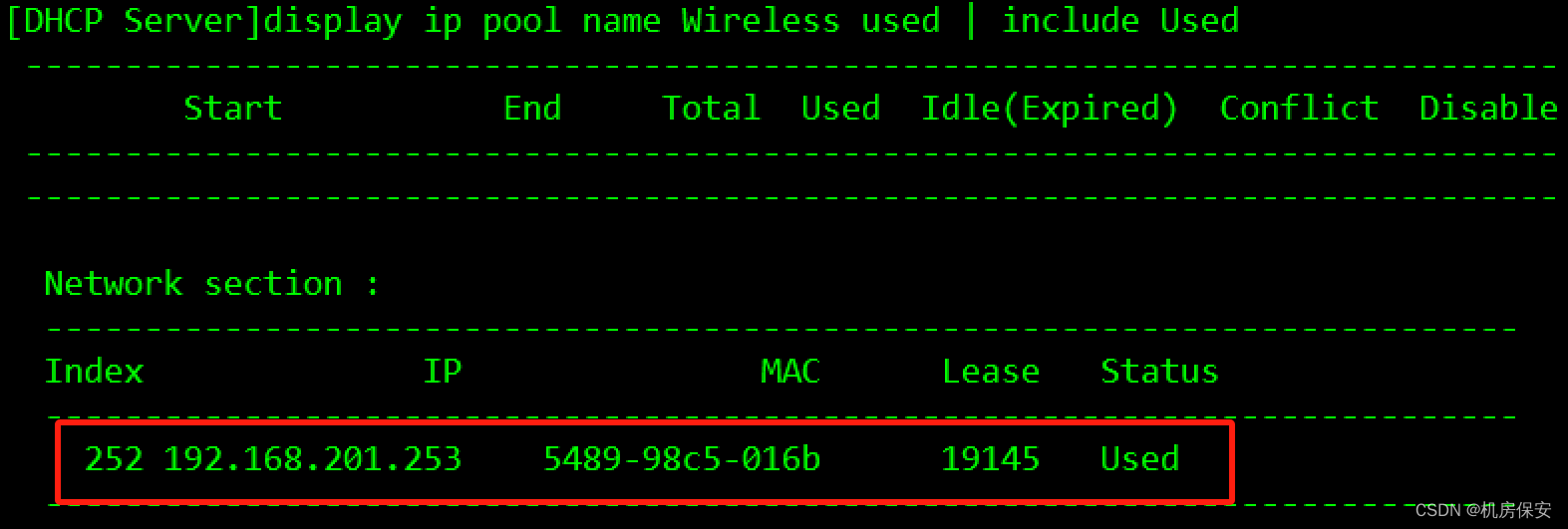
[DHCP Server]ip pool Wireless
[DHCP Server-ip-pool-Wireless]network 192.168.201.0 mask 24
[DHCP Server-ip-pool-Wireless]gateway-list 192.168.201.254
[DHCP Server-ip-pool-Wireless]dns-list 8.8.8.8
[DHCP Server-ip-pool-Wireless]lease day 0 hour 8
[DHCP Server]interface GigabitEthernet 0/0/0
[DHCP Server-GigabitEthernet0/0/0]dhcp select global
#SW1
[SW1]dhcp enable
[SW1]interface Vlanif 100
[SW1-Vlanif100]dhcp select relay
[SW1-Vlanif100]dhcp relay server-ip 192.168.10.254
[SW1]interface Vlanif 200
[SW1-Vlanif200]dhcp select relay
[SW1-Vlanif200]dhcp relay server-ip 192.168.10.254
[SW1]interface Vlanif 201
[SW1-Vlanif201]dhcp select relay
[SW1-Vlanif201]dhcp relay server-ip 192.168.10.254
#SW2
[SW2]dhcp enable
[SW2]interface Vlanif 100
[SW2-Vlanif100]dhcp select relay
[SW2-Vlanif100]dhcp relay server-ip 192.168.10.254
[SW2]interface Vlanif 200
[SW2-Vlanif200]dhcp select relay
[SW2-Vlanif200]dhcp relay server-ip 192.168.10.254
[SW2]interface Vlanif 201
[SW2-Vlanif201]dhcp select relay
[SW2-Vlanif201]dhcp relay server-ip 192.168.10.254
排除地址命令:
[DHCP Server-ip-pool-AP]excluded-ip-address xx.xx.xx.xx验证:

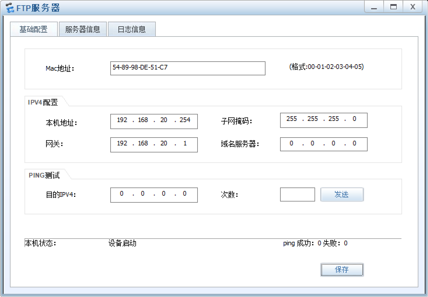
3.3.4.2 FTP服务器部署
随便找个目录点启动就行

3.3.5 WLAN网络部署
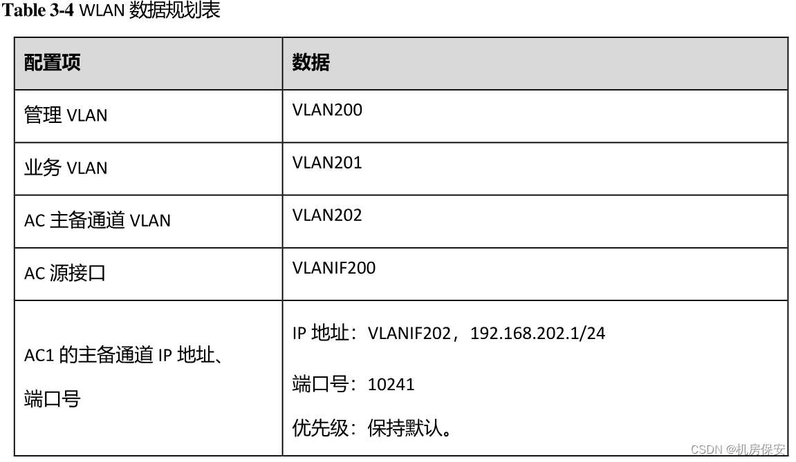
3.3.5.1 WLAN基础参数规划

配置过程:
#AC1
[AC1]capwap source interface LoopBack 0
[AC1]wlan
[AC1-wlan-view]ap-group name huawei
[AC1-wlan-ap-group-huawei]quit
[AC1-wlan-view]ap auth-mode mac-auth
[AC1-wlan-view]ap-id 1 ap-mac 00e0-fc52-7250
[AC1-wlan-ap-1]ap-name AP1
[AC1-wlan-ap-1]ap-group huawei
[AC1-wlan-view]regulatory-domain-profile name huawei
[AC1-wlan-regulate-domain-huawei]country-code CN
[AC1-wlan-view]ssid-profile name huawei
[AC1-wlan-ssid-prof-huawei]ssid Huawei-ICT2020
[AC1-wlan-view]security-profile name huawei
[AC1-wlan-sec-prof-huawei]security wpa-wpa2 psk pass-phrase Huawei-ICT2020 aes-tkip
[AC1-wlan-view]vap-profile name huawei
[AC1-wlan-vap-prof-huawei]service-vlan vlan 201
[AC1-wlan-vap-prof-huawei]ssid-profile huawei
[AC1-wlan-vap-prof-huawei]security-profile huawei
[AC1-wlan-view]ap-group name huawei
[AC1-wlan-ap-group-huawei]regulatory-domain-profile huawei
[AC1-wlan-ap-group-huawei]vap-profile huawei wlan 1 radio all

#AC2
[AC2]capwap source interface LoopBack 0
[AC2]wlan
[AC2-wlan-view]ap-group name huawei
[AC2-wlan-ap-group-huawei]quit
[AC2-wlan-view]ap auth-mode mac-auth
[AC2-wlan-view]ap-id 1 ap-mac 00e0-fc52-7250
[AC2-wlan-ap-1]ap-name AP1
[AC2-wlan-ap-1]ap-group huawei
[AC2-wlan-view]regulatory-domain-profile name huawei
[AC2-wlan-regulate-domain-huawei]country-code CN
[AC2-wlan-view]ssid-profile name huawei
[AC2-wlan-ssid-prof-huawei]ssid Huawei-ICT2020
[AC2-wlan-view]security-profile name huawei
[AC2-wlan-sec-prof-huawei]security wpa-wpa2 psk pass-phrase Huawei-ICT2020 aes-tkip
[AC2-wlan-view]vap-profile name huawei
[AC2-wlan-vap-prof-huawei]service-vlan vlan 201
[AC2-wlan-vap-prof-huawei]ssid-profile huawei
[AC2-wlan-vap-prof-huawei]security-profile huawei
[AC2-wlan-view]ap-group name huawei
[AC2-wlan-ap-group-huawei]regulatory-domain-profile huawei
[AC2-wlan-ap-group-huawei]vap-profile huawei wlan 1 radio all
验证:
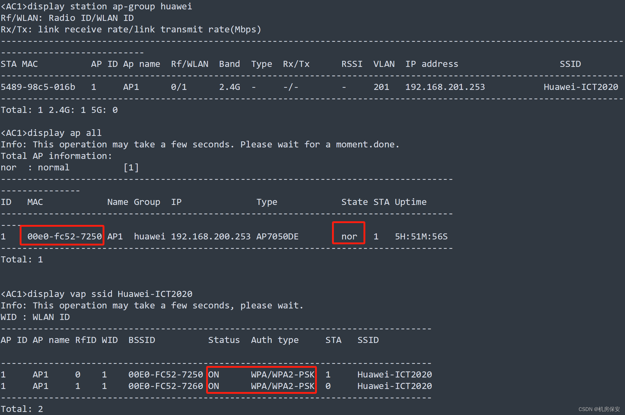
3.3.5.2 无线射频规划(这个做的不完善,有懂得同学可以交流一下)
- 对AP组下的射频资源进行统一规划。
- 将2.4GHz的信道带宽设置成40MHz,且使用1和5信道进行信道绑定。
- 将第一个5GMHz射频口的信道带宽设置成80MHz,且使用36~48信道进行信道绑定。
- 将第二个5GMHz射频口的信道带宽设置成80MHz,且使用149~161信道进行信道绑定。
配置过程:
#AC2
[AC2]wlan
[AC2-wlan-view]rrm-profile name huawei
[AC2-wlan-rrm-prof-huawei]calibrate auto-channel-select disable
[AC2-wlan-rrm-prof-huawei]calibrate auto-txpower-select disable
[AC2-wlan-view]air-scan-profile name huawei
[AC2-wlan-air-scan-prof-huawei]scan-channel-set country-channel
[AC2-wlan-air-scan-prof-huawei]scan-period 80
[AC2-wlan-air-scan-prof-huawei]scan-interval 80000
[AC2-wlan-view]radio-2g-profile name huawei
[AC2-wlan-radio-2g-prof-huawei]rrm-profile huawei
[AC2-wlan-radio-2g-prof-huawei]air-scan-profile huawei
[AC2-wlan-view]radio-5g-profile name huawei
[AC2-wlan-radio-5g-prof-huawei]rrm-profile huawei
[AC2-wlan-radio-5g-prof-huawei]air-scan-profile huawei
[AC2-wlan-ap-group-huawei]radio-2g-profile huawei radio 0
[AC2-wlan-ap-group-huawei]radio-5g-profile huawei radio 1
[AC2-wlan-ap-group-huawei]radio-5g-profile huawei radio 2
3.3.5.3 AC双机热备
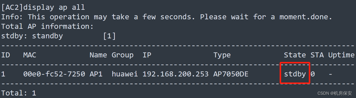
- 部署双链路备份,使AC1作为主用AC,AC2作为备用AC。
- 部署双机热备份,主备AC能够同步AP信息以及STA信息。
配置过程:这里做主备时候按照题目要求的地址做,我是做完了懒得改了
#AC1
[AC1]wlan
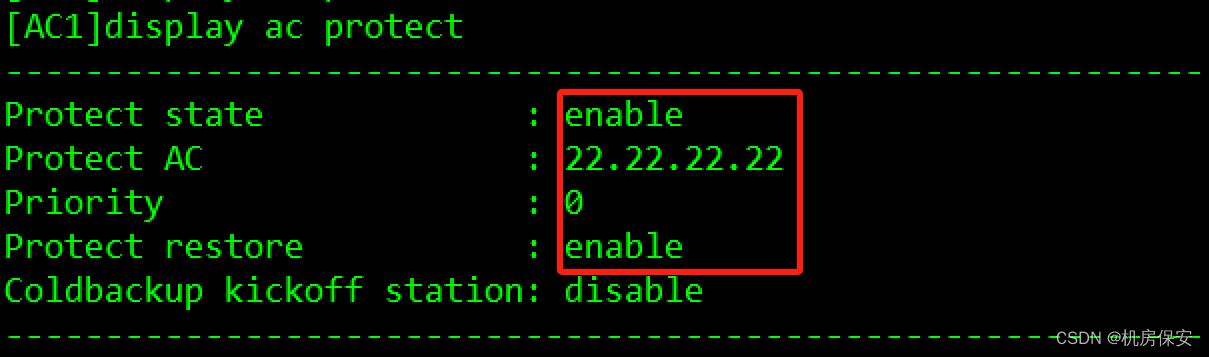
[AC1-wlan-view]ac protect enable
[AC1-wlan-view]ac protect protect-ac 22.22.22.22 priority 0
[AC1-wlan-view]ap-reset all
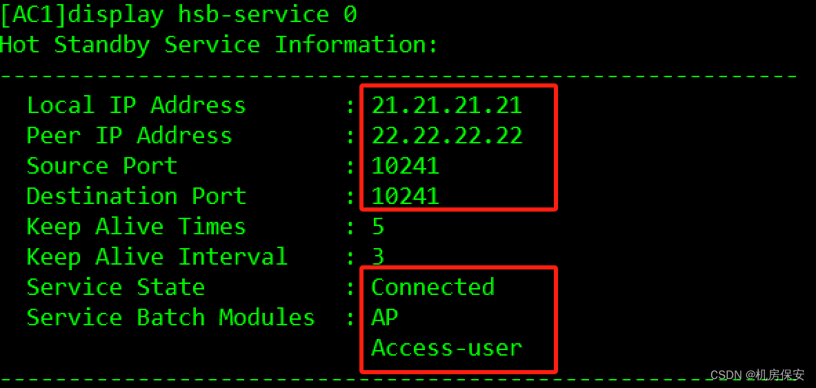
[AC1]hsb-service 0
[AC1-hsb-service-0]service-ip-port local-ip 21.21.21.21 peer-ip 22.22.22.22 local-data-port 10241 peer-data-port 10241
[AC1]hsb-service-type ap hsb-service 0
[AC1]hsb-service-type access-user hsb-service 0
#AC2
[AC2]wlan
[AC2-wlan-view]ac protect enable
[AC2-wlan-view]ac protect protect-ac 21.21.21.21 priority 1
[AC2-wlan-view]ap-reset all
[AC2]hsb-service 0
[AC2-hsb-service-0]service-ip-port local-ip 22.22.22.22 peer-ip 21.21.21.21 local-data-port 10241 peer-data-port 10241
[AC2]hsb-service-type ap hsb-service 0
[AC2]hsb-service-type access-user hsb-service 0验证:


3.3.6 安全策略部署
3.3.6.1 总部内互访安全策略部署
- 划分安全区域,将VLANIF 203接口划分进TrustZone,GE1/0/2接口划分进UntrustZone,GE1/0/3接口划分进DMZZone。
- 为了让FTP服务器能够被内部PC访问,在防火墙上创建安全策略FTP,仅允许内部FTP终端访问FTP服务器。
配置过程:
#FW1
[FW1]firewall zone trust
[FW1-zone-trust]add interface Vlanif 203
[FW1]firewall zone untrust
[FW1-zone-untrust]add interface GigabitEthernet 1/0/2
[FW1]firewall zone dmz
[FW1-zone-dmz]add interface GigabitEthernet 1/0/3
[FW1]security-policy
[FW1-policy-security]rule name FTP
[FW1-policy-security-rule-FTP]source-zone trust
[FW1-policy-security-rule-FTP]source-zone untrust
[FW1-policy-security-rule-FTP]destination-zone dmz
[FW1-policy-security-rule-FTP]source-address 192.168.100.0 mask 255.255.255.0
[FW1-policy-security-rule-FTP]source-address 10.1.37.2 mask 255.255.255.255
[FW1-policy-security-rule-FTP]destination-address 192.168.20.254 mask 255.255.255.0
[FW1-policy-security-rule-FTP]action permit
3.3.6.2 总部与分公司互通安全策略部署
- 为了实现总部与分公司网络的互通,在防火墙上创建安全策略Branch_1,允许总部的PC与分公司1的PC进行通信,同时分公司1的FTP终端也能够访问总部的FTP服务器。
配置过程:
#FW1
[FW1]security-policy
[FW1-policy-security]rule name Branch_1
[FW1-policy-security-rule-Branch_1]source-zone local
[FW1-policy-security-rule-Branch_1]source-zone trust
[FW1-policy-security-rule-Branch_1]source-zone untrust
[FW1-policy-security-rule-Branch_1]destination-zone local
[FW1-policy-security-rule-Branch_1]destination-zone trust
[FW1-policy-security-rule-Branch_1]destination-zone untrust
[FW1-policy-security-rule-Branch_1]source-address 192.168.100.0 mask 255.255.255.0
[FW1-policy-security-rule-Branch_1]source-address 200.1.11.2 mask 255.255.255.255
[FW1-policy-security-rule-Branch_1]source-address 10.1.37.0 mask 255.255.255.0
[FW1-policy-security-rule-Branch_1]destination-address 192.168.100.0 mask 255.255.255.0
[FW1-policy-security-rule-Branch_1]destination-address 200.1.11.1 mask 255.255.255.255
[FW1-policy-security-rule-Branch_1]destination-address 10.1.37.0 mask 255.255.255.0
[FW1-policy-security-rule-Branch_1]action permit
[FW1]interface GigabitEthernet 1/0/2
[FW1-GigabitEthernet1/0/2]service-manage ping permit
验证:配置完MPLS VPN之后回来验证
3.4 ISP网络部署
3.4.1 VLAN规划与部署
ISP网络的VLAN规划如Table 3-3所示。
注:为了保证网络的连通性,以及避免二层环路隐患,交换机端口只允许规定的VLAN通过, 多余的VLAN通过将影响整体网络稳定性评估。
3.4.2 IP地址规划及配置
IP地址规划如Table3-1 IP地址规划表所示,请按照规划正确配置IP地址。
配置过程:
#AR1
[AR1]interface LoopBack 0
[AR1-LoopBack0]ip address 1.1.1.1 32
[AR1]interface GigabitEthernet 0/0/0
[AR1-GigabitEthernet0/0/0]ip address 200.1.11.1 30
[AR1]interface GigabitEthernet 0/0/1
[AR1-GigabitEthernet0/0/1]ip address 200.1.12.1 30

#AR2
[AR2]interface LoopBack 0
[AR2-LoopBack0]ip address 2.2.2.2 32
[AR2]interface GigabitEthernet 0/0/0
[AR2-GigabitEthernet0/0/0]ip address 200.1.12.2 30
[AR2]interface GigabitEthernet 0/0/1
[AR2-GigabitEthernet0/0/1]ip address 200.1.23.1 30

#AR3
[AR3]interface LoopBack 0
[AR3-LoopBack0]ip address 3.3.3.3 32
[AR3]interface GigabitEthernet 0/0/0
[AR3-GigabitEthernet0/0/0]ip address 200.1.23.2 30
[AR3]interface GigabitEthernet 0/0/1
[AR3-GigabitEthernet0/0/1]ip address 200.1.34.1 30

#AR4
[AR4]interface LoopBack 0
[AR4-LoopBack0]ip address 4.4.4.4 32
[AR4]interface GigabitEthernet 0/0/0
[AR4-GigabitEthernet0/0/0]ip address 200.1.34.2 30
[AR4]interface GigabitEthernet 0/0/1
[AR4-GigabitEthernet0/0/1]ip address 200.1.45.1 30

#AR5
[AR5]interface LoopBack 0
[AR5-LoopBack0]ip address 5.5.5.5 32
[AR5]interface GigabitEthernet 0/0/0
[AR5-GigabitEthernet0/0/0]ip address 200.1.45.2 30
[AR5]interface GigabitEthernet 0/0/1
[AR5-GigabitEthernet0/0/1]ip address 200.1.25.1 30
3.4.3 ISP1网络中间系统-中间系统部署
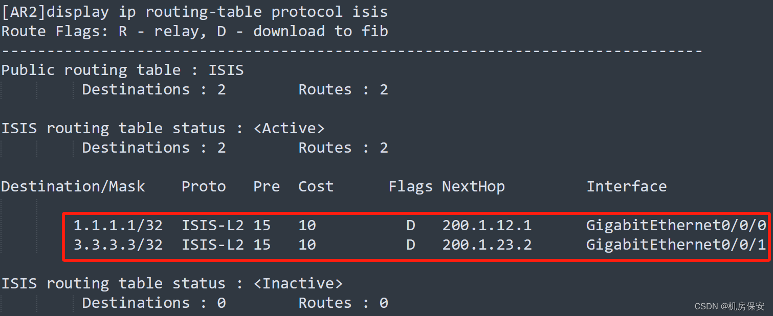
- 同一ISP区域内的AR路由器之间的互连接口以及Loopback 0均使能协议。
- ISP1区域中AR1、AR2、AR3之间中间系统-中间系统进程号为10,区域为49.0001.设备System-id为0000.0000.000X(X是路由器编号),例如AR1的System-id为0000.0000.0001,所有路由器均为Level-2类型路由器。
- 为了实现网络的快速收敛,使路由器能够更快地检测到邻居状态变化。采用动态BFD特性,同时需指定最小发送和接受间隔为100ms,本地检测时间倍数为4。
配置过程:
#AR1
[AR1]bfd
[AR1]isis 10
[AR1-isis-10]network-entity 49.0001.0000.0000.0001.00
[AR1-isis-10]is-level level-2
[AR1-isis-10]bfd all-interfaces enable
[AR1]interface LoopBack 0
[AR1-LoopBack0]isis enable 10
[AR1]interface GigabitEthernet 0/0/1
[AR1-GigabitEthernet0/0/1]isis enable 10
[AR1-GigabitEthernet0/0/1]isis bfd enable
[AR1-GigabitEthernet0/0/1]isis bfd min-rx-interval 100 min-tx-interval 100 detect-multiplier 4

#AR2
[AR2]bfd
[AR2]isis 10
[AR2-isis-10]network-entity 49.0001.0000.0000.0002.00
[AR2-isis-10]is-level level-2
[AR2-isis-10]bfd all-interfaces enable
[AR2]interface LoopBack 0
[AR2-LoopBack0]isis enable 10
[AR2]interface GigabitEthernet 0/0/0
[AR2-GigabitEthernet0/0/0]isis enable 10
[AR2-GigabitEthernet0/0/0]isis bfd enable
[AR2-GigabitEthernet0/0/0]isis bfd min-rx-interval 100 min-tx-interval 100 detect-multiplier 4
[AR2]interface GigabitEthernet 0/0/1
[AR2-GigabitEthernet0/0/1]isis enable 10
[AR2-GigabitEthernet0/0/1]isis bfd enable
[AR2-GigabitEthernet0/0/1]isis bfd min-rx-interval 100 min-tx-interval 100 detect-multiplier 4

#AR3
[AR3]bfd
[AR3]isis 10
[AR3-isis-10]network-entity 49.0001.0000.0000.0003.00
[AR3-isis-10]is-level level-2
[AR3-isis-10]bfd all-interfaces enable
[AR3]interface LoopBack 0
[AR3-LoopBack0]isis enable 10
[AR3]interface GigabitEthernet 0/0/0
[AR3-GigabitEthernet0/0/0]isis enable 10
[AR3-GigabitEthernet0/0/0]isis bfd enable
[AR3-GigabitEthernet0/0/0]isis bfd min-rx-interval 100 min-tx-interval 100 detect-multiplier 4
验证:

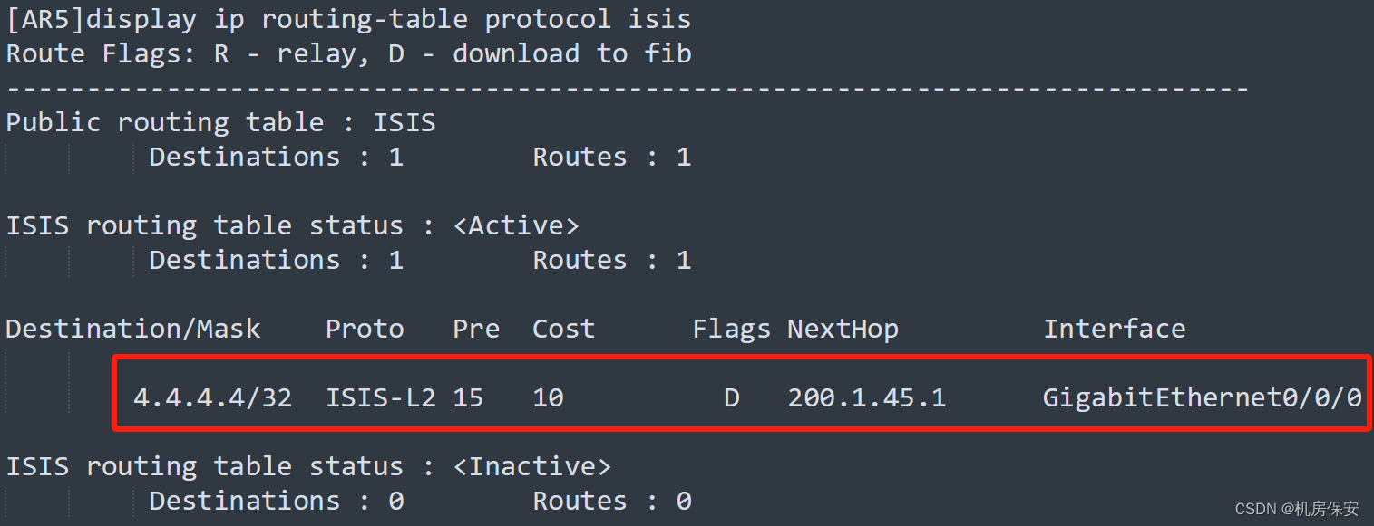
3.4.4 ISP2网络中间系统-中间系统部署
- 同一ISP区域内的AR路由器之间的互连接口以及Loopback 0均使能协议。
- ISP2区域中的AR4和AR5之间的互连接口以及Loopback 0也使能协议。
- ISP2区域中AR4、AR5之间中间系统-中间系统进程号为20,区域为49.0002.设备System-id为0000.0000.000X(X是路由器编号),例如AR1的System-id为0000.0000.0001,所有路由器均为Level-2类型路由器。
- 为了实现网络的快速收敛,使路由器能够更快地检测到邻居状态变化。采用动态BFD特性,同时需指定最小发送和接受间隔为100ms,本地检测时间倍数为4。
配置过程:
#AR4
[AR4]bfd
[AR4]isis 20
[AR4-isis-20]network-entity 49.0002.0000.0000.0004.00
[AR4-isis-20]is-level level-2
[AR4-isis-20]bfd all-interfaces enable
[AR4]interface LoopBack 0
[AR4-LoopBack0]isis enable 20
[AR4]interface GigabitEthernet 0/0/1
[AR4-GigabitEthernet0/0/1]isis enable 20
[AR4-GigabitEthernet0/0/1]isis bfd enable
[AR4-GigabitEthernet0/0/1]isis bfd min-rx-interval 100 min-tx-interval 100 detect-multiplier 4

#AR5
[AR5]bfd
[AR5]isis 20
[AR5-isis-20]network-entity 49.0002.0000.0000.0005.00
[AR5-isis-20]is-level level-2
[AR5-isis-20]bfd all-interfaces enable
[AR5]interface LoopBack 0
[AR5-LoopBack0]isis enable 20
[AR5]interface GigabitEthernet 0/0/0
[AR5-GigabitEthernet0/0/0]isis enable 20
[AR5-GigabitEthernet0/0/0]isis bfd enable
[AR5-GigabitEthernet0/0/0]isis bfd min-rx-interval 100 min-tx-interval 100 detect-multiplier 4
验证:

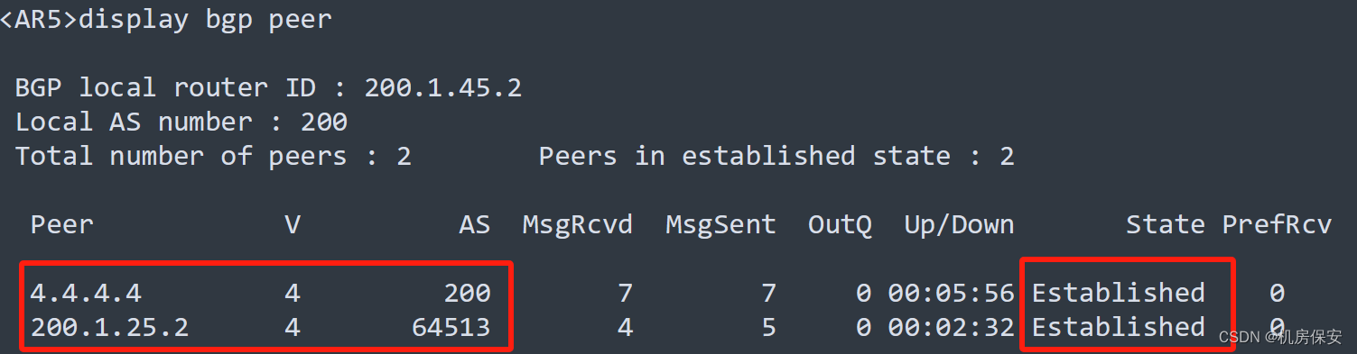
3.4.5 总部ISP1/ISP2 BGP部署
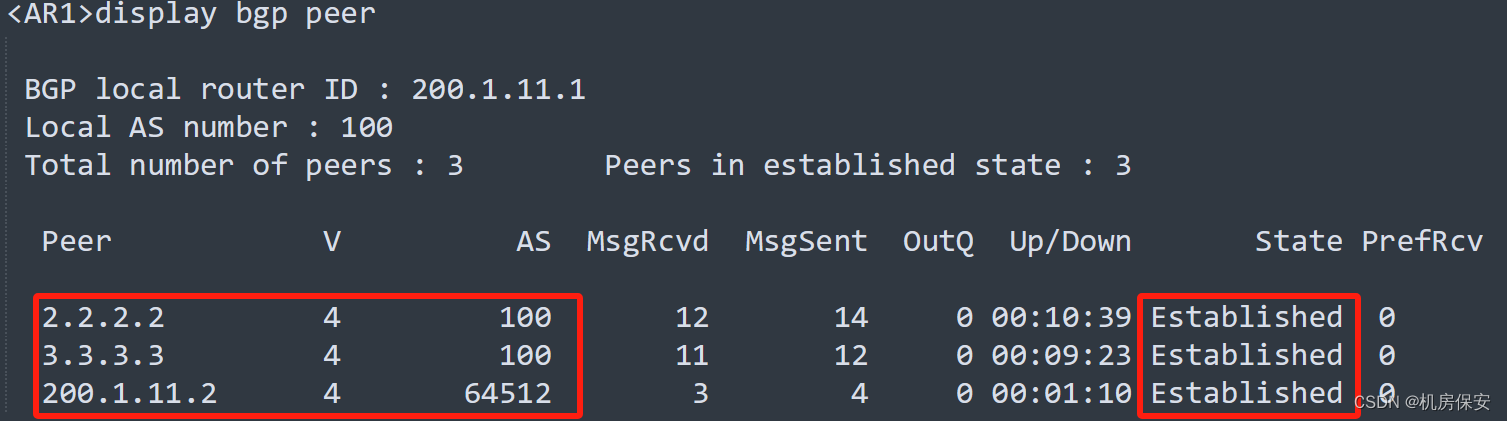
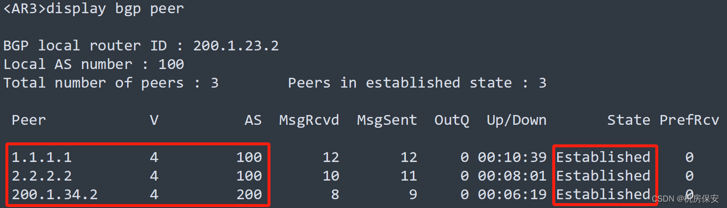
- ISP内的全部路由器运行BGP,其中AR1、AR2、AR3使用Loopback 0建立full-mesh的IBGP邻居关系,其BGP AS号为100。
- AR4和AR5为IBGP邻居关系,且使用Loopback 0建立IBGP邻居关系,AS号为200。
- AR3和AR4通过直连接口建立EBGP邻居。
- AR1和FW1、AR5和FW2为EBGP邻居,通过直连接口建立EBGP邻居,其中FW1的AS号为64512,FW2的AS号为64513。
配置过程:
#AR1
[AR1]bgp 100
[AR1-bgp]peer 2.2.2.2 as-number 100
[AR1-bgp]peer 3.3.3.3 as-number 100
[AR1-bgp]peer 200.1.11.2 as-number 64512
[AR1-bgp]peer 2.2.2.2 connect-interface LoopBack 0
[AR1-bgp]peer 3.3.3.3 connect-interface LoopBack 0

#AR2
[AR2]bgp 100
[AR2-bgp]peer 1.1.1.1 as-number 100
[AR2-bgp]peer 3.3.3.3 as-number 100
[AR2-bgp]peer 1.1.1.1 connect-interface LoopBack 0
[AR2-bgp]peer 3.3.3.3 connect-interface LoopBack 0

#AR3
[AR3]bgp 100
[AR3-bgp]peer 1.1.1.1 as-number 100
[AR3-bgp]peer 2.2.2.2 as-number 100
[AR3-bgp]peer 200.1.34.2 as-number 200
[AR3-bgp]peer 1.1.1.1 connect-interface LoopBack 0
[AR3-bgp]peer 2.2.2.2 connect-interface LoopBack 0

#AR4
[AR4]bgp 200
[AR4-bgp]peer 5.5.5.5 as-number 200
[AR4-bgp]peer 5.5.5.5 connect-interface LoopBack 0
[AR4-bgp]peer 200.1.34.1 as-number 100

#AR5
[AR5]bgp 200
[AR5-bgp]peer 4.4.4.4 as-number 200
[AR5-bgp]peer 4.4.4.4 connect-interface LoopBack 0
[AR5-bgp]peer 200.1.25.2 as-number 64513

#FW1
[FW1]bgp 64512
[FW1-bgp]peer 200.1.11.1 as-number 100

#FW2
[FW2]bgp 64513
[FW2-bgp]peer 200.1.25.1 as-number 200
验证:
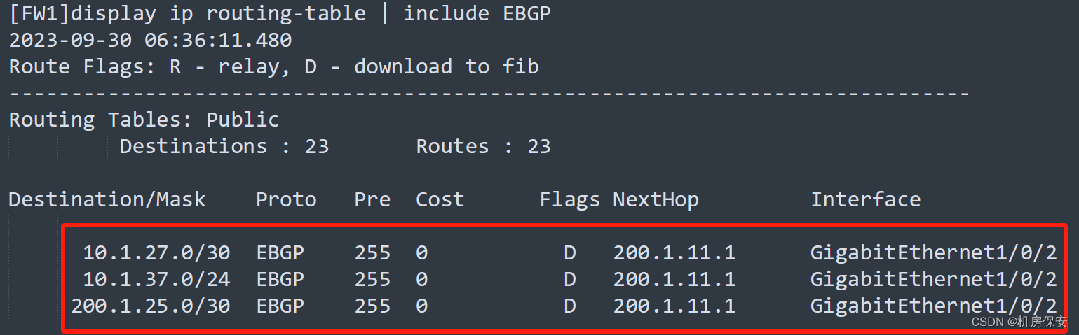
3.4.6 ISP1/ISP2 MPLS BGP VPN部署
- ISP1与ISP2之间使用BGP MPLS VPN Option B方案来实现路由互通。
- ISP内通过LDP协议实现标签分发,其中LSR-ID为各设备Loopback0地址。
- 总部和分公司都属于同一个VPN实例,名称为ict2020,总部和分支机构的RD值为100:1,出入RT值为100:1.
- 在全部的CE设备上只将必要的路由条目引入BGP,保证各公司的FTP终端能够访问总部FTP服务器。
配置过程:
MPLS配置
#AR1
[AR1]mpls lsr-id 1.1.1.1
[AR1]mpls
[AR1]mpls ldp
[AR1]interface GigabitEthernet 0/0/1
[AR1-GigabitEthernet0/0/1]mpls
[AR1-GigabitEthernet0/0/1]mpls ldp

#AR2
[AR2]mpls lsr-id 2.2.2.2
[AR2]mpls
[AR2]mpls ldp
[AR2]interface GigabitEthernet 0/0/0
[AR2-GigabitEthernet0/0/0]mpls
[AR2-GigabitEthernet0/0/0]mpls ldp
[AR2]interface GigabitEthernet 0/0/1
[AR2-GigabitEthernet0/0/1]mpls
[AR2-GigabitEthernet0/0/1]mpls ldp

#AR3
[AR3]mpls lsr-id 3.3.3.3
[AR3]mpls
[AR3]mpls ldp
[AR3]interface GigabitEthernet 0/0/0
[AR3-GigabitEthernet0/0/0]mpls
[AR3-GigabitEthernet0/0/0]mpls ldp
[AR3]interface GigabitEthernet 0/0/1
[AR3-GigabitEthernet0/0/1]mpls

#AR4
[AR4]mpls lsr-id 4.4.4.4
[AR4]mpls
[AR4]mpls ldp
[AR4]interface GigabitEthernet 0/0/1
[AR4-GigabitEthernet0/0/1]mpls
[AR4-GigabitEthernet0/0/1]mpls ldp
[AR4]interface GigabitEthernet 0/0/0
[AR4-GigabitEthernet0/0/0]mpls

#AR5
[AR5]mpls lsr-id 5.5.5.5
[AR5]mpls
[AR5]mpls ldp
[AR5]interface GigabitEthernet 0/0/0
[AR5-GigabitEthernet0/0/0]mpls
[AR5-GigabitEthernet0/0/0]mpls ldp

Option B配置
#AR1
[AR1]ip vpn-instance ict2020
[AR1-vpn-instance-ict2020]route-distinguisher 100:1
[AR1-vpn-instance-ict2020-af-ipv4]vpn-target 100:1 both
[AR1]interface GigabitEthernet 0/0/0
[AR1-GigabitEthernet0/0/0]ip binding vpn-instance ict2020
[AR1-GigabitEthernet0/0/0]ip address 200.1.11.1 30
[AR1]bgp 100
[AR1-bgp]ipv4-family vpn-instance ict2020
[AR1-bgp-ict2020]peer 200.1.11.2 as-number 64512
[AR1-bgp]ipv4-family vpnv4
[AR1-bgp-af-vpnv4]peer 3.3.3.3 enable
[AR1-bgp-af-vpnv4]peer 3.3.3.3 next-hop-local

#AR3
[AR3]bgp 100
[AR3-bgp]ipv4-family vpnv4
[AR3-bgp-af-vpnv4]undo policy vpn-target
[AR3-bgp-af-vpnv4]peer 1.1.1.1 enable
[AR3-bgp-af-vpnv4]peer 1.1.1.1 next-hop-local
[AR3-bgp-af-vpnv4]peer 200.1.34.2 enable

#AR4
[AR4]bgp 200
[AR4-bgp]ipv4-family vpnv4
[AR4-bgp-af-vpnv4]undo policy vpn-target
[AR4-bgp-af-vpnv4]peer 5.5.5.5 enable
[AR4-bgp-af-vpnv4]peer 5.5.5.5 next-hop-local
[AR4-bgp-af-vpnv4]peer 200.1.34.1 enable

#AR5
[AR5]ip vpn-instance ict2020
[AR5-vpn-instance-ict2020]route-distinguisher 100:1
[AR5-vpn-instance-ict2020-af-ipv4]vpn-target 100:1 both
[AR5]interface GigabitEthernet 0/0/1
[AR5-GigabitEthernet0/0/1]ip binding vpn-instance ict2020
[AR5-GigabitEthernet0/0/1]ip address 200.1.25.1 30
[AR5]bgp 200
[AR5-bgp]ipv4-family vpn-instance ict2020
[AR5-bgp-ict2020]peer 200.1.25.2 as-number 64513
[AR5-bgp]ipv4-family vpnv4
[AR5-bgp-af-vpnv4]peer 4.4.4.4 enable
[AR5-bgp-af-vpnv4]peer 4.4.4.4 next-hop-local

CE路由引入
#FW1
[FW1]bgp 64512
[FW1-bgp]network 192.168.100.0 24
[FW1-bgp]network 192.168.20.0 24

#FW2
[FW2]bgp 64513
[FW2-bgp]network 10.1.37.0 24
验证:


3.5 分公司1网络部署
3.5.1 VLAN规划与部署
分公司1网络的VLAN规划如Teble3-3所示。
注:为了保证网络的连通性,以及避免二层环路隐患,交换机端口只允许规定的VLAN通过, 多余的VLAN通过将影响整体网络稳定性评估。
配置过程:
#SW5
[SW5]vlan batch 27 37
[SW5]interface GigabitEthernet 0/0/1
[SW5-GigabitEthernet0/0/1]port link-type access
[SW5-GigabitEthernet0/0/1]port default vlan 27
[SW5]port-group group-member GigabitEthernet 0/0/2 GigabitEthernet 0/0/3
[SW5-port-group]port link-type access
[SW5-port-group]port default vlan 37
3.5.2 IP地址规划及配置
IP地址规划如Table 3-1IP地址规划表所示,请按照规划正确配置IP地址。
配置过程:
#FW2
[FW2]interface GigabitEthernet 1/0/0
[FW2-GigabitEthernet1/0/0]ip address 200.1.25.2 30
[FW2]interface GigabitEthernet 1/0/1
[FW2-GigabitEthernet1/0/1]ip address 10.1.27.1 30
#SW5
[SW5]interface Vlanif 27
[SW5-Vlanif27]ip address 10.1.27.2 30
[SW5]interface vlanif 37
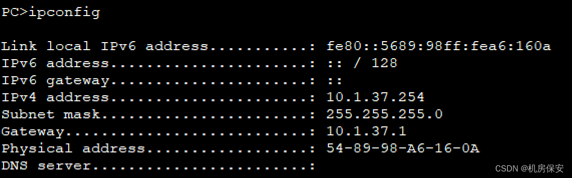
[SW5-Vlanif37]ip address 10.1.37.1 243.5.3 DHCP地址池部署
- 在SW5上通过接口模式部署DHCP地址池,为分公司1内的PC提供服务。
- DHCP地址池的网段为10.1.37.0/24,网关地址为10.1.37.1,排除地址10.1.37.2。
配置过程:
#S5
[SW5]dhcp enable
[SW5]interface Vlanif 37
[SW5-Vlanif37]dhcp select interface
[SW5-Vlanif37]dhcp server excluded-ip-address 10.1.37.2
验证:
3.5.4 静态路由部署
- 通过配置静态路由的方式内部的,保证分公司1内部的PC和FTP终端能够访问总部网络。
配置过程:
#FW1
[FW2]ip route-static 0.0.0.0 0 200.1.25.1
[FW2]ip route-static 10.1.37.0 24 10.1.27.2

#SW5
[SW5]ip route-static 0.0.0.0 0 10.1.27.1
3.5.5 安全策略部署
3.3.5.1 分公司与总部网络互通安全策略部署
配置过程:
#FW2
[FW2]security-policy
[FW2-policy-security]rule name Branch_1
[FW2-policy-security-rule-Branch_1]source-zone local
[FW2-policy-security-rule-Branch_1]source-zone trust
[FW2-policy-security-rule-Branch_1]source-zone untrust
[FW2-policy-security-rule-Branch_1]destination-zone local
[FW2-policy-security-rule-Branch_1]destination-zone trust
[FW2-policy-security-rule-Branch_1]destination-zone untrust
[FW2-policy-security-rule-Branch_1]source-address 192.168.100.0 mask 255.255.255.0
[FW2-policy-security-rule-Branch_1]source-address 200.1.25.2 mask 255.255.255.255
[FW2-policy-security-rule-Branch_1]source-address 10.1.27.0 mask 255.255.255.0
[FW2-policy-security-rule-Branch_1]source-address 10.1.37.0 mask 255.255.255.0
[FW2-policy-security-rule-Branch_1]destination-address 192.168.100.0 mask 255.255.255.0
[FW2-policy-security-rule-Branch_1]destination-address 200.1.25.1 mask 255.255.255.255
[FW2-policy-security-rule-Branch_1]destination-address 10.1.27.0 mask 255.255.255.0
[FW2-policy-security-rule-Branch_1]destination-address 10.1.37.0 mask 255.255.255.0
[FW2-policy-security-rule-Branch_1]action permit
[FW2]interface GigabitEthernet 1/0/0
[FW2-GigabitEthernet1/0/0]service-manage ping permit
[FW2]interface GigabitEthernet 1/0/1
[FW2-GigabitEthernet1/0/1]service-manage ping permit