UFS 13 - Logical Unit Management
基于UFS 3.1 标准文档阐述
UFS 1-UFS架构简介1
UFS 2 -UFS架构简介2
UFS 3 - UFS RPMB
UFS 4 - UFS Boot
UFS 5 - UFS UIC Layer: MIPI M-PHY
UFS 6 - UAP – SCSI Commands(1)
UFS 7 - UAP – SCSI Commands(2)
UFS 8 - UAP – SCSI Commands(3)
UFS 9 - UAP – SCSI Commands(4)
UFS 10 - UAP – SCSI Commands(5)
UFS 11 - UFS RPMB分区功能验证
UFS 12 - UAP – SCSI Commands(6)
1 Introduction
The functionality aims to provide a mechanism to let an external application define and use a virtual memory organization which could easily fit different usage models in a versatile way.
该功能旨在提供一种机制,让外部应用程序定义和使用虚拟内存组织,该组织可以轻松地以多种方式适应不同的使用模型。
Besides segmenting the available addressable space, the mechanism introduces the possibility of differentiating each logical unit through dedicated functionalities and features.
除了对可用的可寻址空间进行分段之外,该机制还引入了通过专用功能和特性来区分每个逻辑单元的可能性。
This section describes the procedure to configure the UFS device in terms of: number of logical units, logical unit size, logical unit memory type, etc. Security features can be configured as described in clause 12, UFS Security.
本节从以下方面描述配置 UFS 设备的过程:逻辑单元数量、逻辑单元大小、逻辑单元内存类型等。安全功能可以按照第 12 条“UFS 安全”中的描述进行配置。
A UFS device can be organized in different logical units. Each one represents an autonomous computing entity with independent logical address ranges and singularly accessible.
UFS 设备可以组织为不同的逻辑单元。每一个都代表一个具有独立逻辑地址范围且可单独访问的自治计算实体。
Moreover, each logical unit can be defined for a specified use and with peculiar attributes (i.e., memory type) in order to be adapted to different UFS host usage models and operating systems requirements.
此外,每个逻辑单元可以针对指定用途进行定义,并具有特定的属性(即内存类型),以便适应不同的 UFS 主机使用模型和操作系统要求。
2 Logical Unit features
UFS device address space is organized in several memory areas configurable by the user. In particular, such memory areas are denoted as logical units and characterized by the fact that they have independent logical addressable spaces starting from the logical address zero.
UFS 设备地址空间组织在多个可由用户配置的存储区域中。特别地,这样的存储器区域被表示为逻辑单元并且其特征在于它们具有从逻辑地址零开始的独立的逻辑可寻址空间。
In addition to the logical units, the UFS device supports the following well known logical units for specific purposes: UFS Device, REPORT LUNS, Boot and RPMB. Logical units are addressed by the LUN (logical unit number), while well known logical unit are addressed by the W-LUN (well known logical unit number).
除了逻辑单元之外,UFS 设备还支持以下用于特定用途的众所周知的逻辑单元:UFS 设备、REPORT LUN、Boot 和 RPMB。逻辑单元由LUN(逻辑单元号)寻址,而众所周知的逻辑单元由W-LUN(众所周知的逻辑单元号)寻址。
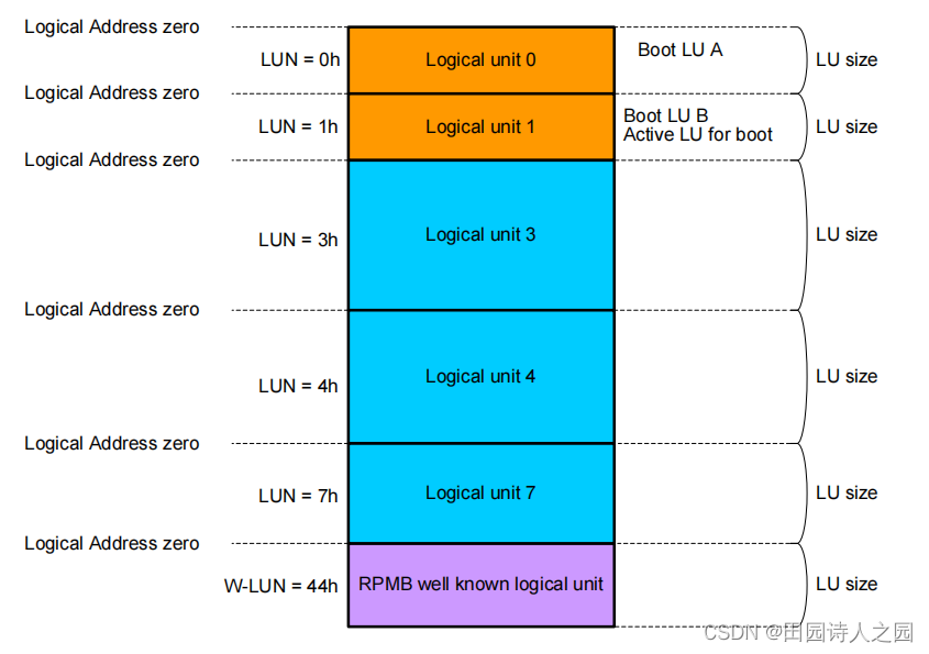
NOTE 1 The figure shows an example of device configuration in which LU 0 and LU 1 are used as boot logical units, and the logical units 3, 4 and 7 for code and data storage. LU 1 is the boot active logical unit and it may be accessed in read using the W-LUN = 30h (LUN field in UPIU = B0h).
注: 该图显示了设备配置示例,其中 LU 0 和 LU 1 用作引导逻辑单元,逻辑单元 3、4 和 7 用于代码和数据存储。 LU 1 是引导活动逻辑单元,可以使用 W-LUN = 30h(UPIU 中的 LUN 字段 = B0h)以读取方式对其进行访问。
Each logical unit will have a physical implementation on the non-volatile storage media.
每个逻辑单元将在非易失性存储介质上具有物理实现。
In particular, the UFS device shall support:
特别是,UFS 设备应支持:
- The number of logical units specified by bMaxNumberLU. Each of them configurable as boot logical units with a maximum of two.
- bMaxNumberLU 指定的逻辑单元数。它们中的每一个都可配置为引导逻辑单元,最多有两个。
- One RPMB well known logical unit (W-LUN = 44h, LUN field in UPIU = C4h). RPMB well known logical unit may be further configured into up to four separate RPMB regions (RPMB region 0 - RPMB region 3).
- 1 个 RPMB 众所周知的逻辑单元(W-LUN = 44h,UPIU 中的 LUN 字段 = C4h)。 RPMB众所周知的逻辑单元可以进一步被配置成多达四个单独的RPMB区域(RPMB区域0-RPMB区域3)。
Two logical units can be configured as boot logical unit, with only one of them active and readable through the Boot well known logical unit (W-LUN = 30h) for the execution of the system boot (see 13.1, UFS Boot). The RPMB well known logical unit is accessed by authenticated operations by a well defined security algorithm (see 12.4, RPMB). The other logical units will be used to fulfill other use cases.
可以将两个逻辑单元配置为引导逻辑单元,其中只有一个逻辑单元处于活动状态并可通过引导众所周知的逻辑单元 (W-LUN = 30h) 进行读取,以执行系统引导(请参阅 13.1,UFS 引导)。 RPMB 众所周知的逻辑单元由经过明确定义的安全算法(参见 12.4,RPMB)的认证操作进行访问。其他逻辑单元将用于完成其他用例。
Common features of each logical unit are:
- independent logical addressable spaces (starting from logical address zero up to the logical unit size),
- Configurable logical unit size.
The size of each logical unit is determined by the number of allocation units assigned to it:
dNumAllocUnits parameter value of the Configuration Descriptor. The dNumAllocUnits is expressed in terms of allocation unit size (bAllocationUnitSize).
Moreover each logical unit is characterized by the memory type parameter which can be configured.
Examples of memory types to differentiate logical unit properties are the following ones: - Default type – regular memory characteristic
- System Code type – a logical unit that is rarely updated (e.g., system files or binary code executable files or the host operating system image and other system data structures)
- Non-Persistent type – a logical unit that is used for temporary information (e.g., swap file extend the host virtual memory space)
- Enhanced Memory type – vendor specific attribute
The definition of the Enhanced Memory type is left open in order to accomplish different needs and vendor specific implementations.
Mechanisms of write protection can be configured for each logical unit. Write protection feature types are: - Permanent write protection (permanent read only)
- Power on write protection (write protection can be cleared with a power cycle or a hardware reset event)
Write protection is not available in the RPMB well known logical unit.
3 Logical Unit Configuration
The user shall configure the logical units of the UFS device according to the following rules:
- Maximum number of logical units is specified by bMaxNumberLU
- One or two logical units can be configured as boot logical units.
When a UFS device is shipped only the following well known logical units will be available: UFS Device, REPORT LUNS and the RPMB. All other logical units shall be configured before they can be accessed.
The RPMB well known logical unit shall be configured by the device manufacturer before shipping the device. Only RPMB region 0 shall be enabled and bRPMBRegion0Size shall be set to the same size as the total RPMB well known logical unit size before shipping the device.
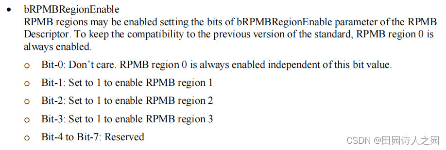
Logical units and RPMB regions may be configured writing the Configuration Descriptors, see 14.1.3, Accessing Descriptors and Device Configuration, for details. RPMB regions may be configured multiple times until the Configuration Descriptor is locked by setting bConfigDescrLock attribute value to 01h. RPMB key may be programmed any time when the target RPMB region is enabled, and may be programmed independent to whether the value of bConfigDescrLock attribute is set or not. When RPMB regions are re-configured with different configuration setting, the data which was previously written to any RPMB region shall be erased while RPMB key and RPMB write counter are maintained. To keep the compatibility to the previous version of the standard, RPMB region 0 is always enabled independent of 5493
configuration value of bRPMBRegionEnable.
The configuration of each logical unit and the configuration of RPMB regions may be retrieved by reading the corresponding Unit Descriptor.
It is recommended to execute logical unit configuration and RPMB region configuration during the system manufacturing phase.
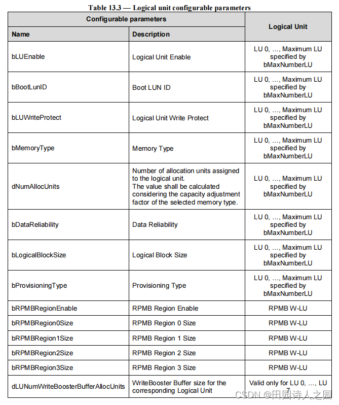
Table 13.3 summarizes the configurable parameters per logical unit. See 14.1.4, Descriptor Definitions, for details about these parameters.
The following Geometry Descriptor parameters provide relevant information for configuring the logical units:
- qTotalRawDeviceCapacity (total raw device density in unit of 512 bytes)
- dSegmentSize
- bAllocationUnitSize (Allocation Unit Size, value expressed in number of segments)
- wSupportedMemoryTypes
- Maximum number of allocation unit for each memory type (dSystemCodeMaxNAllocU, dNonPersistMaxNAllocU, etc.)
- Capacity Adjustment Factor for each memory type (wSystemCodeCapAdjFac, wNonPersistCapAdjFac, etc.)
- bMinAddrBlockSize (this parameter indicates a value equal or greater than 4Kbyte)
- bOptimalReadBlockSize and bOptimalWriteBlockSize
- bMaxInBufferSize
- bMaxOutBufferSize
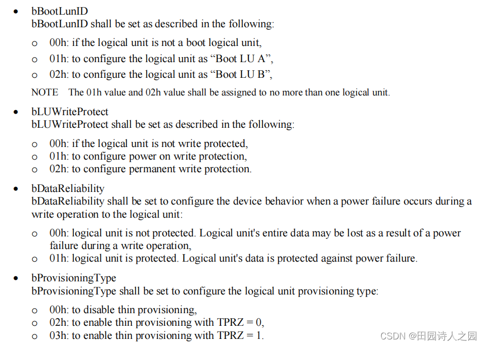
To enable the access to a logical unit, the user shall configure Unit Descriptor parameters as described in the following: - bLUEnable
bLUEnable shall be set to 01h to enable the logical unit. If bLUEnable is equal to 00h the logical unit is disabled and all Unit Descriptor parameters are don’t care. - bMemoryType
bMemoryType shall be set to value corresponding to the desired memory type. The wSupportedMemoryTypes parameter in the Geometry Descriptor indicates which memory types are supported by the device. - bLogicalBlockSize
bLogicalBlockSize value shall adhere to the following rules:
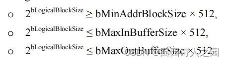
To optimize the device performance, it is recommended to configure the logical block size (bLogicalBlockSize) to represent the value indicated by dOptimalLogicalBlockSize for the specific logical unit memory type.
Supported bLogicalBlockSize values are device specific, refer to the vendor datasheet for further information. - dNumAllocUnits
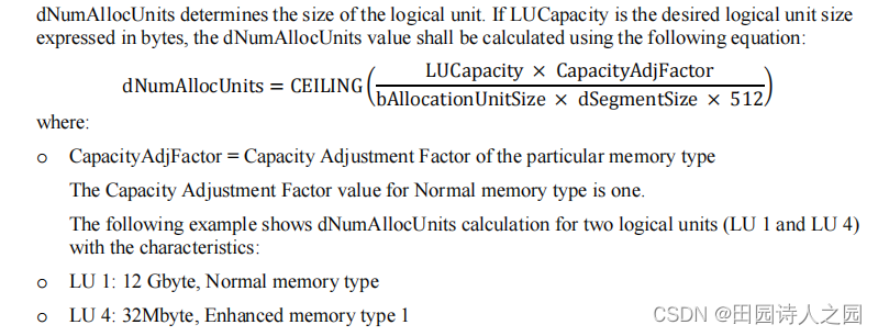
Assuming that the medium of the UFS device is composed by NAND flash memories which support 2 bit-per-cell and 1 bit-per-cell operation modes. The 2 bit-per-cell operation mode may be associated with the Normal memory type, while the 1 bit-per-cell operation mode may be associated with the Enhanced memory type 1.
The Capacity Adjustment Factor for the Enhanced memory type 1 will be equal to 2.
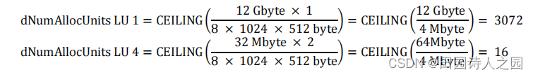
If:
o dSegmentSize = 1024
o bAllocationUnitSize = 8
Then dNumAllocUnits for LU 1 and LU 4 are:
The logical unit capacity can be retrieved by either reading the qLogicalBlockCount parameter in the Unit Descriptor or issuing the READ CAPACITY command.
In particular, the relations between the parameters returned by READ CAPACITY (RETURNED LOGICAL BLOCK ADDRESS and LOGICAL BLOCK LENGTH IN BYTES), and bLogicalBlockSize and qLogicalBlockCount parameters in Unit Descriptors are:

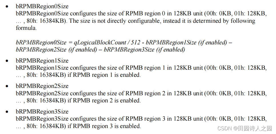
RPMB well known logical unit may be divided in multiple RPMB regions configuring the parameters described in the following.
The total size of the RPMB well known logical unit is indicated by qLogicalBlockCount of RPMB Unit Descriptor. An attempt to configure the device setting the RPMB regions with total size that exceeds the value indicated by qLogicalBlockCount shall fail. An attempt to configure the device setting a RPMB Region with enable bit to one and size to zero shall fail. An attempt to configure the device setting a RPMB Region with enable bit to zero and size greater than zero shall fail.