本文将尝试向您介绍 WebGPU 的基础知识。
在阅读本文之前,希望您应该已经对 mapping arrays, destructuring assignment, spreading values, async/await, es6 modules 有基础的了解,因为这些内容将在下文被广泛使用。
如果您已经了解 WebGL,请阅读此文 。
WebGPU 是一种 API,可让您执行 2 项基本操作。
- 绘制三角形/点/线到纹理
- 在 GPU 上运行计算
就这些!
之后关于 WebGPU 的一切都由你决定。这就像学习一种计算机语言,如 JavaScript、Rust 或 C++。首先,您学习基础知识,然后由您创造性地使用这些基础知识来解决您的问题。
WebGPU 是一个非常低级的 API。虽然您可以制作一些小示例,但对于许多应用程序而言,它可能需要大量代码和一些严格的数据组织。例如,支持 WebGPU 的 three.js 由约 600k 精简的 JavaScript 组成,而这只是它的基础库。这不包括加载程序、控件、后处理和许多其他功能。
关键是,如果您只想在屏幕上显示一些内容,最好选择一个提供大量代码的库,而这些代码是您自己将要编写的。
另一方面,也许您有一个自定义用例,或者您可能想要修改现有的库,或者您可能只是好奇它是如何工作的。如果是这些情况,请继续阅读!
1. 开始 Getting Started
很难决定从哪里开始。在某种程度上,WebGPU 是一个非常简单的系统。它所做的只是在 GPU 上运行 3 种类型的函数。顶点着色器 (Vertex Shaders)、片段着色器 (Fragment Shaders)、计算着色器 (Compute Shaders)。
A Vertex Shader computes vertices. The shader returns vertex positions. For every group of 3 vertices, it returns a triangle drawn between those 3 positions [1]
顶点着色器计算顶点。着色器返回顶点位置。每3 个顶点为1组,它返回在这 3 个位置之间绘制的三角形 [见注释1]
A Fragment Shader computes colors [2]. When a triangle is drawn, for each pixel to be drawn the GPU calls your fragment shader. The fragment shader then returns a color.
片段着色器计算颜色 [见注释2]。绘制三角形时,对于要绘制的每个像素,GPU 都会调用您的片段着色器。然后片段着色器返回一种颜色。
A Compute Shader is more generic. It’s effectively just a function you call and say “execute this function N times”. The GPU passes the iteration number each time it calls your function so you can use that number to do something unique on each iteration.
计算着色器更通用。它实际上只是一个你可以调用并命令其“执行这个函数 N 次”的函数。 GPU 每次调用您的函数时都会传递迭代编号,因此您可以使用该编号在每次迭代中做一些独特的事情。
If you squint hard, you can think of these functions similar to the functions to pass to array.forEach or array.map. The functions you run on the GPU are just functions, just like JavaScript functions. The part that differs is they run on the GPU, and so to run them you need to copy all the data you want them to access to the GPU in the form of buffers and textures and they only output to those buffers and textures. You need to specify in the functions which bindings or locations the function will look for the data. And, back in JavaScript, you need to bind the buffers and textures holding your data to the bindings or locations. Once you’ve done that you tell the GPU to execute the function.
如果你有些不太明白,可以把这些函数想成类似于传递给 array.forEach 或 array.map 的函数。你在 GPU 上运行的功能只是函数,就像 JavaScript 函数一样。不同的部分是它们在 GPU 上运行,为了要运行它们,需要将它们希望访问的所有数据以缓冲区和纹理的形式复制到 GPU,并且它们仅输出到这些缓冲区和纹理。需要在函数中指定函数将查找数据的绑定或位置。并且,回到 JavaScript 中,您需要将保存数据的缓冲区和纹理绑定到绑定或位置。完成后,您告诉 GPU 执行该函数。
也许图片会有所帮助。这是使用顶点着色器和片段着色器绘制三角形的 WebGPU 设置的简化图
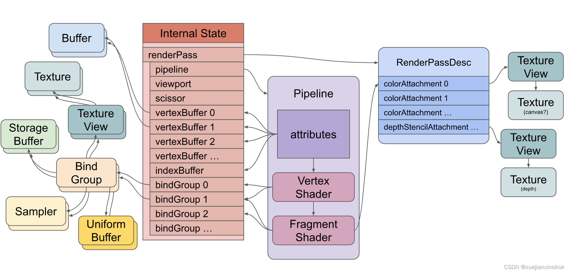
这张图需要注意什么
- 这是一个渲染管道。它包含 GPU 将运行的顶点着色器和片段着色器。您还可以拥有带计算着色器的管道。
- The shaders reference resources (buffers, textures, samplers)
indirectly through Bind Groups 着色器通过 绑定组 间接引用资源(缓冲区、纹理、采样器) - The pipeline defines attributes that reference buffers indirectly
through the internal state 管道定义了通过内部状态间接引用缓冲区的属性 - Attributes pull data out of buffers and feed the data into the vertex
shader. 属性从缓冲区中提取数据并将数据馈送到顶点着色器。 - The vertex shader may feed data into the fragment shader
顶点着色器可以将数据馈送到片段着色器 - The fragment shader writes to textures indirectly through the render
pass description 片段着色器通过渲染过程描述间接写入纹理
要在 GPU 上执行着色器,您需要创建所有这些资源并设置此状态。资源的创建相对简单。一件有趣的事情是大多数 WebGPU 资源在创建后无法更改。你可以改变它们的内容,但不能改变它们的大小、用途、格式等……如果你想改变任何东西,你可以创建一个新资源并销毁旧资源。
一些状态是通过创建命令缓冲区然后执行来设置的。命令缓冲区顾名思义。它们是命令缓冲区。您创建编码器。编码器将命令编码到命令缓冲区中。然后您完成编码器,它会为您提供它创建的命令缓冲区。然后,您可以提交该命令缓冲区,让 WebGPU 执行命令。
下面是一些编码命令缓冲区的伪代码,后面是创建的命令缓冲区的表示。
encoder = device.createCommandEncoder()
// draw something
{


  pass = encoder.beginRenderPass(...)
  pass.setPipeline(...)
  pass.setVertexBuffer(0, …)
  pass.setVertexBuffer(1, …)
  pass.setIndexBuffer(...)
  pass.setBindGroup(0, …)
  pass.setBindGroup(1, …)
  pass.draw(...)
  pass.end()
}
// draw something else
{


  pass = encoder.beginRenderPass(...)
  pass.setPipeline(...)
  pass.setVertexBuffer(0, …)
  pass.setBindGroup(0, …)
  pass.draw(...)
  pass.end()
}
// compute something
{


  pass = encoder.beginComputePass(...)
  pass.beginComputePass(...)
  pass.setBindGroup(0, …)
  pass.setPipeline(...)
  pass.dispatchWorkgroups(...)
  pass.end();
}
commandBuffer = encoder.finish();
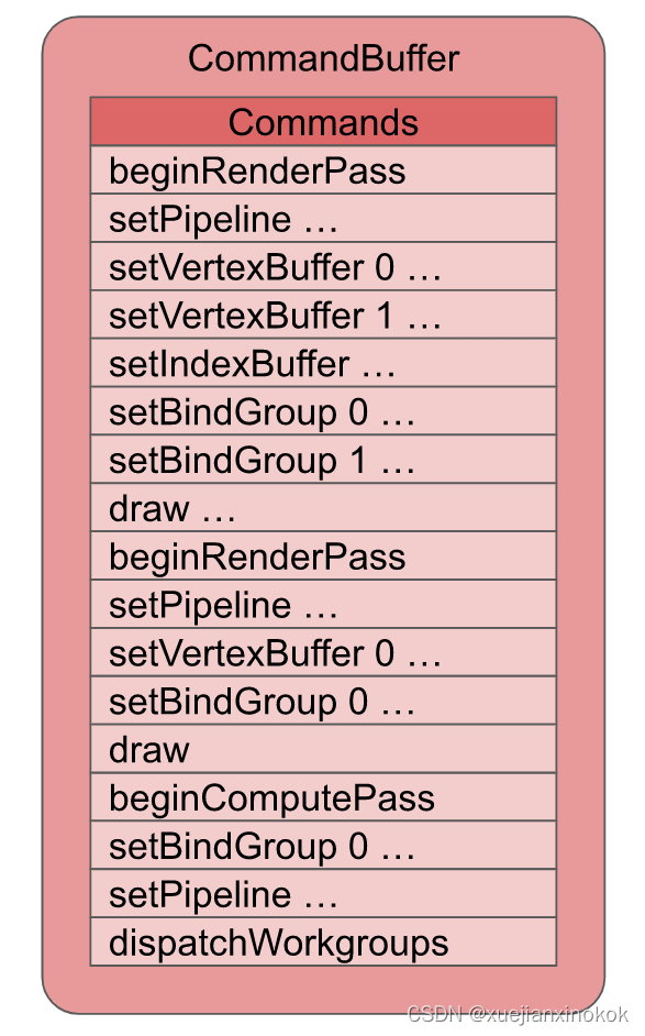
创建命令缓冲区后,您可以提交以执行
device.submit([commandBuffer]);
上图表示命令缓冲区中某些 draw 命令的状态。执行命令将设置内部状态,然后绘制命令将告诉 GPU 执行顶点着色器(并间接执行片段着色器)。 dispatchWorkgroup 命令将告诉 GPU 执行计算着色器。
我希望这给出了您需要设置的状态的一些概览。如上所述,WebGPU 有 2 个基本功能可以做
- 绘制三角形/点/线到纹理
- 在 GPU 上运行计算
我们将通过一个小例子来完成这些事情。其他文章将展示为这些东西提供数据的各种方式。请注意,这将是非常基本的。我们需要建立这些基础知识的基础。稍后我们将展示如何使用它们来做人们通常使用 GPU 做的事情,如 2D 图形、3D 图形等……
2. 绘制三角形到纹理 Drawing triangles to textures
WebGPU 可以绘制三角形到纹理。就本文而言,纹理是像素的二维矩形[见注释3] 。 元素表示网页上的纹理。在 WebGPU 中,我们可以向画布请求纹理,然后渲染到该纹理。
要使用 WebGPU 绘制三角形,我们必须提供 2 个“着色器”。同样,着色器是在 GPU 上运行的函数。这2个着色器是
-
Vertex Shaders
顶点着色器是计算绘制三角形/直线/点的顶点位置的函数 -
Fragment Shaders
片段着色器是在绘制三角形/线/点时计算要绘制/栅格化的每个像素的颜色(或其他数据)的函数
让我们从一个非常小的 WebGPU 程序开始画一个三角形。
我们需要一个画布来显示我们的三角形
<canvas></canvas>
然后我们需要一个 <script> 标签来保存我们的 JavaScript。
<canvas></canvas>
<script type="module">

... javascript goes here ...

</script>
下面的所有 JavaScript 都将放在这个脚本标签中
WebGPU 是一种异步 API,因此容易在异步函数中使用。我们首先请求适配器,然后从适配器请求设备。
async function main() {


  const adapter = await navigator.gpu?.requestAdapter();
  const device = await adapter?.requestDevice();
  if (!device) {


    fail('need a browser that supports WebGPU');
    return;
  }
}
main();
上面的代码是相当清楚的。首先,我们使用 ?. 可选链式运算符请求适配器。因此,如果 navigator.gpu 不存在,则 adapter 将是未定义的。如果它确实存在,那么我们将调用 requestAdapter 。它异步地转换结果,所以需要 await 。适配器代表一个特定的 GPU。有些设备有多个 GPU。
我们从适配器请求设备,但再次使用 ?. ,这样如果适配器碰巧未定义,那么设备也将是未定义的。
如果未设置 device ,则可能是用户使用的是旧版本浏览器(chrome>=113 才支持WebGPU)。
接下来我们查找画布并为其创建一个 webgpu 上下文。这将使我们获得一个纹理来渲染,该纹理将用于渲染网页中的画布。
  // Get a WebGPU context from the canvas and configure it
  const canvas = document.querySelector('canvas');
  const context = canvas.getContext('webgpu');
  const presentationFormat = navigator.gpu.getPreferredCanvasFormat();
  context.configure({


    device,
    format: presentationFormat,
  });
同样,上面的代码也很清晰。我们从画布中获得了一个 “webgpu” 上下文。我们询问系统首选的画布格式是什么。这将是 “rgba8unorm” 或 “bgra8unorm” 。它是什么并不重要,但通过查询 它将使用户系统的速度最快的格式。
我们通过调用 configure 将其作为 format 传递到 webgpu 画布上下文中。我们还传入了 device ,它将此画布与我们刚刚创建的设备相关联。
接下来我们创建一个着色器模块。着色器模块包含一个或多个着色器函数。在我们的例子中,我们将编写 1 个顶点着色器函数和 1 个片段着色器函数。
  const module = device.createShaderModule({


    label: 'our hardcoded red triangle shaders',
    code: `
      @vertex fn vs(
        @builtin(vertex_index) vertexIndex : u32
      ) -> @builtin(position) vec4f {
        var pos = array<vec2f, 3>(
          vec2f( 0.0,  0.5),  // top center
          vec2f(-0.5, -0.5),  // bottom left
          vec2f( 0.5, -0.5)   // bottom right
        );

        return vec4f(pos[vertexIndex], 0.0, 1.0);
      }

      @fragment fn fs() -> @location(0) vec4f {
        return vec4f(1.0, 0.0, 0.0, 1.0);
      }
    `,
  });
着色器是用一种称为 WebGPU 着色语言 (WGSL) 的语言编写的,通常发音为 wig-sil。 WGSL 是一种强类型语言,我们将在另一篇文章中尝试详细介绍。现在,我希望通过一些说明,您可以推断出一些基础知识。
上面我们看到一个名为 vs 的函数是使用 @vertex 属性声明的。这将其指定为顶点着色器函数。
      @vertex fn vs(
        @builtin(vertex_index) vertexIndex : u32
      ) -> @builtin(position) vec4f {


         ...
它接受一个命名为 vertexIndex 的参数。 vertexIndex 是一个 u32 ,表示一个 32 位无符号整数。它从名为 vertex_index 的内置函数中获取其值(用@builtin(vertex_index)表示 )。 vertex_index 就像一个迭代数(iteration number),类似于 JavaScript 的 Array.map(function(value, index) { … }) 中的 index 。如果我们通过调用 draw 告诉 GPU 执行此函数 10 次,第一次 vertex_index 将是 0 ,第二次将是 1 ,第三次将是 2 ,等等… [见注释4]
我们的 vs 函数被声明为返回一个 vec4f ,它是四个 32 位浮点值的向量。将其视为一个包含 4 个值的数组或一个具有 4 个属性的对象,如 {x: 0, y: 0, z: 0, w: 0} 。此返回值将分配给 position 内置函数(即@builtin(position))。在“三角形列表 triangle-list”模式下,每执行 3 次顶点着色器,就会绘制一个三角形,连接我们返回的 3 个 position 值。
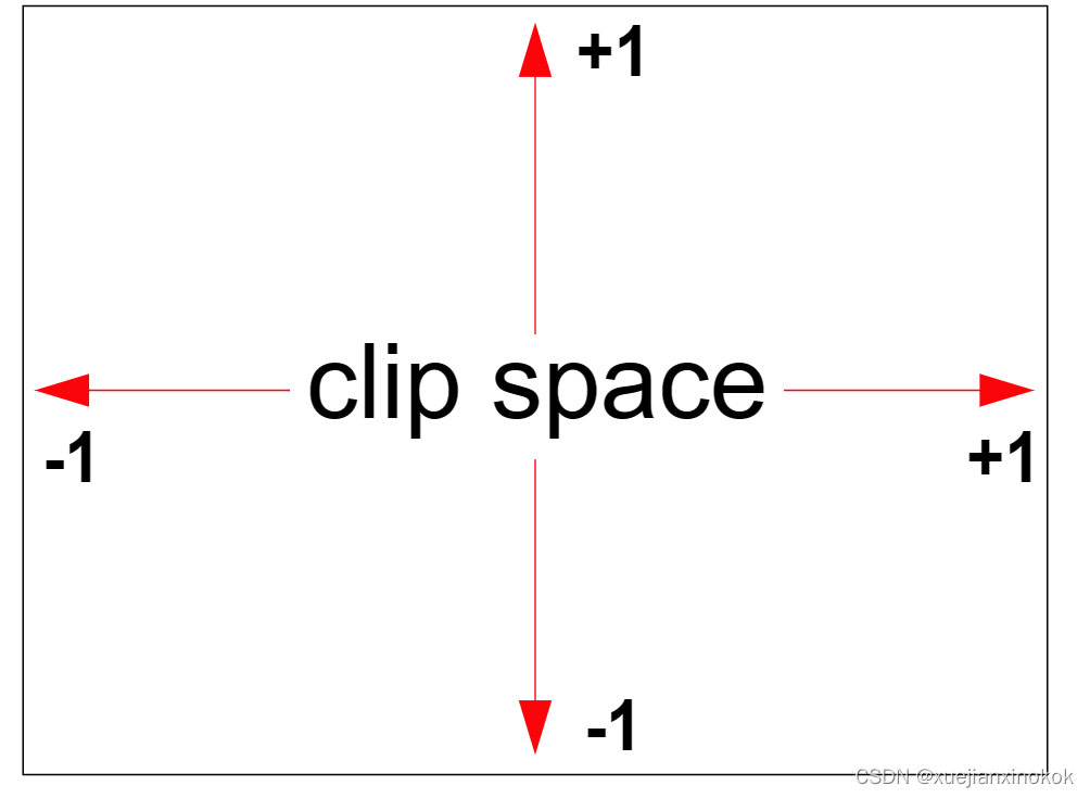
WebGPU 中的位置需要在裁剪空间(clip space)中返回,其中 X 从左侧的 -1.0 变为右侧的 +1.0,Y 从底部的 -1.0 变为顶部的 +1.0。无论我们绘制的纹理大小如何,都是如此。
vs 函数声明了一个包含 3 个 vec2f 的数组。每个 vec2f 由两个 32 位浮点值组成。然后代码用 3 个 vec2f 填充该数组。
        var pos = array<vec2f, 3>(
          vec2f( 0.0,  0.5),  // top center
          vec2f(-0.5, -0.5),  // bottom left
          vec2f( 0.5, -0.5)   // bottom right
        );
最后,它使用 vertexIndex 从数组中返回 3 个值之一。由于该函数需要 4 个浮点值作为其返回类型,并且由于 pos 是 vec2f 的数组,因此代码为其余的 2 个值提供了 0.0 和 1.0 。
return vec4f(pos[vertexIndex], 0.0, 1.0);
着色器模块还声明了一个名为 fs 的函数,该函数使用 @fragment 属性声明,使其成为片段着色器函数。
@fragment fn fs() -> @location(0) vec4f {
此函数不接受任何参数,并在 location(0) 处返回 vec4f 。这意味着它将写入第一个渲染目标。稍后我们会将第一个渲染目标作为我们的画布。
return vec4f(1, 0, 0, 1);
代码返回红色的 1, 0, 0, 1 。 WebGPU 中的颜色通常指定为从 0.0 到 1.0 的浮点值,其中上述 4 个值分别对应红色、绿色、蓝色和 alpha。
当 GPU 光栅化三角形(用像素绘制它)时,它会调用片段着色器来找出每个像素的颜色。在我们的例子中,我们只是返回红色。
需要注意的另一件事是 label 。您可以使用 WebGPU 创建的几乎每个对象都可以使用 label 。标签完全是可选的,但最好为您制作的所有东西贴上标签。原因是,当您遇到错误时,大多数 WebGPU 实现都会打印一条错误消息,其中包含与错误相关的事物的标签。
在一个普通的应用程序中,你会有 100 或 1000 的缓冲区、纹理、着色器模块、管道等…如果你得到一个像 “WGSL syntax error in shaderModule at line 10” 这样的错误,如果你有 100 个着色器模块,哪个有错误?如果你给模块贴上标签,那么你会得到一个更像 "WGSL syntax error in shaderModule(‘our hardcoded red triangle shaders’) at line 10 的错误,这是一种更有用的错误信息,可以为你节省大量时间来跟踪问题。
现在我们已经创建了一个着色器模块,接下来我们需要制作一个渲染管线
  const pipeline = device.createRenderPipeline({


    label: 'our hardcoded red triangle pipeline',
    layout: 'auto',
    vertex: {


      module,
      entryPoint: 'vs',
    },
    fragment: {


      module,
      entryPoint: 'fs',
      targets: [{

     format: presentationFormat }],
    },
  });
在这个例子里,没什么可看的。我们将 layout 设置为 ‘auto’ ,这意味着要求 WebGPU 从着色器中获取数据布局。不过我们没有使用任何数据。
然后,我们告诉渲染管线使用着色器模块中的 vs 函数作为顶点着色器,使用 fs 函数作为片段着色器。另外我们告诉它第一个渲染目标的格式。 “渲染目标”是指我们将渲染到的纹理。我们创建了一个管道,我们必须指定我们将使用该管道最终渲染到的纹理的格式。
targets 数组的元素 0 对应于我们为片段着色器的返回值指定的位置 0。稍后,我们将该目标设置为画布的纹理。
接下来我们准备一个 GPURenderPassDescriptor ,它描述了我们想要绘制哪些纹理以及如何使用它们。
  const renderPassDescriptor = {


    label: 'our basic canvas renderPass',
    colorAttachments: [
      {


        // view: <- to be filled out when we render
        clearValue: [0.3, 0.3, 0.3, 1],
        loadOp: 'clear',
        storeOp: 'store',
      },
    ],
  };
GPURenderPassDescriptor 有一个 colorAttachments 数组,其中列出了我们将渲染到的纹理以及如何处理这些纹理。我们将等待填充我们实际想要渲染的纹理。现在,我们设置了一个简单的半深灰色值,以及一个 loadOp 和 storeOp 。 loadOp: ‘clear’ 指定在绘制之前将纹理清除为清除值。另一个选项是 ‘load’ ,这意味着将纹理的现有内容加载到 GPU 中,这样我们就可以绘制已经存在的内容。 storeOp: ‘store’ 表示存储我们绘制的结果。我们也可以传递 ‘discard’ ,这会丢弃我们绘制的内容。我们将在另一篇文章中介绍为什么我们可能想要这样做。
现在是渲染的时候了。
  function render() {


    // Get the current texture from the canvas context and
    // set it as the texture to render to.
    renderPassDescriptor.colorAttachments[0].view =
        context.getCurrentTexture().createView();

    // make a command encoder to start encoding commands
    const encoder = device.createCommandEncoder({

     label: 'our encoder' });

    // make a render pass encoder to encode render specific commands
    const pass = encoder.beginRenderPass(renderPassDescriptor);
    pass.setPipeline(pipeline);
    pass.draw(3);  // call our vertex shader 3 times
    pass.end();

    const commandBuffer = encoder.finish();
    device.queue.submit([commandBuffer]);
  }

  render();
首先我们调用 context.getCurrentTexture() 来获取将出现在画布中的纹理。调用 createView 可以查看纹理的特定部分,但如果没有参数,它将返回默认部分,这正是我们在这种情况下想要的。在这种情况下,我们唯一的 colorAttachment 是来自画布的纹理视图,我们通过在开始时创建的上下文获得它。同样, colorAttachments 数组的元素 0 对应于我们为片段着色器的返回值指定的 location(0) 。
接下来我们创建一个命令编码器。命令编码器用于创建命令缓冲区。我们用它来编码命令,然后“提交”它创建的命令缓冲区来执行命令。
然后,我们使用命令编码器通过调用 beginRenderPass 创建渲染通道编码器。渲染通道编码器是用于创建与渲染相关的命令的特定编码器。我们将 renderPassDescriptor 传递给它以告诉它我们要渲染到哪个纹理。
我们对命令 setPipeline 进行编码,以设置我们的管道,然后通过使用 3 调用 draw 来告诉它执行我们的顶点着色器 3 次。默认情况下,每执行 3 次我们的顶点着色器,将通过连接绘制一个三角形刚刚从顶点着色器返回的 3 个值。
最后我们结束渲染通道,然后结束编码器。这为我们提供了一个命令缓冲区,表示我们刚刚指定的步骤。最后我们提交要执行的命令缓冲区。
当执行 draw 命令时,这将是我们的状态
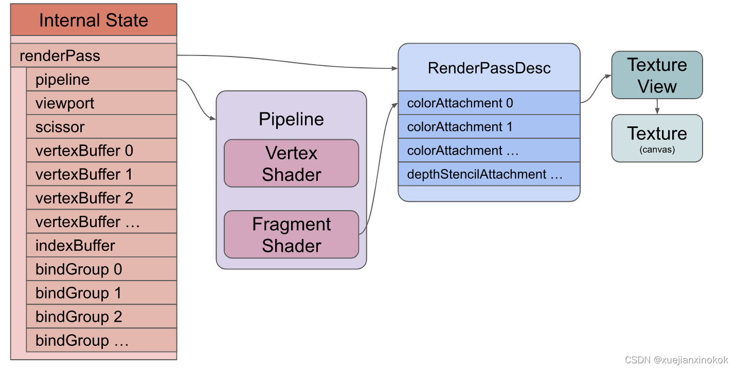
我们没有纹理、没有缓冲区、没有绑定组,但我们有一个管道、一个顶点和片段着色器,以及一个渲染过程描述符,它告诉我们的着色器渲染到画布纹理。
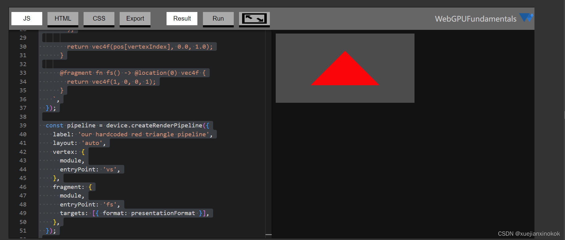
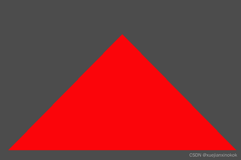
下边是全部代码和运行结果截图:
@import url(https://webgpufundamentals.org/webgpu/resources/webgpu-lesson.css);

<canvas></canvas>
<script type="module">

async function main() {


  const adapter = await navigator.gpu?.requestAdapter();
  const device = await adapter?.requestDevice();
  if (!device) {


    fail('need a browser that supports WebGPU');
    return;
  }

  // Get a WebGPU context from the canvas and configure it
  const canvas = document.querySelector('canvas');
  const context = canvas.getContext('webgpu');
  const presentationFormat = navigator.gpu.getPreferredCanvasFormat();
  context.configure({


    device,
    format: presentationFormat,
      });

  const module = device.createShaderModule({


    label: 'our hardcoded red triangle shaders',
    code: `
      @vertex fn vs(
        @builtin(vertex_index) vertexIndex : u32
      ) -> @builtin(position) vec4f {
        var pos = array<vec2f, 3>(
          vec2f( 0.0,  0.5),  // top center
          vec2f(-0.5, -0.5),  // bottom left
          vec2f( 0.5, -0.5)   // bottom right
        );

        return vec4f(pos[vertexIndex], 0.0, 1.0);
      }

      @fragment fn fs() -> @location(0) vec4f {
        return vec4f(1, 0, 0, 1);
      }
    `,
  });

  const pipeline = device.createRenderPipeline({


    label: 'our hardcoded red triangle pipeline',
    layout: 'auto',
    vertex: {


      module,
      entryPoint: 'vs',
    },
    fragment: {


      module,
      entryPoint: 'fs',
      targets: [{

       format: presentationFormat }],
    },
  });

  const renderPassDescriptor = {


    label: 'our basic canvas renderPass',
    colorAttachments: [
      {


        // view: <- to be filled out when we render
        clearValue: [0.3, 0.3, 0.3, 1],
        loadOp: 'clear',
        storeOp: 'store',
      },
    ],
  };

  function render() {


    // Get the current texture from the canvas context and
    // set it as the texture to render to.
    renderPassDescriptor.colorAttachments[0].view =
        context.getCurrentTexture().createView();

    // make a command encoder to start encoding commands
    const encoder = device.createCommandEncoder({

       label: 'our encoder' });

    // make a render pass encoder to encode render specific commands
    const pass = encoder.beginRenderPass(renderPassDescriptor);
    pass.setPipeline(pipeline);
    pass.draw(3);  // call our vertex shader 3 times.
    pass.end();

    const commandBuffer = encoder.finish();
    device.queue.submit([commandBuffer]);
  }

  render();
}

function fail(msg) {


  // eslint-disable-next-line no-alert
  alert(msg);
}

main();
</script>
重要的是要强调我们调用的所有这些函数,如 setPipeline 和 draw 仅将命令添加到命令缓冲区。他们实际上并不执行命令。当我们将命令缓冲区提交到设备队列时执行这些命令。
So, now we’ve seen a very small working WebGPU example. It should be pretty obvious that hard coding a triangle inside a shader is not very flexible. We need ways to provide data and we’ll cover those in the following articles. The points to take away from the code above,
所以,现在我们已经看到了一个非常小的 WebGPU 工作示例。很明显,在着色器中硬编码三角形不是很灵活。我们需要提供数据的方法,我们将在以下文章中介绍这些方法。从上面的代码中获得的要点如下:
- WebGPU 只是运行着色器。由你来给它们填充代码来做有用的事情
- 着色器在着色器模块中指定,然后装配到渲染管道
- WebGPU 可以绘制三角形
- WebGPU 绘制到纹理(我们碰巧从画布上获取纹理)
- WebGPU 通过编码命令然后提交它们来工作。
3. 在 GPU 上运行计算 Run computations on the GPU
让我们编写一个在 GPU 上进行一些计算的基本示例
我们从相同的代码开始获取 WebGPU 设备
async function main() {


  const adapter = await gpu?.requestAdapter();
  const device = await adapter?.requestDevice();
  if (!device) {


    fail('need a browser that supports WebGPU');
    return;
  }
当我们创建着色器模块时
  const module = device.createShaderModule({


    label: 'doubling compute module',
    code: `
      @group(0) @binding(0) var<storage, read_write> data: array<f32>;

      @compute @workgroup_size(1) fn computeSomething(
        @builtin(global_invocation_id) id: vec3<u32>
      ) {
        let i = id.x;
        data[i] = data[i] * 2.0;
      }
    `,
  });
首先,我们声明一个名为 data 的变量,类型为 storage ,我们希望它能够读取和写入。
@group(0) @binding(0) var<storage, read_write> data: array<f32>;
We declare its type as array which means an array of 32bit floating point values. We tell it we’re going to specify this array on binding location 0 (the binding(0)) in bindGroup 0 (the @group(0)).
我们将其类型声明为 array ,这意味着一个 32 位浮点值数组。我们告诉它我们将在绑定组 0( @group(0) )中的绑定位置 0( binding(0) )上指定这个数组。
然后我们用 @compute 属性声明一个名为 computeSomething 的函数,使其成为计算着色器。
      @compute @workgroup_size(1) fn computeSomething(
        @builtin(global_invocation_id) id: vec3u
      ) {


        ...
Compute shaders are required to declare a workgroup size which we will cover later. For now we’ll just set it to 1 with the attribute @workgroup_size(1). We declare it to have one parameter id which uses a vec3u. A vec3u is three unsigned 32 integer values. Like our vertex shader above, this is the iteration number. It’s different in that compute shader iteration numbers are 3 dimensional (have 3 values). We declare id to get its value from the built-in global_invocation_id.
计算着色器(Compute shaders)需要声明我们稍后将介绍的工作组大小。现在我们只是将用 属性 @workgroup_size(1)把它设置为 1 。我们声明它有一个使用 vec3u 的参数 id 。 vec3u 是三个无符号 32 位整数值。就像我们上面的顶点着色器一样,这是迭代次数。不同之处在于计算着色器迭代次数是 3 维的(有 3 个值)。我们声明 id 以从内置的 global_invocation_id 中获取它的值。
您可以认为计算着色器是这样运行的。这是一个简化说明,但现在就可以了。
// pseudo code
for (z = 0; z < depth; ++z) {


  for (y = 0; y < height; ++y) {


    for (x = 0; x < width; ++x) {


      const global_invocation_id = {

    x, y, z};
      computeShaderFn(global_invocation_id);
    }
  }
}
最后我们使用 id 的 x 属性对 data 进行索引,并将每个值乘以2
        let i = id.x;
        data[i] = data[i] * 2.0;
上面, i 只是 3 个迭代数字中的第一个。
现在我们已经创建了着色器,我们需要创建一个管道
  const pipeline = device.createComputePipeline({


    label: 'doubling compute pipeline',
    layout: 'auto',
    compute: {


      module,
      entryPoint: 'computeSomething',
    },
  });
Here we just tell it we’re using a compute stage from the shader module we created and we want to call the computeSomething function. layout is ‘auto’ again, telling WebGPU to figure out the layout from the shaders. [5]
在这里我们只是告诉它在 compute 阶段使用我们创建的着色器 module 中并且想要调用 computeSomething 函数。 layout 又是 ‘auto’ ,告诉 WebGPU 从着色器中找出布局。 [见注释5]
接下来我们需要一些数据
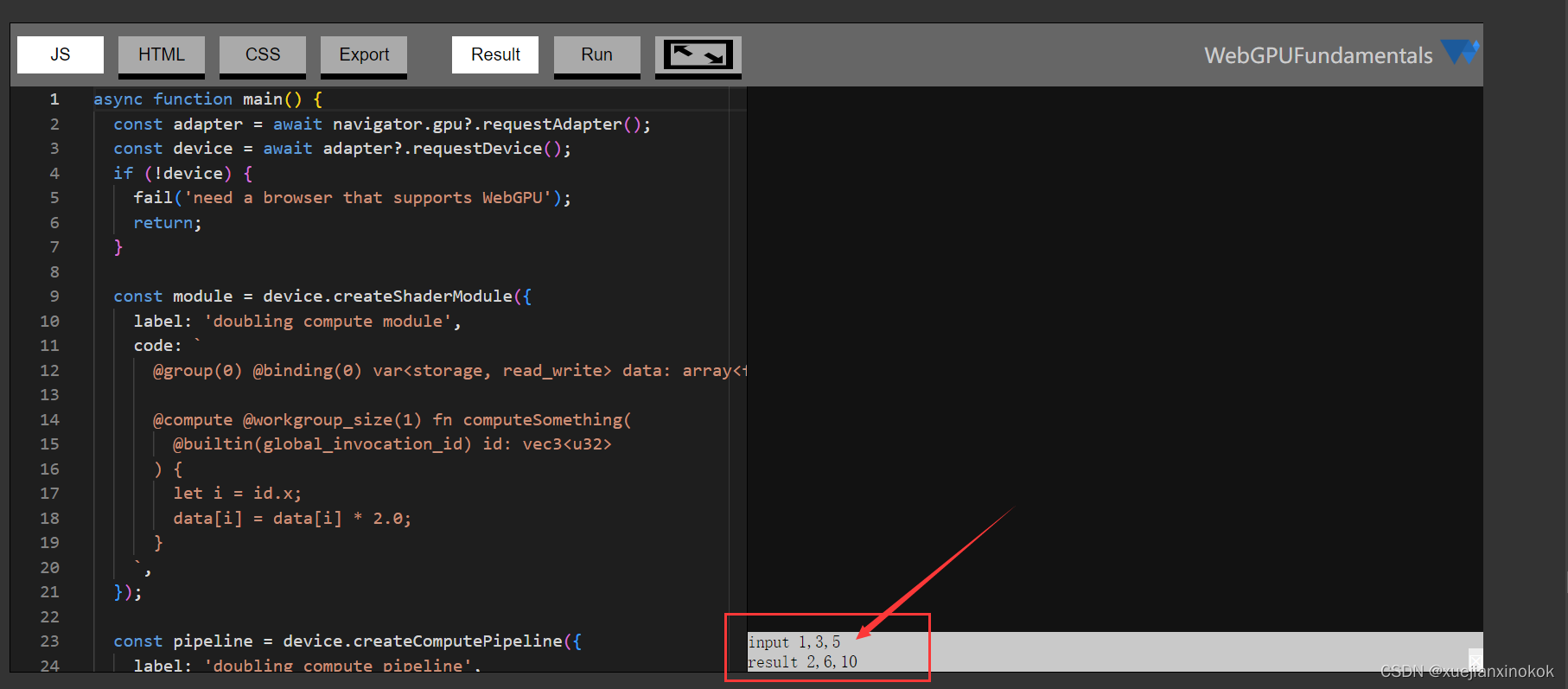
const input = new Float32Array([1, 3, 5]);
该数据仅存在于 JavaScript 中。为了让 WebGPU 使用它,需要创建一个存在于 GPU 上的缓冲区并将数据复制到缓冲区中。
  // create a buffer on the GPU to hold our computation
  // input and output
  const workBuffer = device.createBuffer({


    label: 'work buffer',
    size: input.byteLength,
    usage: GPUBufferUsage.STORAGE | GPUBufferUsage.COPY_SRC | GPUBufferUsage.COPY_DST,
  });
  // Copy our input data to that buffer
  device.queue.writeBuffer(workBuffer, 0, input);
上面我们调用 device.createBuffer 来创建缓冲区。 size 是以字节为单位的大小,在这种情况下它将是 12,因为 Float32Array 的 3 个值的字节大小是 12。如果您不熟悉 Float32Array 和类型化数组,请参阅本文 。
我们创建的每个 WebGPU 缓冲区都必须指定一个 usage 。我们可以传递一堆标志以供使用,但并非所有标志都可以一起使用。这里我们说我们希望通过传递 GPUBufferUsage.STORAGE 将此缓冲区用作 storage 。这使得它与着色器中的 var<storage,…> 兼容。此外,我们希望能够将数据复制到此缓冲区,因此我们包含 GPUBufferUsage.COPY_DST 标志。最后,我们希望能够从缓冲区复制数据,因此我们包含了 GPUBufferUsage.COPY_SRC 。
Note that you can not directly read the contents of a WebGPU buffer from JavaScript. Instead you have to “map” it which is another way of requesting access to the buffer from WebGPU because the buffer might be in use and because it might only exist on the GPU.
请注意,不能直接从 JavaScript 读取 WebGPU 缓冲区的内容。相反,您必须“映射”它,这是从 WebGPU 请求访问缓冲区的另一种方式,因为缓冲区可能正在使用并且因为它可能只存在于 GPU 上。
WebGPU buffers that can be mapped in JavaScript can’t be used for much else. In other words, we can not map the buffer we just created above and if we try to add the flag to make it mappable we’ll get an error that that is not compatible with usage STORAGE.
可以在 JavaScript 中映射的 WebGPU 缓冲区不能用于其他用途。换句话说,我们无法映射我们刚刚在上面创建的缓冲区,如果我们尝试添加标志以使其可映射,我们将收到一个与 STORAGE 用法不兼容的错误。
So, in order to see the result of our computation, we’ll need another buffer. After running the computation, we’ll copy the buffer above to this result buffer and set its flags so we can map it.
因此,为了查看我们的计算结果,我们需要另一个缓冲区。运行计算后,我们将把上面的缓冲区复制到这个结果缓冲区并设置它的标志以便我们可以映射它。
  // create a buffer on the GPU to get a copy of the results
  const resultBuffer = device.createBuffer({


    label: 'result buffer',
    size: input.byteLength,
    usage: GPUBufferUsage.MAP_READ | GPUBufferUsage.COPY_DST
  });
MAP_READ 表示我们希望能够映射此缓冲区以读取数据。
为了告诉我们的着色器我们希望它工作的缓冲区,我们需要创建一个 bindGroup
  // Setup a bindGroup to tell the shader which
  // buffer to use for the computation
  const bindGroup = device.createBindGroup({


    label: 'bindGroup for work buffer',
    layout: pipeline.getBindGroupLayout(0),
    entries: [
      {

     binding: 0, resource: {

     buffer: workBuffer } },
    ],
  });
We get the layout for the bindGroup from the pipeline. Then we setup bindGroup entries. The 0 in pipeline.getBindGroupLayout(0) corresponds to the @group(0) in the shader. The {binding: 0 … of the entries corresponds to the @group(0) @binding(0) in the shader.
我们从管道中获取 bindGroup 的布局。然后我们设置 bindGroup 条目。 pipeline.getBindGroupLayout(0) 中的 0 对应着色器中的 @group(0) 。 entries 的 {binding: 0 … 对应shader中的 @group(0) @binding(0) 。
现在我们可以开始编码命令了
  // Encode commands to do the computation
  const encoder = device.createCommandEncoder({


    label: 'doubling encoder',
  });
  const pass = encoder.beginComputePass({


    label: 'doubling compute pass',
  });
  pass.setPipeline(pipeline);
  pass.setBindGroup(0, bindGroup);
  pass.dispatchWorkgroups(input.length);
  pass.end();
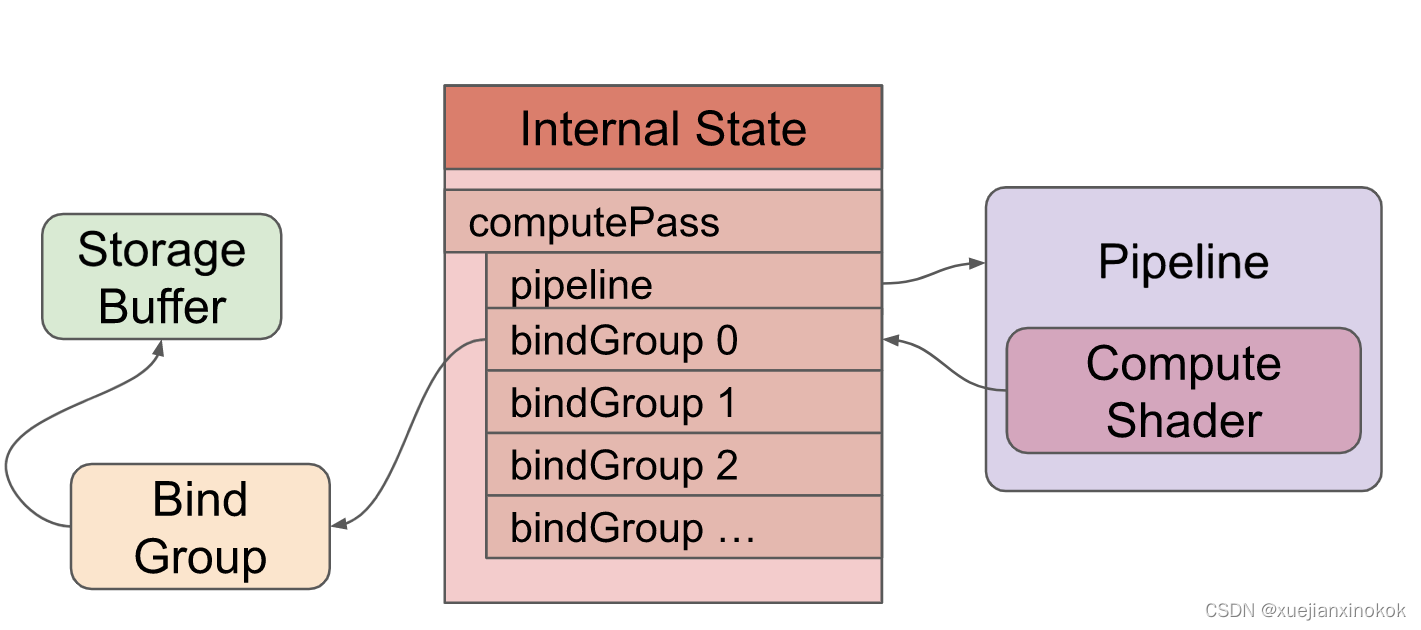
We create a command encoder. We start a compute pass. We set the pipeline, then we set the bindGroup. Here, the 0 in pass.setBindGroup(0, bindGroup) corresponds to @group(0) in the shader. We then call dispatchWorkgroups and in this case we pass it input.length which is 3 telling WebGPU to run the compute shader 3 times. We then end the pass.
我们创建一个命令编码器。并开始一个计算过程。先设置管道,然后设置 bindGroup。这里, pass.setBindGroup(0, bindGroup) 中的 0 对应shader中的 @group(0) 。然后我们调用 dispatchWorkgroups ,在这种情况下,我们将它传递给 input.length ,即 3 告诉 WebGPU 运行计算着色器 3 次。然后我们结束pass。
下面是执行 dispatchWorkgroups 时的情况
计算完成后,我们要求 WebGPU 从 buffer 复制到 resultBuffer
  // Encode a command to copy the results to a mappable buffer.
  encoder.copyBufferToBuffer(workBuffer, 0, resultBuffer, 0, resultBuffer.size);
现在我们可以 finish 编码器获取命令缓冲区,然后提交该命令缓冲区。
  // Finish encoding and submit the commands
  const commandBuffer = encoder.finish();
  device.queue.submit([commandBuffer]);
We then map the results buffer and get a copy of the data
然后我们映射结果缓冲区并获得数据的副本
  // Read the results
  await resultBuffer.mapAsync(GPUMapMode.READ);
  const result = new Float32Array(resultBuffer.getMappedRange());

  console.log('input', input);
  console.log('result', result);

  resultBuffer.unmap();
To map the results buffer we call mapAsync and have to await for it to finish. Once mapped, we can call resultBuffer.getMappedRange() which with no parameters will return an ArrayBuffer of entire buffer. We put that in a Float32Array typed array view and then we can look at the values. One important detail, the ArrayBuffer returned by getMappedRange is only valid until we called unmap. After unmap its length with be set to 0 and its data no longer accessible.
要映射结果缓冲区,我们调用 mapAsync 并且必须调用 await 才能完成。映射后,我们可以调用不带参数的 resultBuffer.getMappedRange() ,它将返回整个缓冲区的 ArrayBuffer 。我们把它放在一个 Float32Array 类型的数组视图中,然后我们可以查看值。一个重要的细节是, getMappedRange 返回的 ArrayBuffer 仅在我们调用 unmap 之前有效。在 unmap 之后,它的长度被设置为 0,并且它的数据不再可访问。
运行我们可以看到我们得到了结果,所有的数字都翻了一番。
我们将在其他文章中介绍如何真正使用计算着色器。现在,您希望已经对 WebGPU 的功能有了一些了解。其他一切由您决定!将 WebGPU 视为类似于其他编程语言。它提供了一些基本功能,剩下的就留给您发挥创意了。
让 WebGPU 编程与众不同的是这些函数、顶点着色器、片段着色器和计算着色器,它们在您的 GPU 上运行。一个 GPU 可以有超过 10000 个处理器,这意味着它们可以并行执行超过 10000 个计算,这可能比你的 CPU 可以并行执行的计算高出 3 个或更多数量级。
4. 简单的画布调整大小 Simple Canvas Resizing
在我们继续之前,让我们回到我们的三角形绘图示例并添加一些对调整画布大小的基本支持。调整画布大小实际上是一个可能有很多微妙之处的主题,因此有一整篇文章都在讨论它。现在我们只添加一些基本支持
首先我们添加一些 CSS 让我们的画布填满页面
<style>
html, body {


  margin: 0;       /* remove the default margin          */
  height: 100%;    /* make the html,body fill the page   */
}
canvas {


  display: block;  /* make the canvas act like a block   */
  width: 100%;     /* make the canvas fill its container */
  height: 100%;
}
</style>
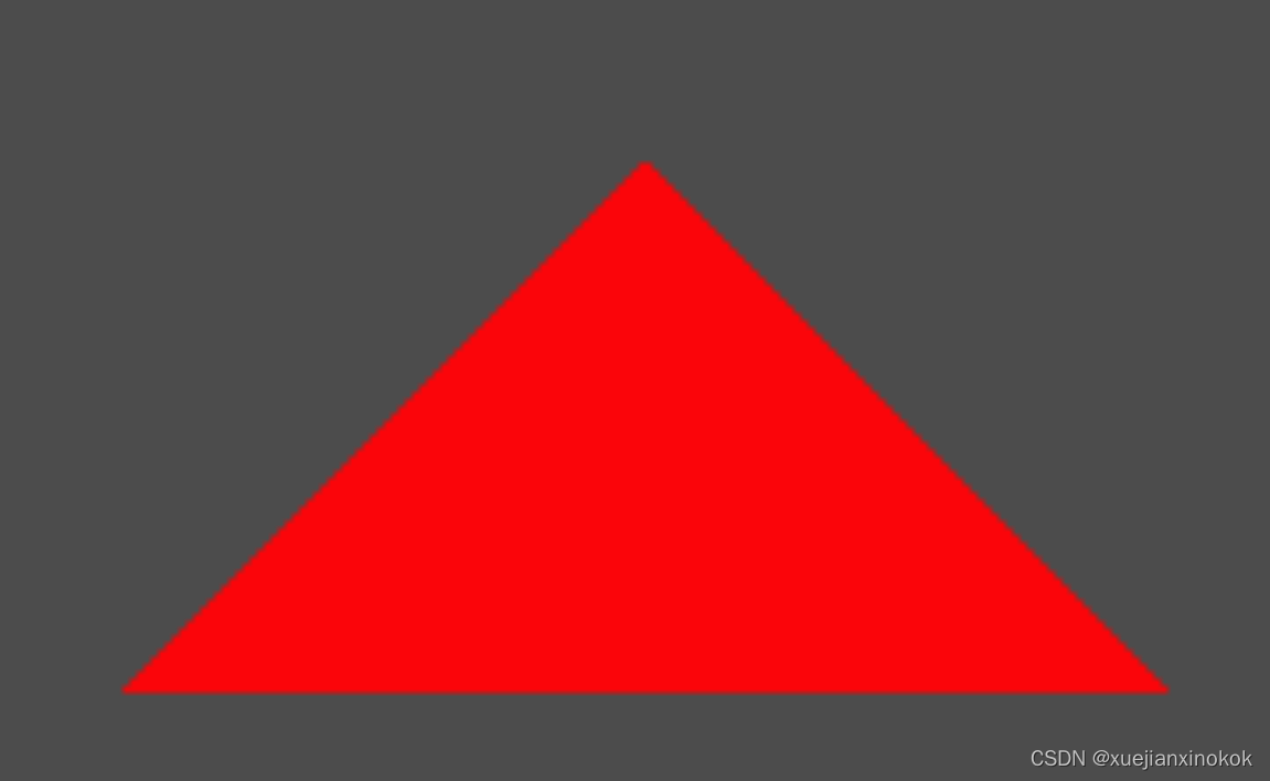
上边 CSS 只是将使画布显示以覆盖页面,但它不会改变画布本身的分辨率,因此您可能会注意到如果您将下面的示例变大,就像您单击全屏按钮一样,您会看到三角形的边缘是块状的。
默认情况下, 标签的分辨率为 300x150 像素。我们想调整画布以匹配大小。一个好的方法是使用 ResizeObserver 。您创建一个 ResizeObserver 并为其提供一个函数,以便在您要求它观察的元素改变其大小时调用。然后告诉它要观察哪些元素。
    ...
    // render();// 这行被删除

    const observer = new ResizeObserver(entries => {


      for (const entry of entries) {


        const canvas = entry.target;
        const width = entry.contentBoxSize[0].inlineSize;
        const height = entry.contentBoxSize[0].blockSize;
        canvas.width = Math.min(width, device.limits.maxTextureDimension2D);
        canvas.height = Math.min(height, device.limits.maxTextureDimension2D);
        // re-render
        render();
      }
    });
    observer.observe(canvas);
在上面的代码中,我们遍历了所有条目,但应该只有一个,因为我们只观察我们的画布。我们需要将画布的大小限制为我们的设备支持的最大尺寸,否则 WebGPU 将开始生成我们试图制作太大的纹理的错误。
我们调用 render 以新的分辨率重新渲染三角形。我们删除了对 render 的旧调用,因为它不需要。当元素开始被观察时, ResizeObserver 将始终至少调用一次回调以报告元素的大小。
当我们在 render 中调用 context.getCurrentTexture() 时会创建新大小的纹理,因此无需执行任何操作。
在接下来的文章中,我们将介绍将数据传递到着色器的各种方法。
然后我们将介绍 WGSL 的基础知识。
我有点担心这些文章一开始会很无聊。如果你愿意,可以随意跳来跳去。请记住,如果您不理解您可能需要阅读或复习这些基础知识的内容。一旦我们掌握了基础知识,我们就会开始复习实际技术。
另一件事。所有示例程序都可以在网页中实时编辑。此外,它们都可以轻松导出到 jsfiddle 和 codepen 甚至 stackoverflow 。只需单击“导出”。
上面的代码以非常简洁的方式获取了一个 WebGPU 设备。更详细的方法是
async function start() {


  if (!navigator.gpu) {


    fail('this browser does not support WebGPU');
    return;
  }

  const adapter = await navigator.gpu.requestAdapter();
  if (!adapter) {


    fail('this browser supports webgpu but it appears disabled');
    return;
  }

  const device = await adapter?.requestDevice();
  device.lost.then((info) => {


    console.error(`WebGPU device was lost: ${

      info.message}`);

    // 'reason' will be 'destroyed' if we intentionally destroy the device.
    if (info.reason !== 'destroyed') {


      // try again
      start();
    }
  });

  main(device);
}
start();

function main(device) {


  ... do webgpu ...
}
device.lost 是一个开始时unresolved的promise 。它将解决设备是否以及何时丢失。设备丢失的原因有很多。也许用户运行了一个非常密集的应用程序并且它使他们的 GPU 崩溃了。也许用户更新了他们的驱动程序。也许用户有一个外部 GPU 并拔掉了它。也许另一个页面使用了大量 GPU,您的选项卡在后台,浏览器决定通过丢失后台选项卡设备来释放一些内存。关键是对于任何严肃的应用程序,您可能想要处理丢失设备的问题。
请注意, requestDevice 总是返回一个设备。它可能会开始丢失。 WebGPU 的设计使得在大多数情况下,设备看起来可以工作,至少从 API 级别来看是这样。创建事物并使用它们的调用似乎会成功,但它们实际上不会起作用。当 lost 承诺解决时,由您决定改怎么做。
5. 注释
[注释1] 实际上有5种模式。
‘point-list’ : 对于每个位置,画一个点
‘line-list’ : 每2个位置,画一条线
‘line-strip’ : 绘制连接最新点和先前点的线
‘triangle-list’ : 每3个位置,画一个三角形(默认)
‘triangle-strip’ :对于每个新位置,从它和最后两个位置绘制一个三角形
↩︎
[注释2]
片段着色器间接地将数据写入纹理。该数据不一定是颜色。例如,输出像素代表的表面方向是很常见的。 ↩︎
[注释3]
纹理也可以是像素的 3d 矩形、立方体贴图(形成立方体的 6 个像素正方形)和其他一些东西,但最常见的纹理是像素的 2d 矩形。 ↩︎
[注释4]
我们还可以在索引缓冲区中使用特定的 vertex_index 。这在关于顶点缓冲区的文章中有所介绍。 ↩︎
[注释5] ↩︎
layout: ‘auto’ 很方便,但是使用 layout: ‘auto’ 无法跨管道共享绑定组。此站点上的大多数示例从不使用具有多个管道的绑定组。我们将在另一篇文章中介绍显式布局。