目录
防火墙安全策略
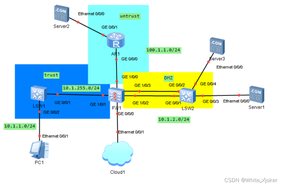
实验图
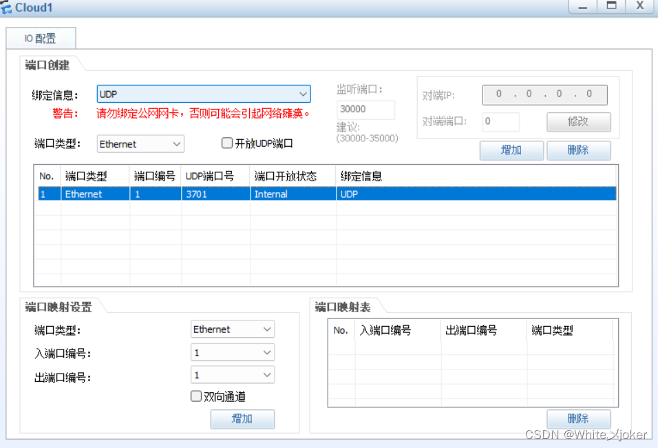
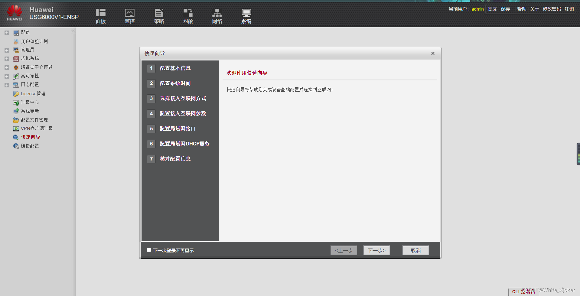
1.配置防火墙图形界面
先添加UDP端口
添加网段网卡
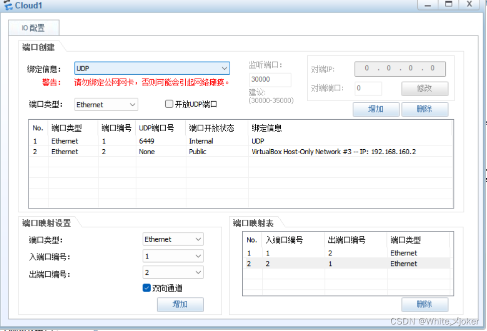
注意:
网段网卡Windows上,所以Windows可以通过这个网段网卡访问到防火墙上
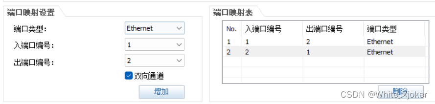
做端口映射,点击双向通道,点击添加
注意:
一般情况下防火墙在刚买下会有一个端口为管理口,自带IP地址,华为设备中,防火墙默认只有GigabitEthernet0/0/0端口是受信任端口,且ip地址为192.168.0.1
启动防火墙FW1

启动成功后,会提示输入Username以及Password
华为默认用户名以及密码为:
Username:admin
Password:Admin@123
登录成功后提示修改密码

The password needs to be changed. Change now? [Y/N]: y
Please enter old password:
Please enter new password:
Please confirm new password:

 Info: Your password has been changed. Save the change to survive a reboot.
*************************************************************************
*         Copyright (C) 2014-2018 Huawei Technologies Co., Ltd.         *
*                           All rights reserved.                        *
*               Without the owner's prior written consent,              *
*        no decompiling or reverse-engineering shall be allowed.        *
*************************************************************************


<USG6000V1>
Mar 17 2023 08:22:41 USG6000V1 SNMPADAPT/4/UPDATE_SUCCESS:OID 1.3.6.1.4.1.2011.6
.122.76.2.1 Succeed in updating database. (Module= "LOCATION-SDB", Pre-UpdateVer
sion= "0", UpdateVersion= "2018061815")
<USG6000V1>
查找防火墙 0/0/0 端口默认的IP地址
<USG6000V1>system-view
Enter system view, return user view with Ctrl+Z.
[USG6000V1]int g 0/0/0
[USG6000V1-GigabitEthernet0/0/0]display this
2023-03-17 08:25:48.180
#
interface GigabitEthernet0/0/0
 undo shutdown
 ip binding vpn-instance default ---- VPN的设置,单独隔离出来的一个口
 ip address 192.168.0.1 255.255.255.0
 alias GE0/METH
#
return
[USG6000V1-GigabitEthernet0/0/0]
将地址与回环端口的地址改为同一网段
[USG6000V1-GigabitEthernet0/0/0]ip address 192.168.160.1 24
[USG6000V1-GigabitEthernet0/0/0]
Mar 17 2023 08:45:36 USG6000V1 %%01FRAG/4/FRAG_PKT_EXCEED_THRESHOLD(l)[13]:The t
otal number of cached packet fragments on SPU 11 CPU 0 is 64, exceeding threshol
d value 64.
放行策略,RTPS协议
[USG6000V1-GigabitEthernet0/0/0]service-manage all permit
测试
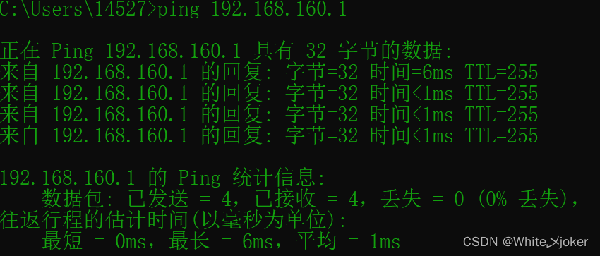
输入图形化界面的访问地址
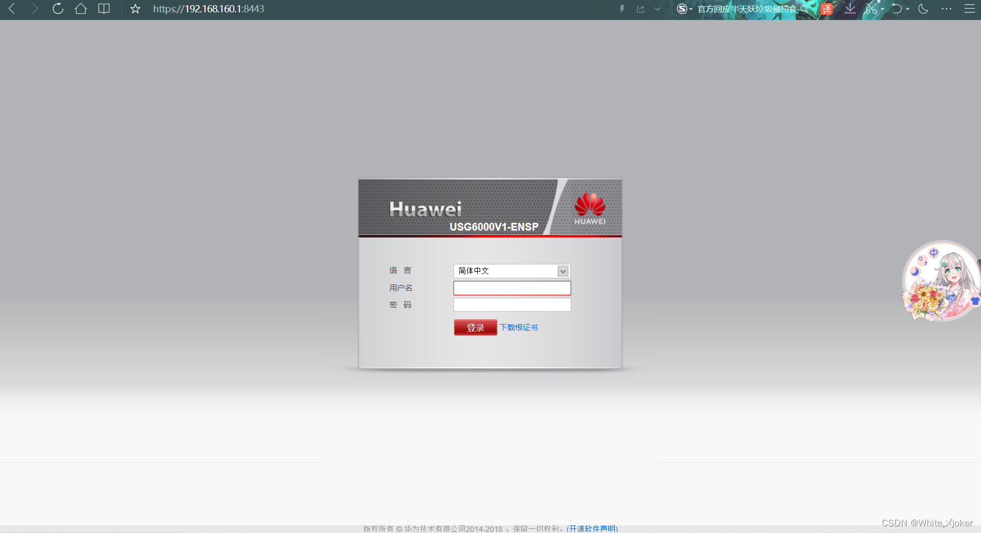
登陆刚才设置的用户名以及密码
2.配置untrust区域
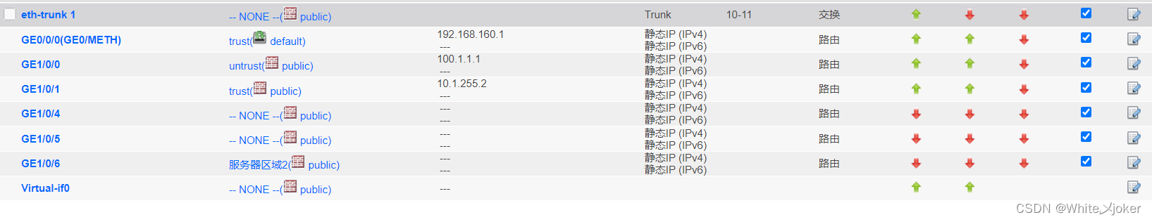
点击网络,进入接口
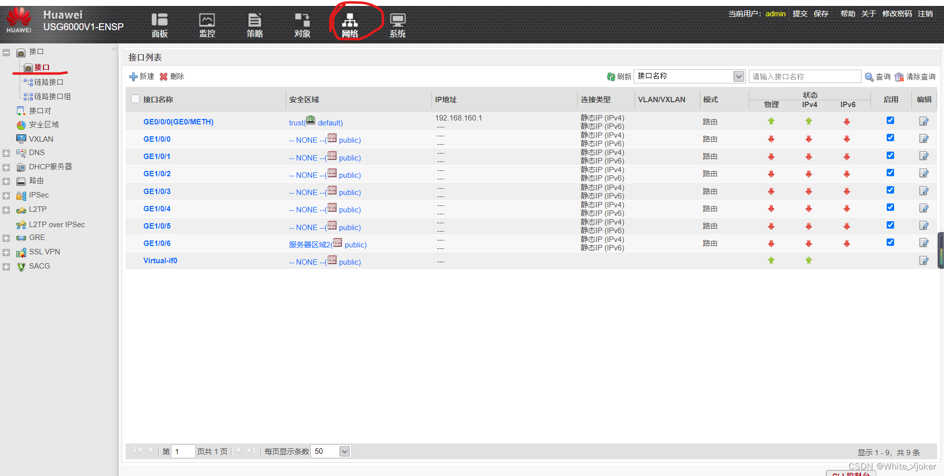
配置GE1/0/0接口
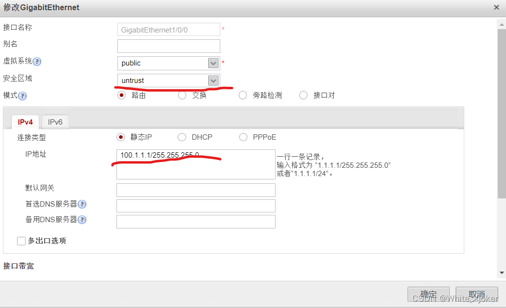
注意:
写上网关会出现默认路由,一般情况不写,自己进行配置
R1配置
<Huawei>sys
<Huawei>system-view
Enter system view, return user view with Ctrl+Z.
[ISp]sysname ISP
[ISP]int g 0/0/0
[ISP-GigabitEthernet0/0/0]ip address 100.1.1.2 24
Mar 17 2023 18:04:30-08:00 ISP %%01IFNET/4/LINK_STATE(l)[0]:The line protocol IP
 on the interface GigabitEthernet0/0/0 has entered the UP state.
[ISP-GigabitEthernet0/0/0]q
[ISP]int g 0/0/1
[ISP-GigabitEthernet0/0/1]ip address 200.1.1.1 24
Mar 17 2023 18:04:56-08:00 ISP %%01IFNET/4/LINK_STATE(l)[1]:The line protocol IP
 on the interface GigabitEthernet0/0/1 has entered the UP state.
[ISP-GigabitEthernet0/0/1]
R1中server2的配置
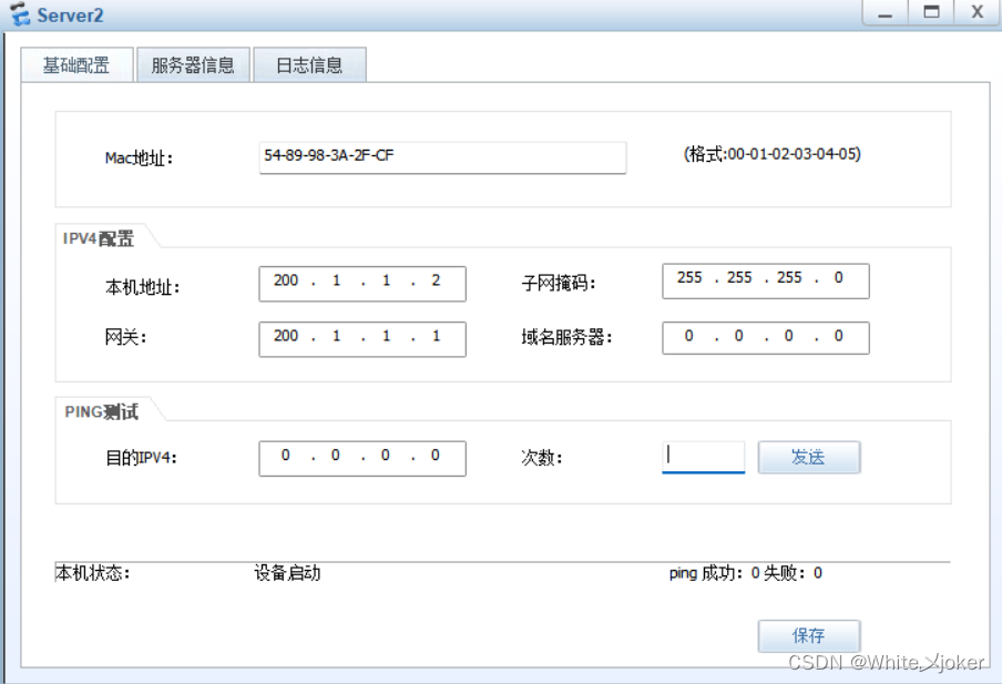
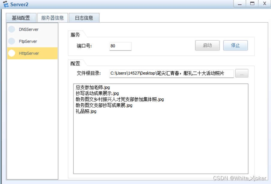
开启http服务
测试 --- ping 100.1.1.1 防火墙
[ISP]ping 100.1.1.1
  PING 100.1.1.1: 56  data bytes, press CTRL_C to break
    Request time out
    Request time out
    Request time out
    Request time out
    Request time out

  --- 100.1.1.1 ping statistics ---
    5 packet(s) transmitted
    0 packet(s) received
    100.00% packet loss

[ISP]
无法ping通:
原因 --- 默认是不允许(不放行)
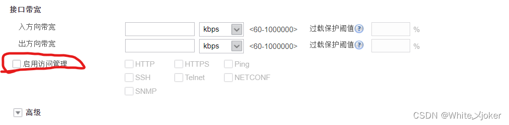
如何测试:
配置GE0/0/1口
[ISP]ping 100.1.1.1
  PING 100.1.1.1: 56  data bytes, press CTRL_C to break
    Reply from 100.1.1.1: bytes=56 Sequence=1 ttl=255 time=20 ms
    Reply from 100.1.1.1: bytes=56 Sequence=2 ttl=255 time=10 ms
    Reply from 100.1.1.1: bytes=56 Sequence=3 ttl=255 time=10 ms
    Reply from 100.1.1.1: bytes=56 Sequence=4 ttl=255 time=10 ms
    Reply from 100.1.1.1: bytes=56 Sequence=5 ttl=255 time=10 ms

  --- 100.1.1.1 ping statistics ---
    5 packet(s) transmitted
    5 packet(s) received
    0.00% packet loss
    round-trip min/avg/max = 10/12/20 ms

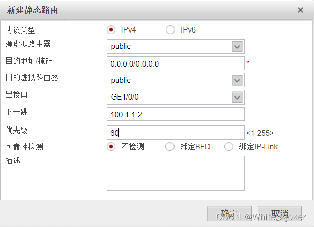
配置路由缺省
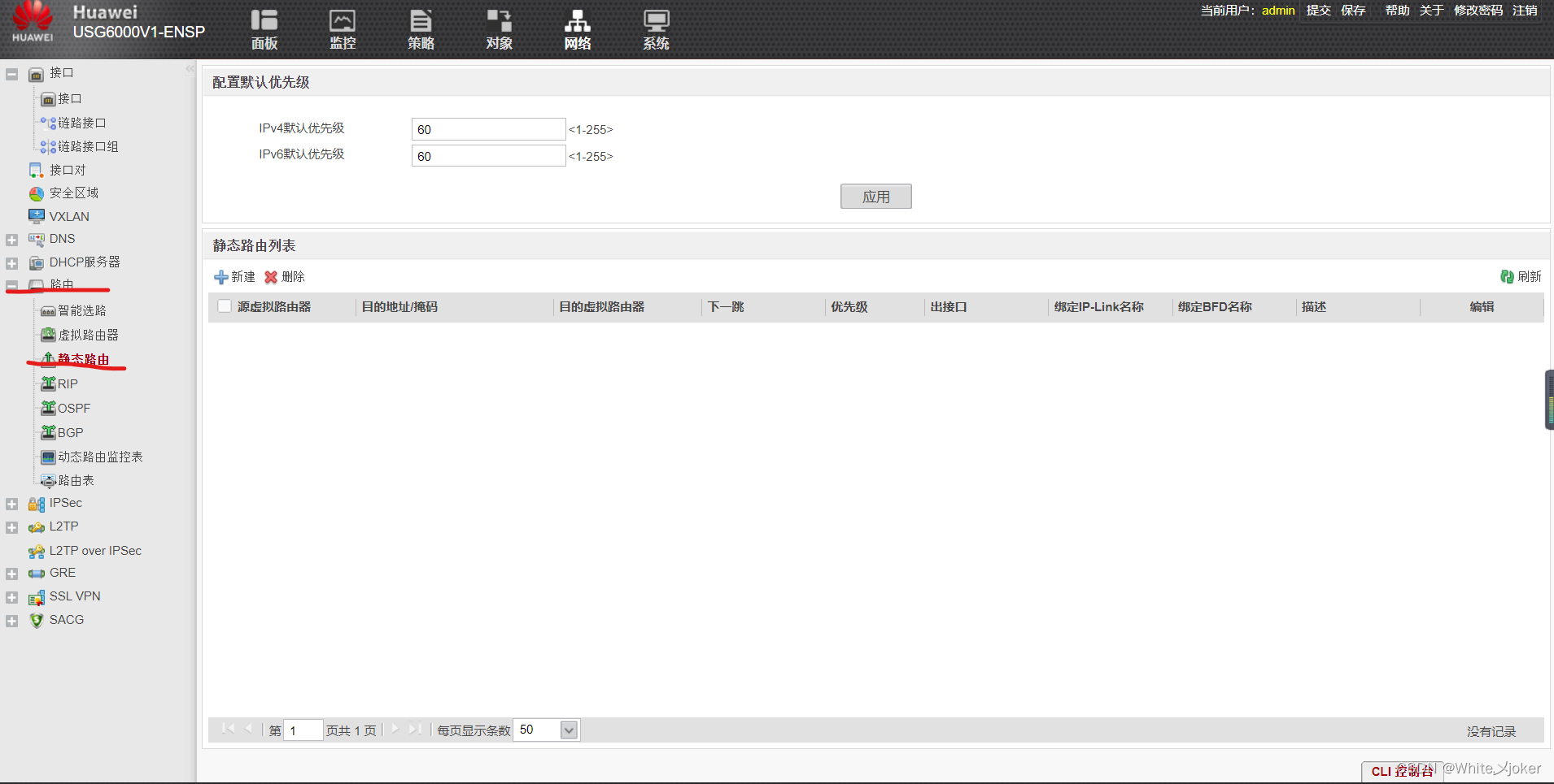
新建
2.配置trust区域
配置GE1/0/1接口
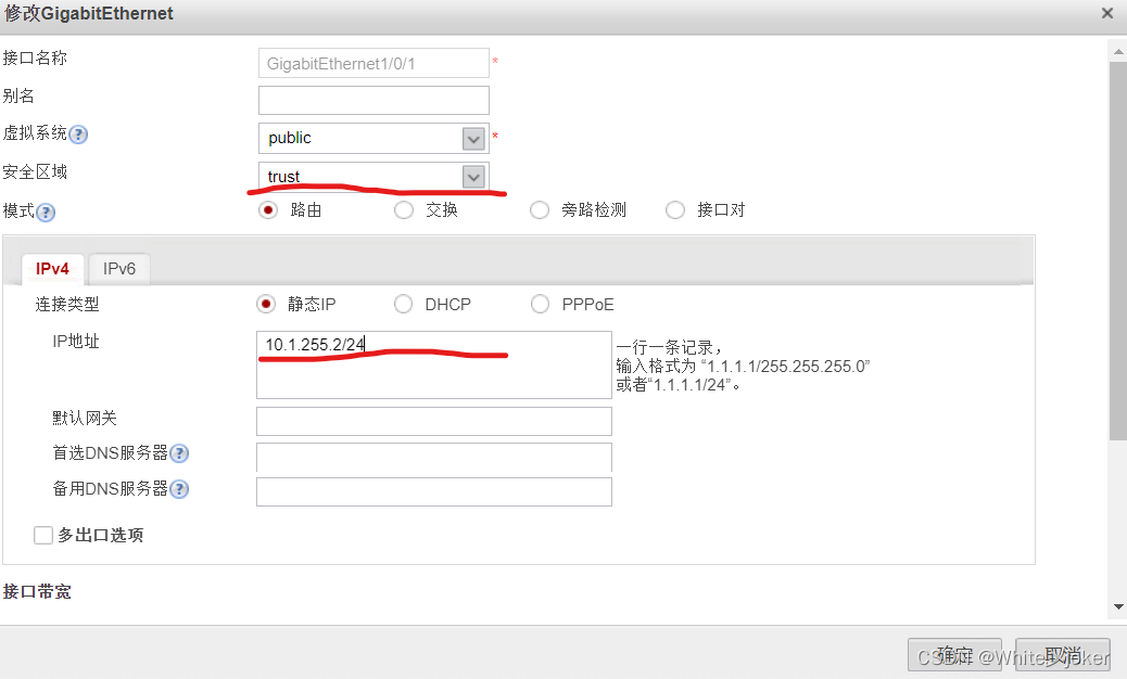
LSW1配置
<Huawei>system-view
Enter system view, return user view with Ctrl+Z.
[Huawei]sysname LSW1
[LSW1]
Mar 17 2023 18:23:07-08:00 LSW1 DS/4/DATASYNC_CFGCHANGE:OID 1.3.6.1.4.1.2011.5.2
5.191.3.1 configurations have been changed. The current change number is 4, the
change loop count is 0, and the maximum number of records is 4095.
[LSW1]vlan 2
[LSW1-vlan2]
Mar 17 2023 18:24:47-08:00 LSW1 DS/4/DATASYNC_CFGCHANGE:OID 1.3.6.1.4.1.2011.5.2
5.191.3.1 configurations have been changed. The current change number is 5, the
change loop count is 0, and the maximum number of records is 4095.
[LSW1-GigabitEthernet0/0/1]port default vlan 2
[LSW1-GigabitEthernet0/0/1]
Mar 17 2023 18:40:31-08:00 LSW1 %%01IFNET/4/IF_STATE(l)[2]:Interface Vlanif1 has
 turned into DOWN state.
Mar 17 2023 18:40:31-08:00 LSW1 %%01IFNET/4/IF_STATE(l)[3]:Interface Vlanif2 has
 turned into UP state.
Mar 17 2023 18:40:31-08:00 LSW1 %%01IFNET/4/LINK_STATE(l)[4]:The line protocol I
P on the interface Vlanif2 has entered the UP state.
[LSW1-vlan2]q
[LSW1]int g 0/0/1
[LSW1-GigabitEthernet0/0/1]port link-type access
Mar 17 2023 18:25:47-08:00 LSW1 DS/4/DATASYNC_CFGCHANGE:OID 1.3.6.1.4.1.2011.5.2
5.191.3.1 configurations have been changed. The current change number is 6, the
change loop count is 0, and the maximum number of records is 4095.
[LSW1-GigabitEthernet0/0/1]q
[LSW1]int Vlanif 2
[LSW1-Vlanif2]ip address 10.1.255.1 24
[LSW1-Vlanif2]q
Mar 17 2023 18:26:57-08:00 LSW1 DS/4/DATASYNC_CFGCHANGE:OID 1.3.6.1.4.1.2011.5.2
5.191.3.1 configurations have been changed. The current change number is 7, the
change loop count is 0, and the maximum number of records is 4095.
在LSW1上配置PC1的网关
[LSW1]vlan 3
[LSW1-vlan3]q
Mar 17 2023 18:27:57-08:00 LSW1 DS/4/DATASYNC_CFGCHANGE:OID 1.3.6.1.4.1.2011.5.2
5.191.3.1 configurations have been changed. The current change number is 8, the
change loop count is 0, and the maximum number of records is 4095.la
[LSW1]int Vlanif 3
[LSW1-Vlanif3]ip address 10.1.3.1 24
[LSW1-Vlanif3]q
Mar 17 2023 18:28:17-08:00 LSW1 DS/4/DATASYNC_CFGCHANGE:OID 1.3.6.1.4.1.2011.5.2
5.191.3.1 configurations have been changed. The current change number is 9, the
change loop count is 0, and the maximum number of records is 4095
[LSW1]int g 0/0/2
[LSW1-GigabitEthernet0/0/2]port link-type access
[LSW1-GigabitEthernet0/0/2]por
[LSW1-GigabitEthernet0/0/2]port
Mar 17 2023 18:28:47-08:00 LSW1 DS/4/DATASYNC_CFGCHANGE:OID 1.3.6.1.4.1.2011.5.2
5.191.3.1 configurations have been changed. The current change number is 10, the
 change loop count is 0, and the maximum number of records is 4095. def
[LSW1-GigabitEthernet0/0/2]port default vla
[LSW1-GigabitEthernet0/0/2]port default vlan 3
[LSW1-GigabitEthernet0/0/2]
Mar 17 2023 18:28:54-08:00 LSW1 %%01IFNET/4/IF_STATE(l)[0]:Interface Vlanif3 has
 turned into UP state.
Mar 17 2023 18:28:54-08:00 LSW1 %%01IFNET/4/LINK_STATE(l)[1]:The line protocol I
P on the interface Vlanif3 has entered the UP state.
Mar 17 2023 18:28:57-08:00 LSW1 DS/4/DATASYNC_CFGCHANGE:OID 1.3.6.1.4.1.2011.5.2
5.191.3.1 configurations have been changed. The current change number is 11, the
 change loop count is 0, and the maximum number of records is 4095.
[LSW1-GigabitEthernet0/0/2]
PC1配置
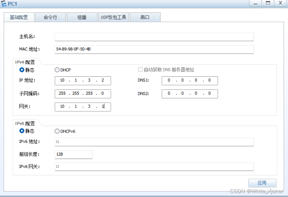
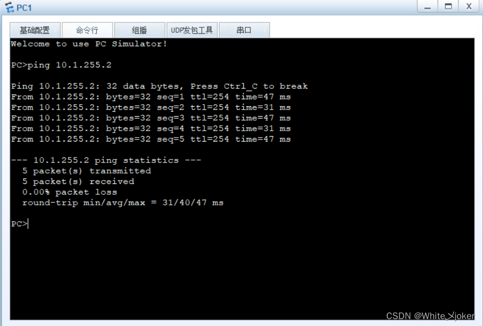
测试
打开ping
[LSW1]ping 10.1.255.2
  PING 10.1.255.2: 56  data bytes, press CTRL_C to break
    Reply from 10.1.255.2: bytes=56 Sequence=1 ttl=255 time=50 ms
    Reply from 10.1.255.2: bytes=56 Sequence=2 ttl=255 time=40 ms
    Reply from 10.1.255.2: bytes=56 Sequence=3 ttl=255 time=50 ms
    Reply from 10.1.255.2: bytes=56 Sequence=4 ttl=255 time=50 ms
    Reply from 10.1.255.2: bytes=56 Sequence=5 ttl=255 time=40 ms

  --- 10.1.255.2 ping statistics ---
    5 packet(s) transmitted
    5 packet(s) received
    0.00% packet loss
    round-trip min/avg/max = 40/46/50 ms

[LSW1]
配置回包路由
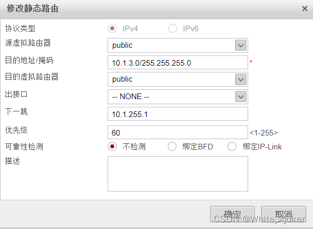
测试
3.配置DMZ区域
配置GE1/0/2接口
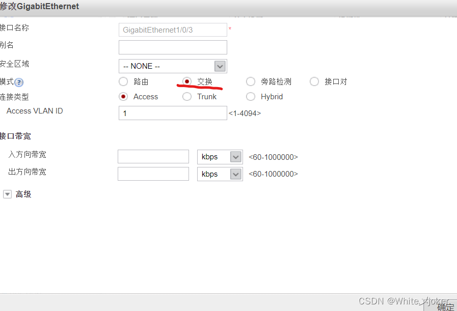
注意:
GE1/0/3接口配置与GE1/0/2相同
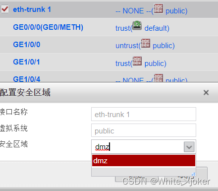
接口聚合配置
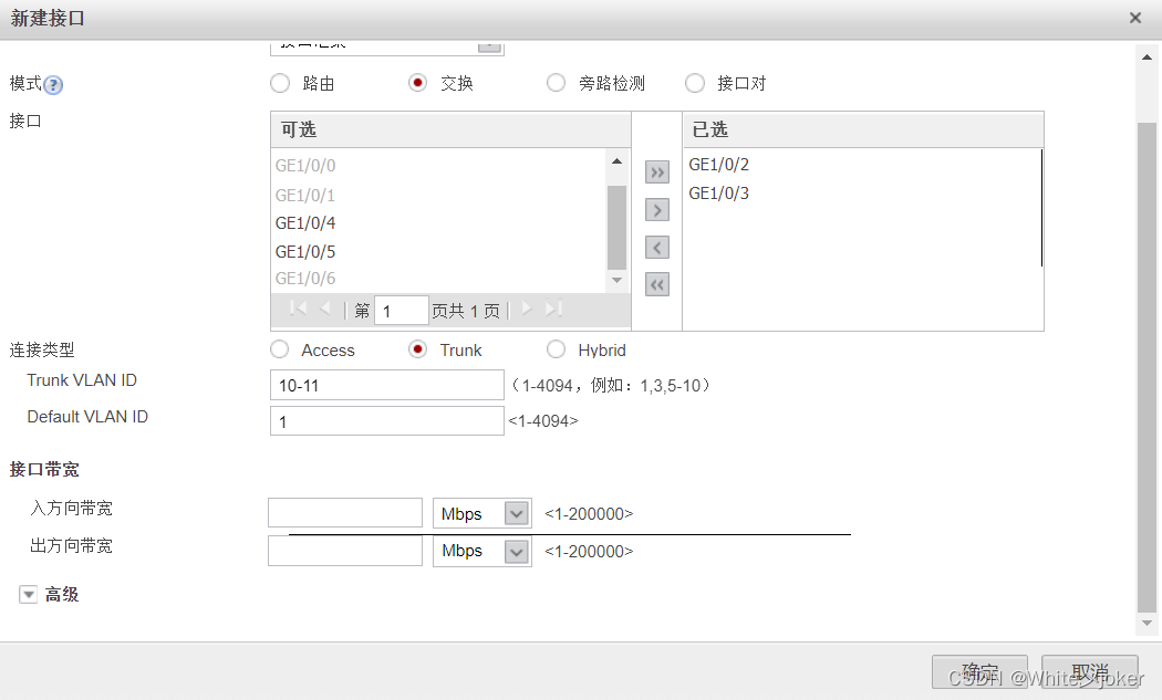
注意:
一般一个网关选择:Access,两个网关选择:Truck
![]()
在LSW2上配置接口聚合
[DMZ]int Eth-Trunk 1
[DMZ-Eth-Trunk1]tru
[DMZ-Eth-Trunk1]trunkport g 0/0/1
[DMZ-Eth-Trunk1]
[DMZ-Eth-Trunk1]trunkport g 0/0/2
[DMZ-Eth-Trunk1]port link-type trunk
[DMZ-Eth-Trunk1]
[DMZ-Eth-Trunk1]port trunk allow-pass vlan 10 to 11
[DMZ-Eth-Trunk1]
[DMZ-Eth-Trunk1]vla
[DMZ-Eth-Trunk1]vlan 10
[DMZ-vlan10]vla
[DMZ-vlan10]vlan 11
[DMZ-vlan11]q
[DMZ]int g 0/0/4
[DMZ-GigabitEthernet0/0/4]port link-type access
[DMZ-GigabitEthernet0/0/4]port default vlan 10
[DMZ-GigabitEthernet0/0/4]
[DMZ-GigabitEthernet0/0/4]int g 0/0/3
[DMZ-GigabitEthernet0/0/3]port link-type access
[DMZ-GigabitEthernet0/0/3]port default vlan 11
[DMZ-GigabitEthernet0/0/3]
在防火墙上创建DMZ上的三层口

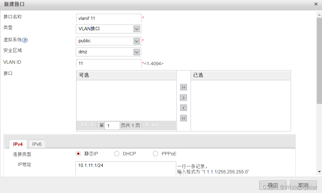
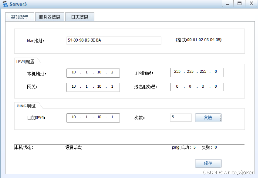
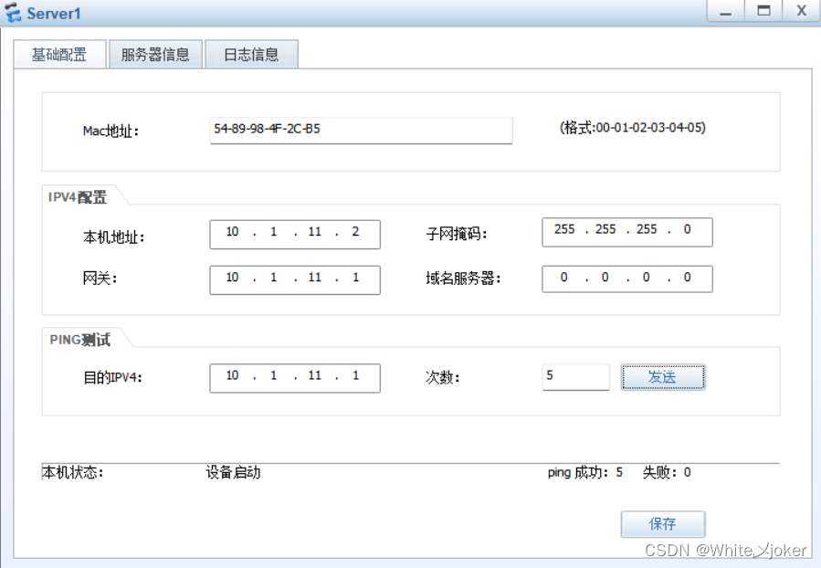
测试
4.区域间互相通
配置路由策略
5.配置接口对

配置GE1/0/4端口
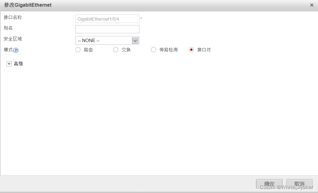
注意:
GE1/0/5端口与GE1/0/4端口相同
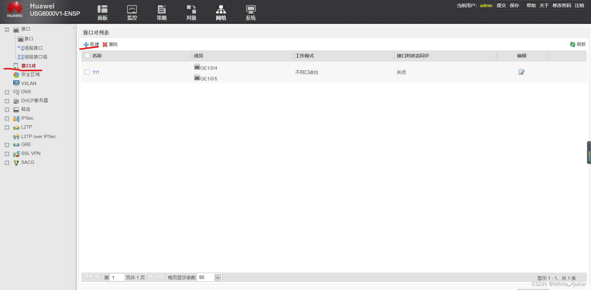
创建接口对

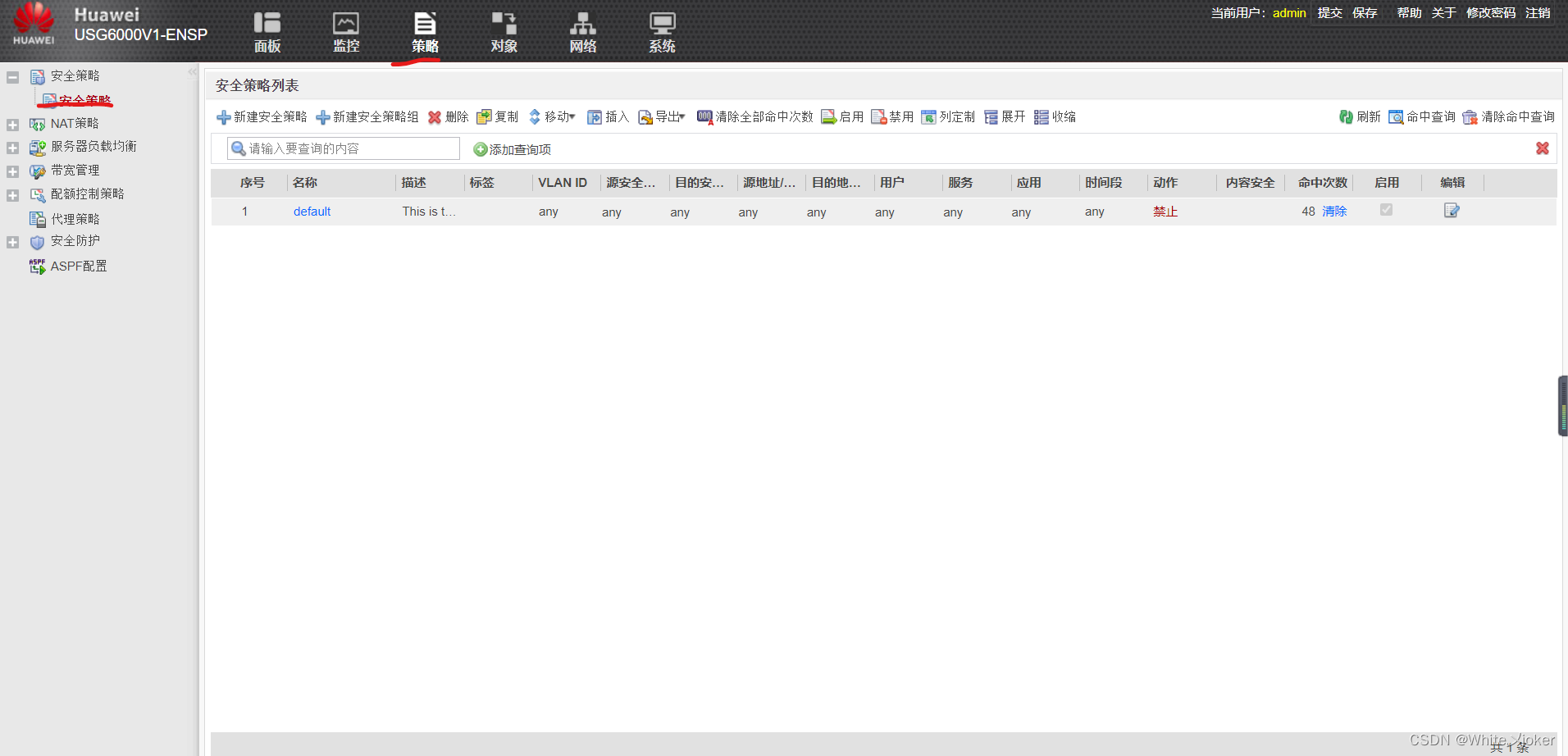
6.防火墙安全策略配置(trust-to-untrust)
新建安全策略

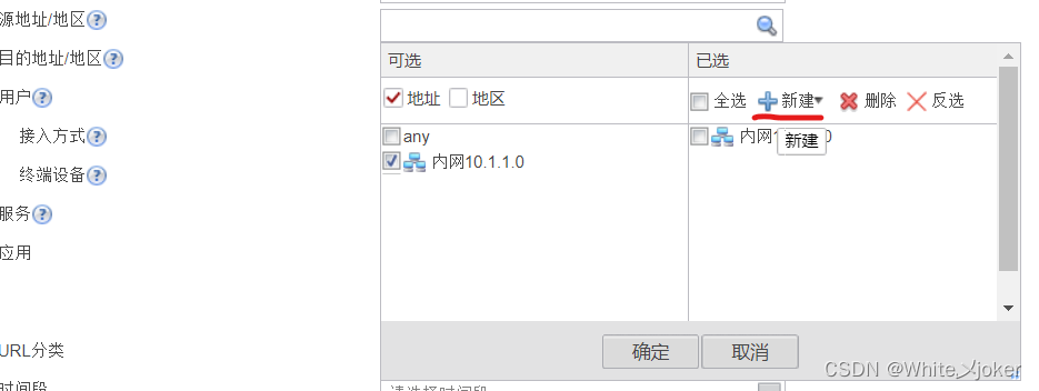
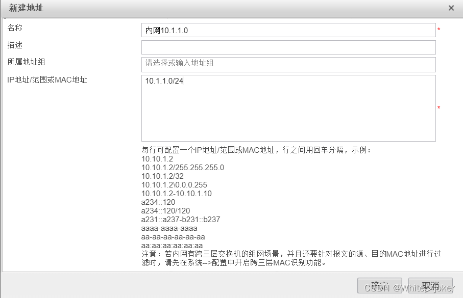
配置原地址
AR1配置回包路由
[ISP]ip router-static 0.0.0.0 0 100.1.1.1LSW1配置回包路由
[LSW1]ip route-static 0.0.0.0 0 10.1.255.2
测试
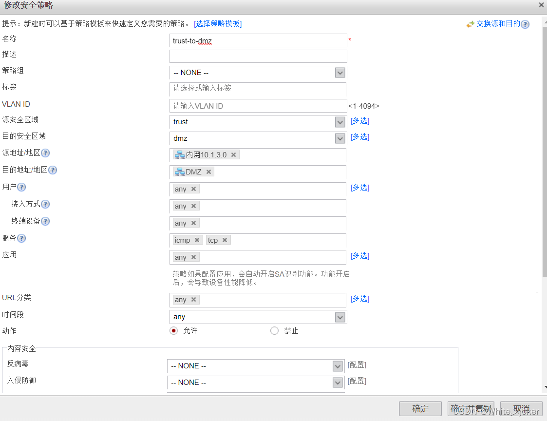
7.防火墙安全策略配置(trust-to-DMZ)
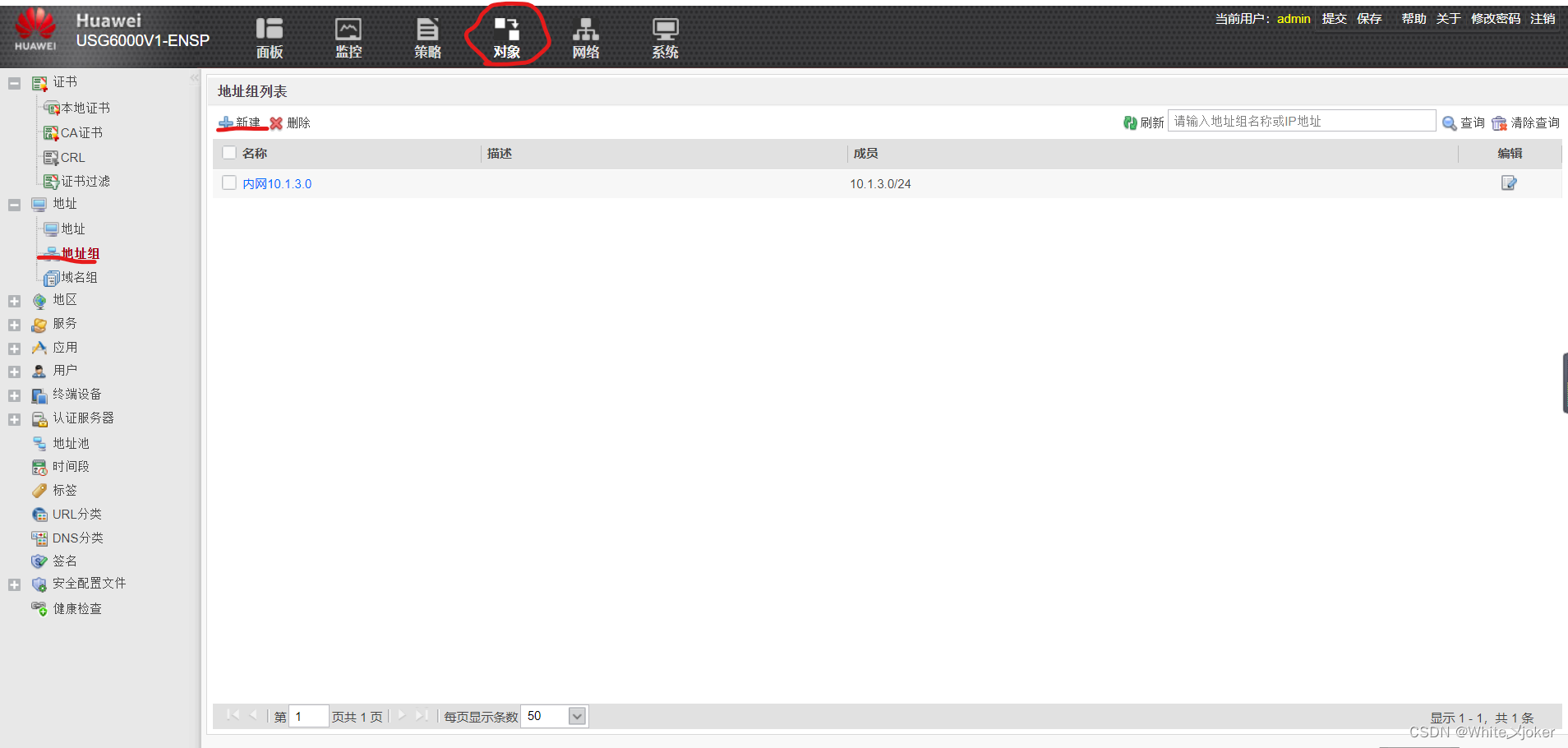
定义地址组
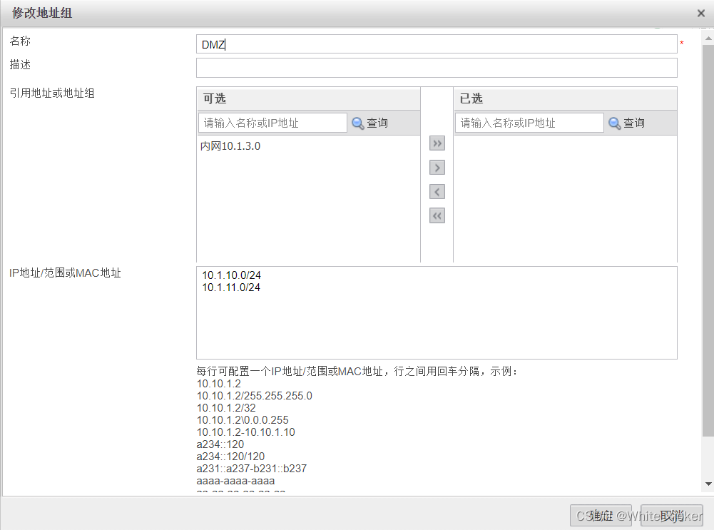
创建安全策略(trust-to-dmz)
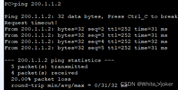
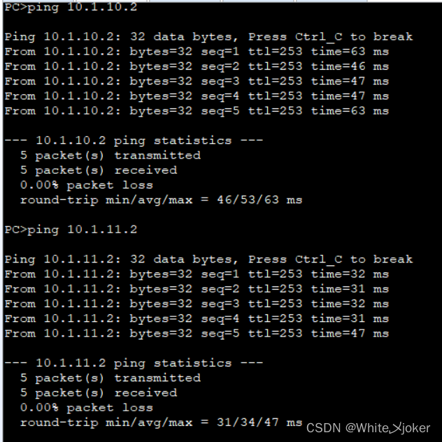
测试
8.防火墙安全策略配置(untrust-to-DMZ)
定义地址
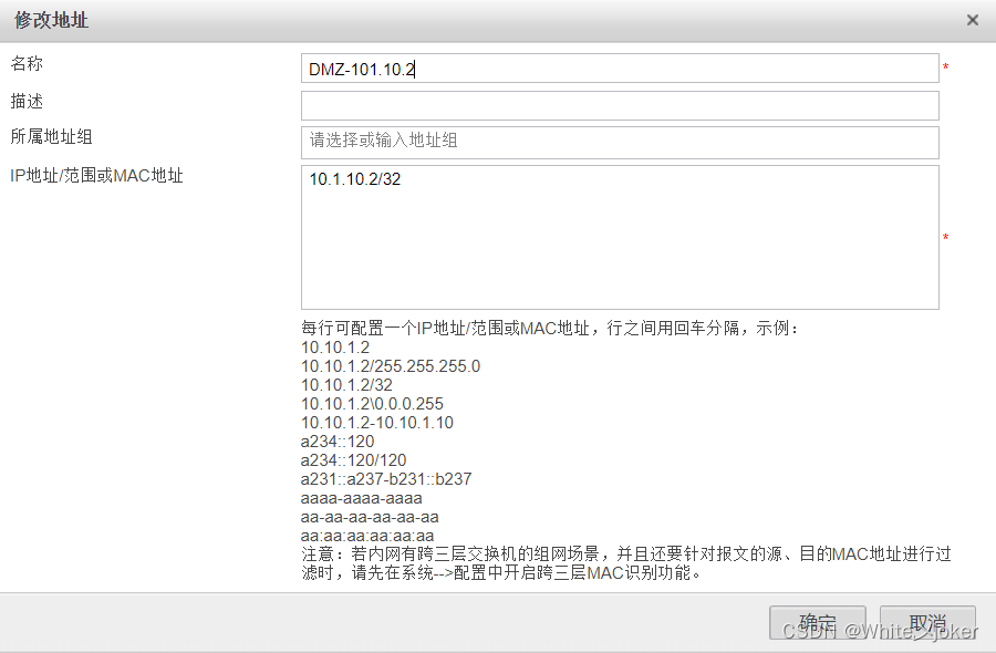
创建安全策略(untrust-to-dmz)
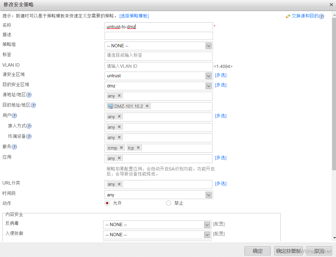
测试
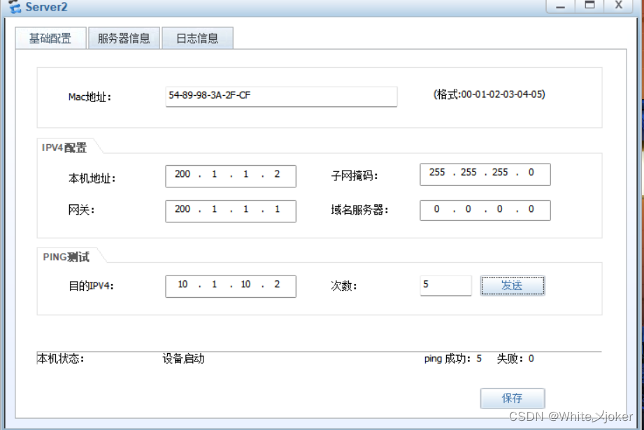
总测试
