origin refer :http://www.songho.ca/opengl/gl_transform.html#modelview
OpenGL 矩阵变换
Related Topics: OpenGL Pipeline, OpenGL Projection Matrix, OpenGL Matrix Class
Download: matrixModelView.zip, matrixProjection.zip
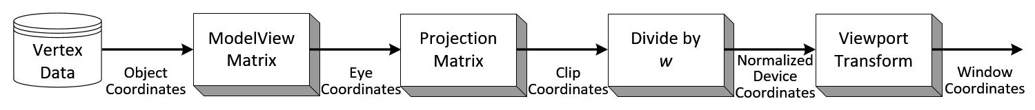
几何数据——如顶点位置,和标准向量(normal vectors),在OpenGL 管道raterization 处理过程之前可通过顶点操作(Vertex Operation)和基本组合操作改变这些数据。
Object Coordinates
对象的本地坐标系——任何变换之前的最初位置.为了变换(transformation)这些对象,可以调用glRotate(),glTranslatef(),glScalef()这些方法。
增加常用坐标系 有助于理解各种坐标的关系《坐标系仅表示相对关系,与具体名称无关》
OpenGL有6种坐标系,分别如下:
- 1,物体或模型坐标系(Object or model coordinates);
- 2,世界坐标系(World coordinates)
- 3,眼坐标或相机坐标(Eye (or Camera) coordinates)
- 4,裁剪坐标系(Clip coordinates)
- 5,标准设备坐标系(Normalized device coordinates)
- 6,屏幕坐标系(Window (or screen) coordinates)
除了上面6种外,OpenGL还存在一种假想坐标系纹理坐标系,这个坐标系是不存在的,它其实是一系列变换矩阵的结果,比如它能使顶点从物体或模型坐标系变换到世界坐标系。
从object coordainates到world coordinates再到camera coordinate的变换,在OpenGL中统一称为model-view转换,初始化的时候,object coordinates和world coordinates还有camera coordinates坐标重合在原点,变换矩阵都为Identity,所以在OpenGL中用glLoadIdentity()初始化变换矩阵栈。model-view matix转换points,vectorsd到camera坐标系。
Eye Coordinates
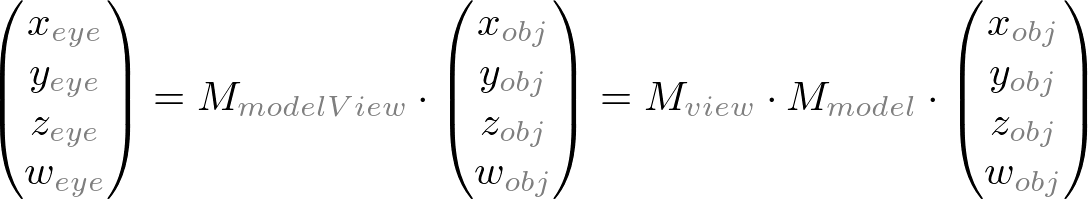
使用GL_MODELVIEW矩阵和Object 坐标相乘所得。在OpenGL中用GL_MODELVIEW将对象对象空间(Object Space)变换到视觉空间(eye space)。GL_MODELVIEW
矩阵是模型矩阵(Model Matrix)和视觉矩阵(View Matrix)的组合 (![]() )。其中,Model 变换指的是将Object Space转换到World Space
)。其中,Model 变换指的是将Object Space转换到World Space
(译注:World Space值得是OpenGL中的三维空间),而View 变换是将World space变换到eye space。
注意:在OpenGL中没有单独的camera(view) matrix。因此,为了模拟camera或者view的变换,其中的场景(3D物体和光照)必须通过和view相反的方向变换。也就是说,OpenGL总是将camera定义在(0,0,0)点,并且强制在eye space坐标系的-Z轴方向,而且不能变换。关于GL_MODELVIEW Matrix的详细资料可以查看此处:http://www.songho.ca/opengl/gl_transform.html#modelview
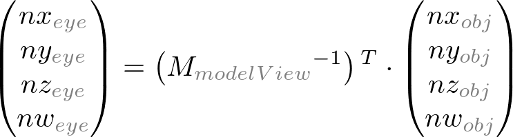
标准向量(Normal vectors)——从对象坐标系(Object coordinates)变换到视觉坐标系(eye coordinates),它是用来计算光照(lighting calculation)的.注意标准向量(Normal vectors)的变换和顶点的不同。其中视觉矩阵(view matrix)是GL_MODELVIEW逆矩阵的转置矩阵和标准向量(Normal vector是)相乘所得,即:
更多关于标准向量变换(Normal Vector Transformation)的资料可连接到此处:http://www.songho.ca/opengl/gl_normaltransform.htm
剪切面坐标系(Clip Coordinates)
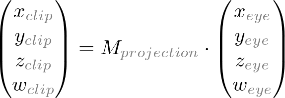
视觉坐标系和GL_PROJECTION矩阵相乘,得到剪切面坐标系。GL_PROJECTION矩阵定义了可视的空间(截头锥体)(译注:关于什么是截头锥体,我还查了下资料,发现它是这个样子的:

,这个就是投影的效果啦)以及顶点数据如何投影到屏幕上(视角或者正交化(orthogonal)),它被称为剪切面坐标系的原因是(x,y,z)变换之后
要和±w比较。更多关于GL_PROJECTION矩阵的资料可见:http://www.songho.ca/opengl/gl_transform.html#projection
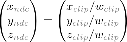
标准化设备坐标系(NDC)
将剪切面坐标系除以w所得(关于w的讨论可见此处:,http://www.songho.ca/math/homogeneous/homogeneous.html),它被称为视角除法(perspective division)
.它更像是窗口坐标系,只是还没有转换或者缩小到屏幕像素。其中它取值范围在3个轴向从-1到1标准化了。
窗口坐标系(Window Coordinates)/屏幕坐标系(Screen Coordinates)
将标准化设备坐标系(NDC)应用于视口转换。NDC将缩小和平移以便适应屏幕的透视。窗口坐标系最终传递给OpenGL的管道处理变成了fragment。glViewPort()函数
用来定义最终图片映射的投影区域。同样,glDepthRange()用来决定窗口坐标系的z坐标。窗口坐标系由下面两个方法给出的参数计算出来
glViewPort(x,y,w,h);
glDepthRange(n,f);
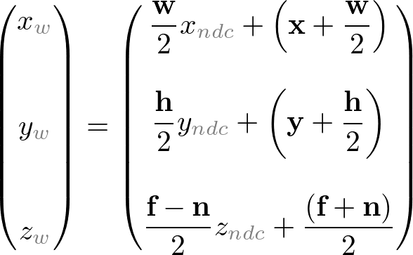
视口转换公式很简单,通过NDC和窗口坐标系的线性关系得到:
![]()
OpenGL 转换矩阵
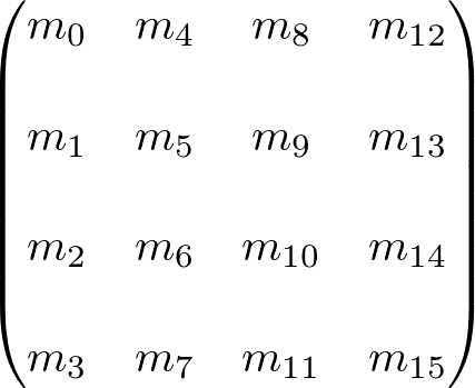
OpenGL使用4x4矩阵变换。注意,这16个元素存储在1D数组中,这些元素按列顺序排列。假如你想以行为顺序排列,你需要转置该矩阵。
OpenGL有4中不用的矩阵:GL_MODELVIEW,GL_PROJECTION,GL_TEXTURE和GL_COLOR.你可以在
代码中使用glMatrixMode()函数改变当前的类型。例如,为了选择GL_MODELVIEW矩阵,可以这样:
glMatrixMode(GL_MODELVIEW);
---------------------------------------------------------------------------------------------------------------------------------------------
Model-View 矩阵(GL_MODELVIEW)
GL_MODELVIEW矩阵在一个矩阵中包含view矩阵和model 矩阵,为了变换view(camera),你需要将整个
场景施以逆变换。gluLookAt()用来设置viewing变换。
最右边的三个矩阵元素 (m12, m13, m14) 是用作位移变换的。m15元素是齐次坐标。(何为齐次坐标,参见:http://www.songho.ca/math/homogeneous/homogeneous.html),该元素是用来投影变换的。
(注意这三个元素集实际上指得是3个正交坐标系:
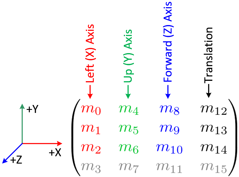
4 columns of GL_MODELVIEW matrix
我们能够不使用OpenGL变换函数,直接构造GL_MODELVIEW矩阵。下面有一些有用的代码构建GL_MODELVIEW矩阵
1. Angles to Axes
2. Lookat to Axes
3. Matrix4 class
注意,OpenGL在多种变换同时施加到顶点上时以相反的顺序矩阵相乘。例如,假如一个顶点先以MA
x
![]()

投影矩阵Projection Matrix(GL_PROJECTION)
GL_PROJECTION矩阵用来定义截锥体。该截锥体决定了那些对象或者对象的哪些部分将会被裁剪掉。同样,它也决定着3D场景怎样投影到屏幕中
(关于怎样构建投影矩阵,请查看
http://www.songho.ca/opengl/gl_projectionmatrix.html
OpenGL提供2个函数用来GL_PROJECTION变换。glFrustum()产生投影视角。glOrtho()产生正交(或者平行)投影。
两个函数都需要6个参数决定6个剪切面:left, right, bottom, top, near, 和far 平面。截锥体的8个顶点如下所示:
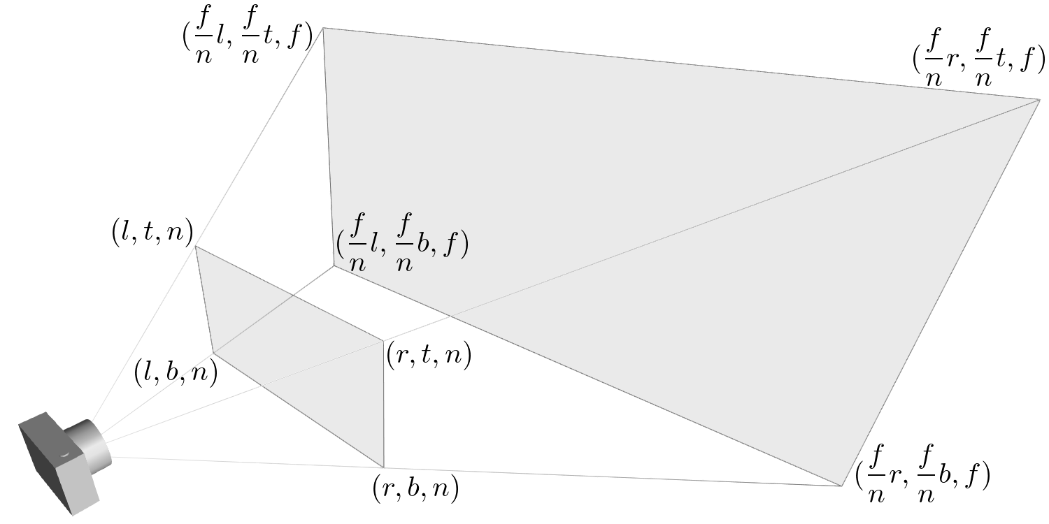
OpenGL Perspective Viewing Frustum
远端平面(后面)的顶点能够简单地通过相似三角形的比率计算出来。例如,远端平面的左侧可以如下计算:
![]()
对于正交投影,ratio为1,所以远端平面的left,right,bottom和top值都与近端平面的值相同。
、//OpenGL ES中常用到的几种坐标系:世界坐标系、物体坐标系、设备坐标系、眼坐标系当然还有假想的纹理坐标系
同样,你也可以使用gluPerspective()和gluOrtho2D()函数,但是传递更少的参数。gluPerspective()只需要4个参数:视图的垂直区域(vertical field of view(FOV)),
width/height的ratio,还有近端平面和远端平面的距离。下面代码使用gluPerspective()和glFrustum()实现同样的功能:

OpenGL正交的截锥体
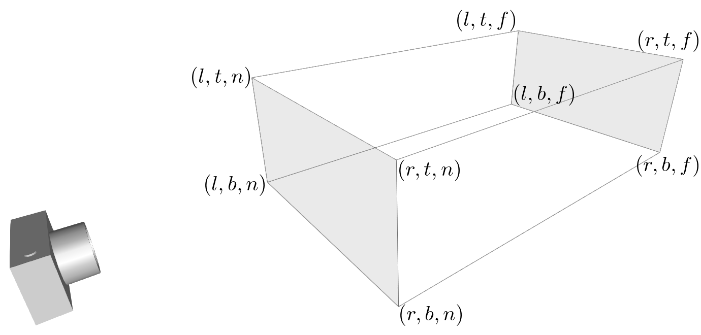
OpenGL Orthographic Frustum
然而,假如你想要一个非对称的视觉空间,你可以直接使用glFrustum()。例如,
假如你想要呈现一个大的场景到2个相邻的屏幕,你可以截断截锥体变成2个不对称的截锥体(左和右)。然后,
呈现每个截锥体场景。
(这句话太不好翻译了,原位如下:
For example, if you want to render a wide scene into 2 adjoining screens, you can break down the frustum into 2 asymmetric frustums (left and right). Then, render the scene with each frustum.
![]()
An example of an asymmetric frustum
纹理矩阵(GL_TEXTURE)
纹理坐标(s,t,r,q)在任何纹理映射之前乘以GL_TEXTURE矩阵所得,默认是恒等的。所以纹理映射到物体的位置将正好是你赋值给纹理坐标的位置。
通过改变GL_TEXTURE,你可以滑动,旋转,拉伸或者伸缩纹理。

颜色矩阵(GL_COLOR)
颜色部分是通过乘以GL_COLOR矩阵所得。该矩阵用于颜色空间和颜色组件的变换。(原位如下:It can be used for color space conversion and color component swaping)
颜色矩阵并不是通用的,需要GL_ARB_imaging扩展(什么是GL_ARB_imaging扩展?求解)
其他矩阵例子
glPushMatrix()——将当前的矩阵压入矩阵栈
glPopMatrix()——从当前的矩阵栈中弹出当前的矩阵
glLoadIdentity()——设置当前矩阵为等同矩阵
glLoadMatrix{fd}(m)——将当前矩阵替换成矩阵m
glLoadTransposeMatrix{fd}(m)——将当前矩阵换成其转置矩阵
glMultMatrix{fd}(m)——将当前矩阵乘以矩阵m,并且更新当前矩阵
glMultTransposeMatrix{fd}(m)——将当前矩阵乘以其转置矩阵,并且更新当前矩阵
glGetFloatv(GL_MODELVIEW_MATRIX, m) ——将GL_MODELVIEW矩阵的16个值加载到m中
例子1:ModelView Matrix

这个demo应用显示怎样使用glTranslatef()和glRotatef()操作GL_MODELVIEW
下载链接:
matrixModelView.zip:
http://www.songho.ca/opengl/files/matrixModelView.zip
(OS X 10.6+) matrixModelView_mac.zip: http://www.songho.ca/opengl/files/matrixModelView_mac.zip
注意所有的OpenGL函数在Mac和Windows下都在ModelGL.h和ModelGL.cpp中实现,在这些包中的这些文件是完全一样的。
该demo应用使用一个定制的4X4类(链接为:http://www.songho.ca/opengl/gl_matrix.html)作为默认的OpenGL矩阵例子,为了指定model和camera变换.
在ModelGL.cpp中有3中矩阵对象:matrixModel,matrixView和matrixModelView.每一种矩阵保存着预先计算好的变换。然后将这些矩阵元素传递给OpenGL的函数——glLoadMatrix().实际的画图程序应该向下面这个样子:

使用OpenGL默认的矩阵函数,相同的代码如下:

投影矩阵例子:

该 demo应用显示了如何使用glFrustum()和glOrtho()函数操作投影变换。
源码和二进制文件下载的链接:
matrixProjection.zip:
http://www.songho.ca/opengl/files/matrixProjection.zip
matrixProjection_mac.zip(OS X 10.6+):
http://www.songho.ca/opengl/files/matrixProjection_mac.zip
同样,ModelGL.h和ModelGL.cpp在两者的包中有同样的文件,且所有的OpenGL函数都置于这些文件中。
ModelGL类有一个定制的matrix对象:matrixProjection,两个成员函数:setFrustum()和setOrthoFrustum().
其功能与glFrustum()和glOrtho()函数相同

GL_PROJECTION矩阵构建的16个参数在这可以看到:
http://www.songho.ca/opengl/gl_projectionmatrix.html
OpenGL Transformation
Related Topics: OpenGL Pipeline, OpenGL Projection Matrix, OpenGL Matrix Class
Download: matrixModelView.zip, matrixProjection.zip
Overview
Geometric data such as vertex positions and normal vectors are transformed via Vertex Operation and Primitive Assembly operation in OpenGL pipeline before raterization process.
Object Coordinates
It is the local coordinate system of objects and is initial position and orientation of objects before any transform is applied. In order to transform objects, use glRotatef(), glTranslatef(), glScalef().
Eye Coordinates
It is yielded by multiplying GL_MODELVIEW matrix and object coordinates. Objects are transformed from object space to eye space using GL_MODELVIEW matrix in OpenGL. GL_MODELVIEW matrix is a combination of Model and View matrices (![]() ). Model transform is to convert from object space to world space. And, View transform is to convert from world space to eye space.
). Model transform is to convert from object space to world space. And, View transform is to convert from world space to eye space.
![]()
Note that there is no separate camera (view) matrix in OpenGL. Therefore, in order to simulate transforming the camera or view, the scene (3D objects and lights) must be transformed with the inverse of the view transformation. In other words, OpenGL defines that the camera is always located at (0, 0, 0) and facing to -Z axis in the eye space coordinates, and cannot be transformed. See more details of GL_MODELVIEW matrix inModelView Matrix.
Normal vectors are also transformed from object coordinates to eye coordinates for lighting calculation. Note that normals are transformed in different way as vertices do. It is mutiplying the tranpose of the inverse of GL_MODELVIEW matrix by a normal vector. See more details in Normal Vector Transformation.
Clip Coordinates
The eye coordinates are now multiplied with GL_PROJECTION matrix, and become the clip coordinates. This GL_PROJECTION matrix defines the viewing volume (frustum); how the vertex data are projected onto the screen (perspective or orthogonal). The reason it is called clip coordinates is that the transformed vertex (x, y, z) is clipped by comparing with ±w.
See more details of GL_PROJECTION matrix in Projection Matrix.
Normalized Device Coordinates (NDC)
It is yielded by dividing the clip coordinates by w. It is called perspective division. It is more like window (screen) coordinates, but has not been translated and scaled to screen pixels yet. The range of values is now normalized from -1 to 1 in all 3 axes.
Window Coordinates (Screen Coordinates)
It is yielded by applying normalized device coordinates (NDC) to viewport transformation. The NDC are scaled and translated in order to fit into the rendering screen. The window coordinates finally are passed to the raterization process of OpenGL pipeline to become a fragment. glViewport() command is used to define the rectangle of the rendering area where the final image is mapped. And, glDepthRange() is used to determine the z value of the window coordinates. The window coordinates are computed with the given parameters of the above 2 functions;
glViewport(x, y, w, h);
glDepthRange(n, f);
The viewport transform formula is simply acquired by the linear relationship between NDC and the window coordinates; ![]()
OpenGL Transformation Matrix
OpenGL Transform Matrix
OpenGL uses 4 x 4 matrix for transformations. Notice that 16 elements in the matrix are stored as 1D array in column-major order. You need to transpose this matrix if you want to convert it to the standard convention, row-major format.
OpenGL has 4 different types of matrices; GL_MODELVIEW, GL_PROJECTION, GL_TEXTURE, and GL_COLOR. You can switch the current type by using glMatrixMode() in your code. For example, in order to select GL_MODELVIEW matrix, use glMatrixMode(GL_MODELVIEW).
Model-View Matrix (GL_MODELVIEW)
GL_MODELVIEW matrix combines viewing matrix and modeling matrix into one matrix. In order to transform the view (camera), you need to move whole scene with the inverse transformation. gluLookAt() is particularly used to set viewing transform.
4 columns of GL_MODELVIEW matrix
The 3 matrix elements of the rightmost column (m12, m13, m14) are for the translation transformation, glTranslatef(). The element m15 is the homogeneous coordinate. It is specially used for projective transformation.
3 elements sets, (m0, m1, m2), (m4, m5, m6) and (m8, m9, m10) are for Euclidean and affine transformation, such as rotation glRotatef() or scaling glScalef(). Note that these 3 sets are actually representing 3 orthogonal axes;
- (m0, m1, m2) : +X axis, left vector, (1, 0, 0) by default
- (m4, m5, m6) : +Y axis, up vector, (0, 1, 0) by default
- (m8, m9, m10) : +Z axis, forward vector, (0, 0, 1) by default
We can directly construct GL_MODELVIEW matrix from angles or lookat vector without using OpenGL transform functions. Here are some useful codes to build GL_MODELVIEW matrix:
Note that OpenGL performs matrices multiplications in reverse order if multiple transforms are applied to a vertex. For example, If a vertex is transformed by MA first, and transformed by MB second, then OpenGL performs MB x MA first before multiplying the vertex. So, the last transform comes first and the first transform occurs last in your code. ![]()
// Note that the object will be translated first then rotated
glRotatef(angle, 1, 0, 0);   // rotate object angle degree around X-axis
glTranslatef(x, y, z);       // move object to (x, y, z)
drawObject();
Projection Matrix (GL_PROJECTION)
GL_PROJECTION matrix is used to define the frustum. This frustum determines which objects or portions of objects will be clipped out. Also, it determines how the 3D scene is projected onto the screen. (Please see more details how to construct the projection matrix.)
OpenGL provides 2 functions for GL_PROJECTION transformation. glFrustum() is to produce a perspective projection, and glOrtho() is to produce a orthographic (parallel) projection. Both functions require 6 parameters to specify 6 clipping planes; left, right, bottom, top, near and far planes. 8 vertices of the viewing frustum are shown in the following image.
OpenGL Perspective Viewing Frustum
The vertices of the far (back) plane can be simply calculated by the ratio of similar triangles, for example, the left of the far plane is; ![]()
OpenGL Orthographic Frustum
For orthographic projection, this ratio will be 1, so the left, right, bottom and top values of the far plane will be same as on the near plane.
You may also use gluPerspective() and gluOrtho2D() functions with less number of parameters. gluPerspective() requires only 4 parameters; vertical field of view (FOV), the aspect ratio of width to height and the distances to near and far clipping planes. The equivalent conversion from gluPerspective() to glFrustum() is described in the following code.
// This creates a symmetric frustum.
// It converts to 6 params (l, r, b, t, n, f) for glFrustum()
// from given 4 params (fovy, aspect, near, far)
void makeFrustum(double fovY, double aspectRatio, double front, double back)
{
    const double DEG2RAD = 3.14159265 / 180;

    double tangent = tan(fovY/2 * DEG2RAD);   // tangent of half fovY
    double height = front * tangent;          // half height of near plane
    double width = height * aspectRatio;      // half width of near plane

    // params: left, right, bottom, top, near, far
    glFrustum(-width, width, -height, height, front, back);
}
An example of an asymmetric frustum
However, you have to use glFrustum() directly if you need to create a non-symmetrical viewing volume. For example, if you want to render a wide scene into 2 adjoining screens, you can break down the frustum into 2 asymmetric frustums (left and right). Then, render the scene with each frustum.
Texture Matrix (GL_TEXTURE)
Texture coordinates (s, t, r, q) are multiplied by GL_TEXTURE matrix before any texture mapping. By default it is the identity, so texture will be mapped to objects exactly where you assigned the texture coordinates. By modifying GL_TEXTURE, you can slide, rotate, stretch, and shrink the texture.
// rotate texture around X-axis
glMatrixMode(GL_TEXTURE);
glRotatef(angle, 1, 0, 0);
Color Matrix (GL_COLOR)
The color components (r, g, b, a) are multiplied by GL_COLOR matrix. It can be used for color space conversion and color component swaping. GL_COLOR matrix is not commonly used and is required GL_ARB_imagingextension.
Other Matrix Routines
Example: ModelView Matrix
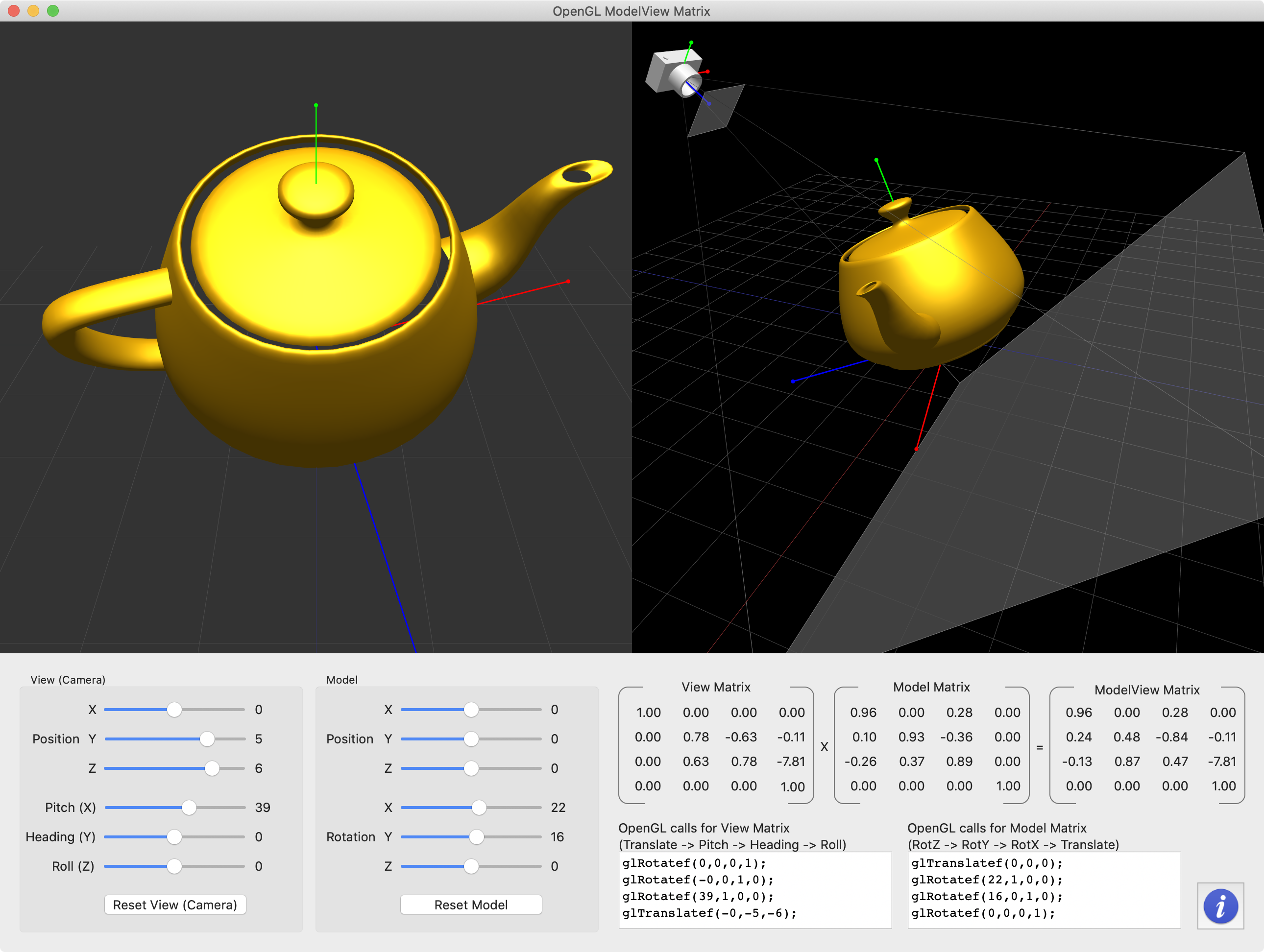
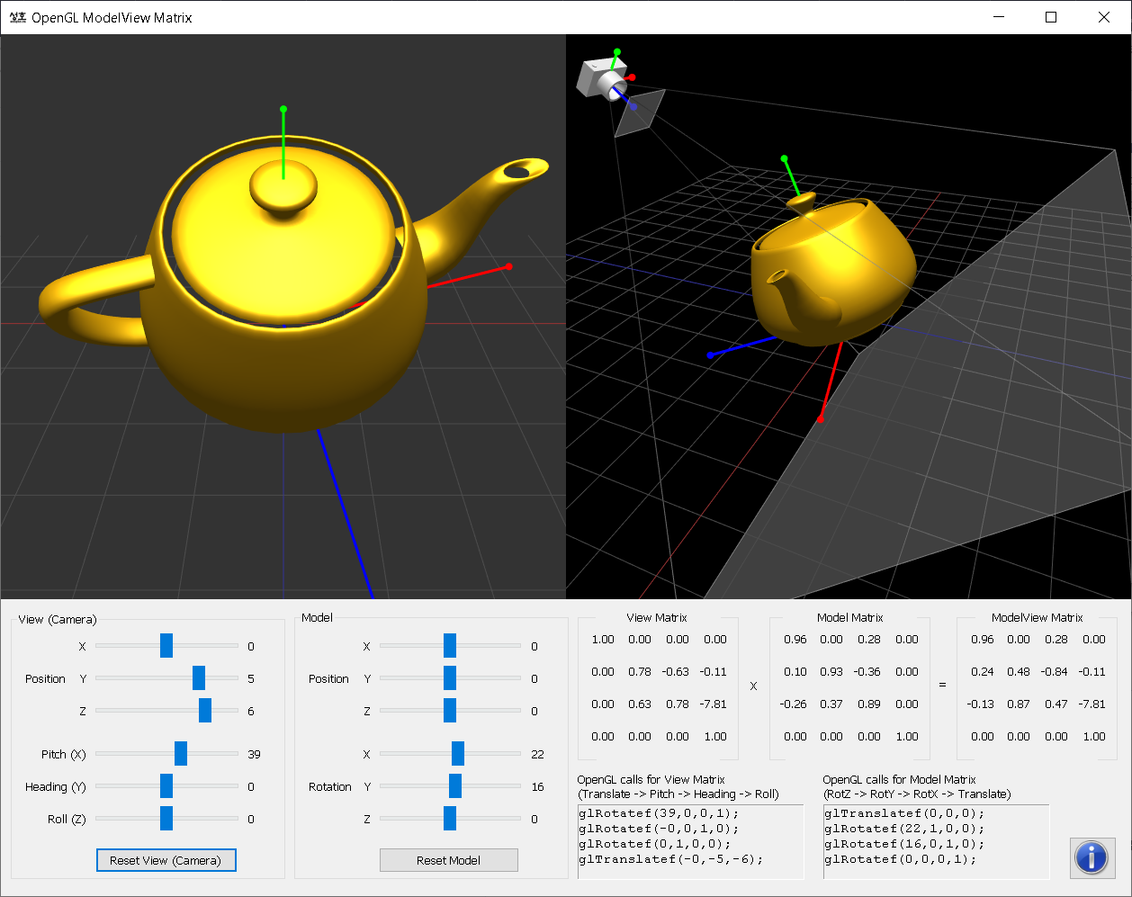
This demo application shows how to manipulate GL_MODELVIEW matrix by translation and rotation transforms.
Download the source and binary:
(Updated: 2018-04-16)
![]() matrixModelView.zip (include VS 2015 project)
matrixModelView.zip (include VS 2015 project) ![]() matrixModelView_mac.zip (macOS 10.10+, include Xcode v9)
matrixModelView_mac.zip (macOS 10.10+, include Xcode v9)
Note that all OpenGL function calls are implemented in ModelGL.h and ModelGL.cpp on both Mac and Windows versions, and these files are identical on both packages (platform independent).
This demo application uses a custom 4x4 matrix class as well as default OpenGL matrix routines in order to specify model and camera transforms. There are 3 of matrix objects defined in ModelGL.cpp; matrixModel, matrixView and matrixModelView. Each matrix stores the pre-computed transformation and passes the matrix elements to OpenGL by using glLoadMatrixf(). The actual drawing routine looks like;
...
glPushMatrix();

// set view matrix for camera transform
glLoadMatrixf(matrixView.get());

// draw the grid at origin before model transform
drawGrid();

// set modelview matrix for both model and view transform
// It transforms from object space to eye space.
glLoadMatrixf(matrixModelView.get());

// draw a teapot after both view and model transforms
drawTeapot();

glPopMatrix();
...
The equivalent code using default OpenGL matrix functions is;
...
glPushMatrix();

// initialze ModelView matrix
glLoadIdentity();

// First, transform the camera (viewing matrix) from world space to eye space
// Notice translation and heading values are negated,
// because we move the whole scene with the inverse of camera transform
// ORDER: translation -> roll -> heading -> pitch
glRotatef(cameraAngle[2], 0, 0, 1);  // roll
glRotatef(-cameraAngle[1], 0, 1, 0); // heading
glRotatef(cameraAngle[0], 1, 0, 0);  // pitch
glTranslatef(-cameraPosition[0], -cameraPosition[1], -cameraPosition[2]);

// draw the grid at origin before model transform
drawGrid();

// transform the object (model matrix)
// The result of GL_MODELVIEW matrix will be:
// ModelView_M = View_M * Model_M
// ORDER: rotZ -> rotY -> rotX -> translation
glTranslatef(modelPosition[0], modelPosition[1], modelPosition[2]);
glRotatef(modelAngle[0], 1, 0, 0);
glRotatef(modelAngle[1], 0, 1, 0);
glRotatef(modelAngle[2], 0, 0, 1);

// draw a teapot with model and view transform together
drawTeapot();

glPopMatrix();
...
Example: Projection Matrix
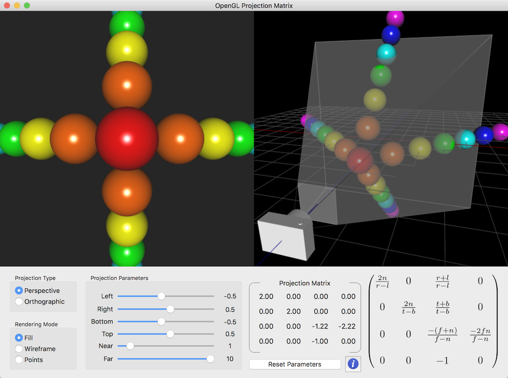
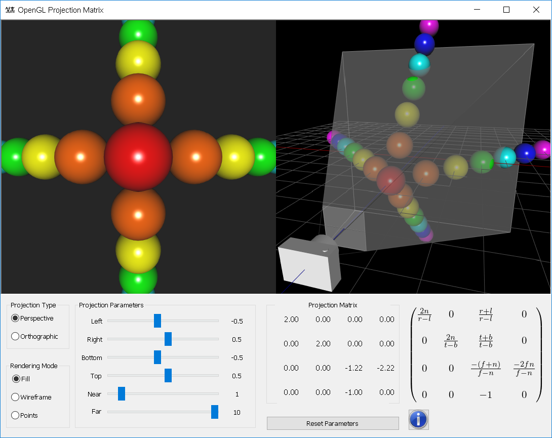
This demo application is to show how to manipulate the projection transformation with 6 parameters; left, right, bottom, top, near and far values.
Download the source and binary:
(Updated: 2017-03-15)
![]() matrixProjection.zip (include VS 2015 project)
matrixProjection.zip (include VS 2015 project) ![]() matrixProjection_mac.zip (macOS 10.10+, include Xcode v9)
matrixProjection_mac.zip (macOS 10.10+, include Xcode v9)
Again, ModelGL.h and ModelGL.cpp are exactly same files on both packages (platform independent), and all OpenGL function calls are placed in these files.
ModelGL class has a custom matrix object, matrixProjection, and 2 member functions, setFrustum() and setOrthoFrustum(), which are equivalent to glFrustum() and glOrtho().
///////////////////////////////////////////////////////////////////////////////
// return a perspective frustum with 6 params similar to glFrustum()
// (left, right, bottom, top, near, far)
///////////////////////////////////////////////////////////////////////////////
Matrix4 ModelGL::setFrustum(float l, float r, float b, float t, float n, float f)
{
    Matrix4 matrix;
    matrix[0]  =  2 * n / (r - l);
    matrix[5]  =  2 * n / (t - b);
    matrix[8]  =  (r + l) / (r - l);
    matrix[9]  =  (t + b) / (t - b);
    matrix[10] = -(f + n) / (f - n);
    matrix[11] = -1;
    matrix[14] = -(2 * f * n) / (f - n);
    matrix[15] =  0;
    return matrix;
}

///////////////////////////////////////////////////////////////////////////////
// return a symmetric perspective frustum with 4 params similar to
// gluPerspective() (vertical field of view, aspect ratio, near, far)
///////////////////////////////////////////////////////////////////////////////
Matrix4 ModelGL::setFrustum(float fovY, float aspectRatio, float front, float back)
{
    float tangent = tanf(fovY/2 * DEG2RAD);   // tangent of half fovY
    float height = front * tangent;           // half height of near plane
    float width = height * aspectRatio;       // half width of near plane

    // params: left, right, bottom, top, near, far
    return setFrustum(-width, width, -height, height, front, back);
}

///////////////////////////////////////////////////////////////////////////////
// set a orthographic frustum with 6 params similar to glOrtho()
// (left, right, bottom, top, near, far)
///////////////////////////////////////////////////////////////////////////////
Matrix4 ModelGL::setOrthoFrustum(float l, float r, float b, float t, float n, float f)
{
    Matrix4 matrix;
    matrix[0]  =  2 / (r - l);
    matrix[5]  =  2 / (t - b);
    matrix[10] = -2 / (f - n);
    matrix[12] = -(r + l) / (r - l);
    matrix[13] = -(t + b) / (t - b);
    matrix[14] = -(f + n) / (f - n);
    return matrix;
}
...

// how to pass projection matrx to OpenGL
Matrix4 projectionMatrix = setFrustum(l, r, b, t, n, f);
glMatrixMode(GL_PROJECTION);
glLoadMatrixf(matrixProjection.get());
...
Constructing 16 elements of GL_PROJECTION matrix is explained here.