
1 引言
想起去年元旦收到群里面小伙伴儿的建议,希望我们也能够出一个基于NVIDIA Jetson nano 的ROS小车搭建过程,于是我们就慢慢书写了前面已经发布的推文集:
-
《开源!手把手教你搭建Arduino+英伟达Jetson的ROS小车(上)》中,我们介绍了一台Jetson nano小车所需要的硬件部分;
-
《开源!手把手教你驱动Arduino+ROS小车的电机》中,我们介绍了如何使用Arduino及配套的扩展板实现两个直流减速电机的差速控制;
-
《开源!手把手教你如何调节编码电机速度PID》中,我们分享了如何通过Arduino自带的串口绘图器完成电机的PID调速。
-
《开源!手把手教你驱动Arduino+ROS小车大功率直流霍尔编码电机》中,我们分享了如何通过Arduino驱动大功率的直流霍尔编码电机。
-
《开源!手把手教你搭建Arduino+英伟达Jetson的ROS小车(中)》中,我们分享了如何将Arduino开发板和英伟达等装配有ROS Melodic 的“上位机”中调试相应的ROS包,完成相应的控制和发布数据。
-
《开源!手把手教你将超声波数据用Rviz可视化》中,介绍了如何使用我们在Arduino 扩展板上预留的超声波接口驱动传感器,将获得的数据在Rviz中用ROS Topic的方式可视化。
在这个过程中,也有小伙伴儿咨询为啥没有基于STM32的底层驱动讲解,这里说明一下我们当时的原由:
-
我们是有计划在后续分享和发布STM32版本的控制器;
-
前期使用Arduino的目的是考虑到部分学习ROS的小伙伴儿非电子专业,对操作寄存器编程方式不熟练,所以使用Arduino作为底层控制板,来讲解整个ROS小车的搭建过程,可以大大降低学习和入门难度;
-
Arduino本身就是一个开源的项目,我们也想借助它,让我们的开源社区可以更加壮大,有更多的人能通过模块化以及低成本的方式接触机器人,熟悉ROS开发;
-
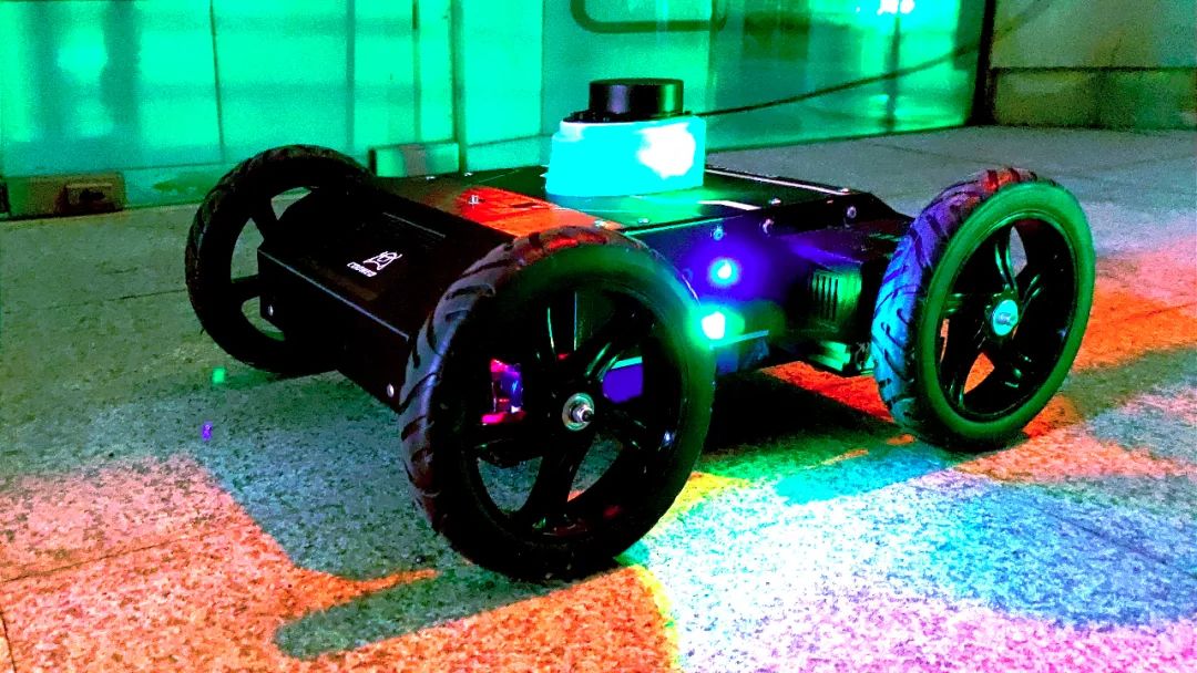
最后,我们也想在基于 NEOR mini 开源无人车仿真平台的基础上,陆陆续续再开源一款基于Arduino底层控制器的真车NEOR mini,这个目标现在已经基本实现。已经完成了基本的功能测试。提前给大家放一张夜晚的图:
上述所提到的一切都是基于Arduino mega 2560 及专用的扩展板开发而来的结果,起初,我们的扩展板仅仅是为了简化单片机和其他部件的连线:
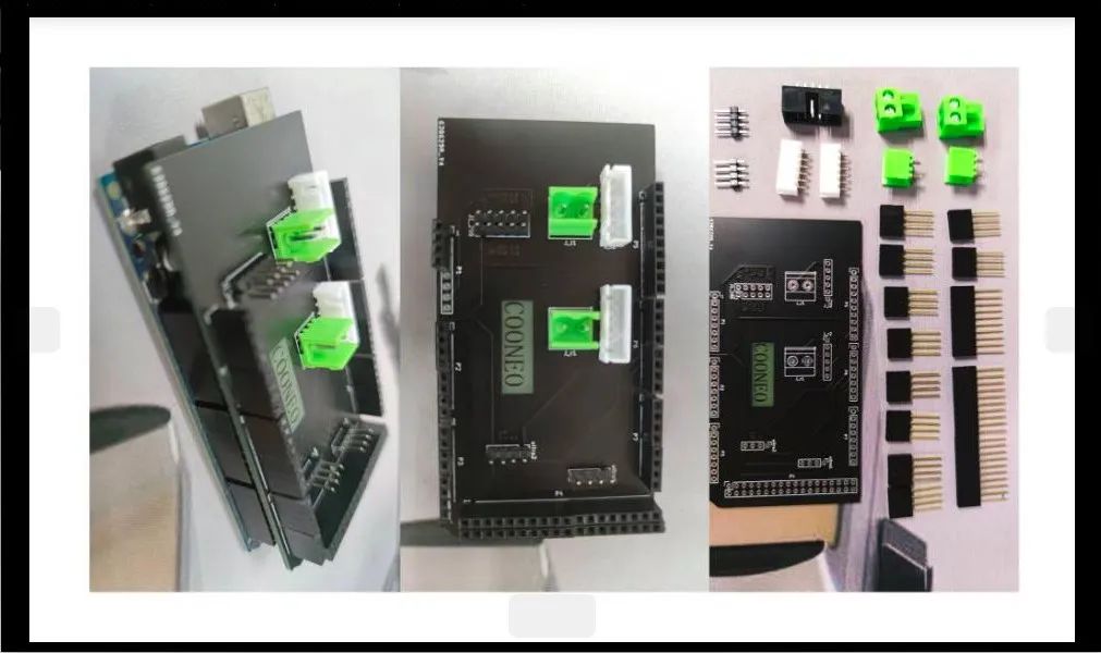
后来,在多位小伙伴的支持与鼓励下,我们在这之上添加了板载5V/3A供电,为新增的两路舵机输出提供足够的电流;
再到后来,越来越多的小伙伴想通过我们发布的《2021年度免费开放资源分享——从零开始搭建ROS小车系列》推文,自己动手做一辆树莓派ROS小车,并且咨询我们有关电机驱动部分。于是乎我们便直接将TB6612FNG模块儿以排母结合的方式集成到了扩展板上。

到此,这块Arduino mega 2560 扩展板成功运用在了二自由度云台、两轮差速、阿克曼ROS小车的底盘上。所以通过上述的推文分享和开源代码,我想大家已经可以和我一样自己动手搭建一辆ROS小车底盘了。
在余下的推文中,我们将分享基于最新版本的Jetson nano主机,复现ROS中经典的建图、导航、CSI摄像头驱动示例。
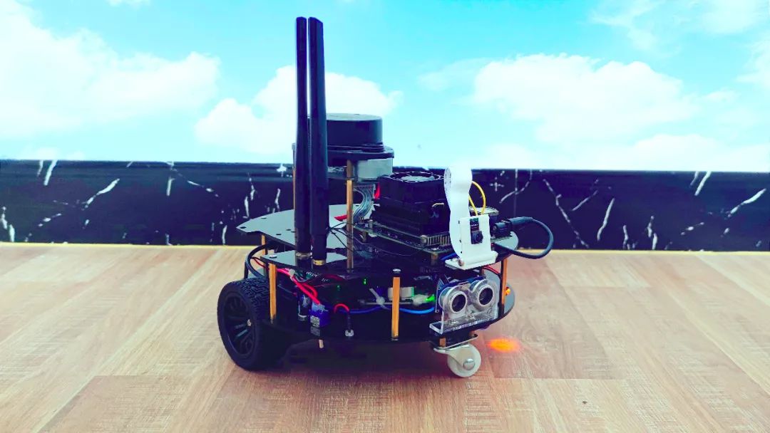
(全套亚克力-37电机版本)
2 软硬件平台
-
硬件
最新版本 Jetson Nano(工业级 , 2路CSI接口)
最新版本思岚雷达(A1M8)
9Dof IMU (带磁力计)
Arduino 版本的两轮差速底盘
-
软件
Arduino IDE + C 语言 开发的底层电机驱动;
适配 Jetson nano 的Ubuntu 操作系统;
ROS melodic + gcam 摄像头驱动;
3 Gmapping 实车建图
Gmapping 订阅雷达测距数据、里程计位姿信息、雷达和小车运动学解算中心的相对位置,即可输出2D栅格地图。那么该如何正确使用该功能包呢,这里分享一下我的经验。对待开源的ROS 功能包,一般都可以在 ros wiki上搜索其介绍,这类ROS 包大多已经十分成熟,无需更改源码自行编译,我们在使用的过程中当做一个黑盒即可;谈到黑盒就得清楚其需要的输入是什么?最后对应的输出是什么?在ROS中,节点的输入就是需要订阅(Subscriber)哪些数据;输出就是会发布(Publisher)哪些数据。
-
Subscribed Topics
scan(sensor_msgs/LaserScan):激光雷达发布的测距数据;
# sensor_msgs/LaserScan .msg
  Header header            # 数据头,记录 ROS msg 的信息
    uint32 seq
    time stamp
    string frame_id        # 对应哪一个坐标系 frame 如:base_laser

  float32 angle_min        # 雷达扫描的起始角度[rad]
  float32 angle_max        # 雷达扫描的终止角度 [rad]
  float32 angle_increment  # 激光每次扫描增加的角度 [rad]
  float32 time_increment   # 激光测量的时间间隔
  float32 scan_time        # 激光扫描的时间间隔 [seconds]
  float32 range_min        # 最近测距 距离 [m]
  float32 range_max        # 最远测距 距离 [m]
  float32[] ranges         # 距离数值 集合 [m] (Note: values < range_min or > range_max should be discarded)
  float32[] intensities    # 强度信息
tf(tf/tfMessage):监听雷达、移动底座解算中心、里程计三个坐标系之间的tf转换;比如:base_laser ——> base_link(静态)、odom——>base_link(动态)。
-
Published Topics
map_metadata(nav_msgs/MapMetaData):地图元数据,只包含地图的规格等信息,没有实际的地图信息;
# nav_msgs/MapMetaData .msg
  time map_load_time   # 地图加载的时间
  float32 resolution   # 地图的分辨率 [m/cell]
  uint32 width         # Map 宽度 [cells]
  uint32 height        # Map 高度 [cells]
  geometry_msgs/Pose origin   # 地图的位姿数据
map(nav_msgs/OccupancyGrid):完整的地图数据,包含规格和实际的地图内容信息。
# nav_msgs/OccupancyGrid .msg
  std_msgs/Header header  # 具体包含的内容同上
  nav_msgs/MapMetaData    # 地图元数据
  int8[] data             # 地图内容数据,数组长度 = width * height
那么接下来看看我们提供的 gmapping_ekf.launch文件:
<launch>
    <!-- launch the ros_arduino_bridge node and publish odom data for robot_localization node -->
    <include file="$(find ros_arduino_python)/launch/arduino.launch" />

    <!-- launch the imu node and publish the imu data for robot_localization node-->
    <include file="$(find imu_901)/launch/imu_901.launch" />

    <!-- fusion the odom and imu data and publish the odom——> base_link tf for gmapping -->
    <include file="$(find launch_file)/launch/robot_localization.launch" />

    <!-- launch the gmapping launch file .
        Listen tf:
            odom ——>  base_link
            laser_link ——>  base_link
        Subscribe Topisc:
            scan (sensor_msgs/LaserScan)
        Publish Topisc:
            map
     -->
    <!--  launch the lidar node,publish the scan topic and laser_link ——> base_link tf(static)-->
    <include file="$(find launch_file)/launch/rplidar.launch" />

    <include file="$(find launch_file)/launch/gmapping.launch" /
</launch>
对以上分别做以下解释:
arduino.launch 文件发布里程计数据(wheel_odom)、订阅速度话题(cmd_vel)控制车移动,不发布 tf ;
imu_901.launch 文件发布机器人姿态数据 (imu);
robot_localization.launch 文件融合 wheel_odom 和 imu 信息,输出融合之后的里程计及 base_link 和 odom 之间的 tf 变换;
rplidar.launch 文件发布雷达测距信息 (scan),雷达和base_link之间的静态tf‘变换。
gmapping.launch 文件订阅 雷达测距信息(scan),位姿信息(tf),发布栅格地图(map)。

另外一篇详细的过程可见以前发布的一篇推文《搭建ROS机器人之——手把手教你用gmapping实现2D建图》
最后,地图建好之后,保存地图:
# 当觉得建图效果可以之后,新打开终端,然后运行如下命令
rosrun map_server map_saver -f your_map_name
(感谢小伙伴: “旧人归入梦” 的 温馨提示 )
4 move_base 实车定点导航示例
首先来一张 ROS wiki 中关于 navigation 栈的架构解析:

由上图可知,中间方框部分为实现导航功能的 move_base 核心;其左右分别为需要订阅的数据及类型;下方为实际规划出的实时速度,其将传给底盘控制节点(ros_arduino_python)。结合图和对应 ROS wiki 中的讲解,我们构建了如下所示的navigation_ekf.launch 文件:
<launch>
    <!--  launch the lidar node,publish the scan topic and laser_link ——> base_link tf(static)-->
    <include file="$(find launch_file)/launch/rplidar.launch" />
    <!-- launch the ros_arduino_bridge node and publish odom data for robot_localization node -->
    <include file="$(find ros_arduino_python)/launch/arduino.launch" />
    <!-- launch the imu node and publish the imu data for robot_localization node-->
    <include file="$(find imu_901)/launch/imu_901.launch" />
    <!-- fusion the odom and imu data and publish the odom——> base_link tf for gmapping -->
    <include file="$(find launch_file)/launch/robot_localization.launch" />

    <!-- Run the map server and load the static map -->
    <node name="load_map_to_amcl" pkg="map_server" type="map_server" args="$(find launch_file)/map/map.yaml"/>
    <!--- Run AMCL -->
    <include file="$(find launch_file)/launch/amcl.launch"/>
    <!-- move_base 节点-->
    <node pkg="move_base" type="move_base" respawn="false" name="move_base" output="screen">
        <rosparam file="$(find launch_file)/params/costmap_common_params.yaml" command="load" ns="global_costmap" />
        <rosparam file="$(find launch_file)/params/costmap_common_params.yaml" command="load" ns="local_costmap" />
        <rosparam file="$(find launch_file)/params/local_costmap_params.yaml" command="load" />
        <rosparam file="$(find launch_file)/params/move_base_params.yaml" command="load" />
        <rosparam file="$(find launch_file)/params/global_costmap_params.yaml" command="load" />
        <rosparam file="$(find launch_file)/params/dwa_local_planner_params.yaml" command="load" />
        <rosparam file="$(find launch_file)/params/global_planner_params.yaml" command="load"/>
    </node>

</launch>
其中:
map_server 节点既可以保存地图,也可以加载建图所保存的静态地图;
amcl.launch 文件将通过实时的 雷达点云信息和加载的先验地图,完成机器人全局位姿估计;
move_base 节点是导航的核心,其主要的功能是基于先验地图和全局位姿估计,完成全局路径规划;在此基础上再根据机器人的运动学约束模型,执行局部的路径规划,并且发布适配机器人的速度话题数据。
在规划的过程中,为了避免机器人外观碰撞到静态的全局和动态的局部障碍物,引进了膨胀层的概念,继而在规划层面提前留有余地,并通过代价地图体现,可在Rviz中可视化。
在不同的场景下,因为机器人总是向前规划的缘故,有时机器人会陷入“局部困境”中无法逃离,基于此又引入了恢复行为(Recovery behavior)操作,具体的现象就是机器人在无路可走的情况下,会开始原地转圈,转圈的目的就是为了寻找新的路径,以摆脱“局部困境”。
根据传感器的性能(分辨率、帧率、精度),处理器的性能,小车运行速度等因素,又将全局和局部的规划进行了参数提炼,分别为路径规划的频率、代价地图的更新频率。可以联想得到的是,若目标车速要求快,那么一定需要较快的规划速率,这样才能确保安全;一定需要较快的地图更新速率以降低障碍物的漏检率,但与此相矛盾的又是对传感器的性能要求,对处理器计算性能的要求。
综上,我们需要根据不同的情况,实际所具备的不同条件,调节合适的参数,以达到最好的预期效果。
5 用程序发布导航目标点
相关讲解推文:
《搭建ROS机器人之——用程序发布导航目标点(Python版本)》
6 展望与彩蛋
关于如何在 Jetson nano 中用ROS发布 CSI摄像头数据,我们已经将开源代码放置在我们的仓库中, 感兴趣的同学们可以尝试如何驱动自己的摄像头:
http:// https://github.com/COONEO/Arduino_Jetson_nano_ROS_Car.git

创作不易,如果喜欢这篇内容,请您也转发给您的朋友,一起分享和交流创造的乐趣,也激励我们为大家创作更多的机器人研发攻略,让我们一起learning by doing!