- 参考: C o m p u t e r A r i c h i t e c t u r e ( 6 th E d i t i o n ) Computer\ Arichitecture\ (6\th\ Edition) Computer Arichitecture (6th Edition)
目录
Introduction
What Is Pipelining?
- Pipelining (流水线) : 将一个任务细分成若干个子任务,每个子任务由专门的部件处理,可与其他子任务并行进行处理 (multiple instructions are overlapped in execution)
- It is not visible to the programmer.
- Completely hardware mechanism
pipe stage / pipe segment
- Each step in the pipeline completes a part of an instruction. Like the assembly line, different steps are completing different parts of different instructions in parallel. Each of these steps is called a pipe stage or a pipe segment.
- 流水线的段数称为流水线的深度
processor cycle (机器周期)
- Because the pipe stages are hooked together, all the stages must be ready to proceed at the same time. The time required between moving an instruction one step down the pipeline is a processor cycle.
- Because all stages proceed at the same time, the length of a processor cycle is determined by the time required for the slowest pipe stage (最慢的流水段称为流水线的瓶颈). In a computer, this processor cycle is almost always 1 clock cycle.
- 因此,越长的流水线往往使每个流水段的周期更短,也就需要更高的主频
- The pipeline designer’s goal is to balance the length of each pipeline stage.
- Because all stages proceed at the same time, the length of a processor cycle is determined by the time required for the slowest pipe stage (最慢的流水段称为流水线的瓶颈). In a computer, this processor cycle is almost always 1 clock cycle.
指令流水线
5 段指令流水线
- 把指令的解释执行过程分解为取指、译码 、取数、执行、存数 5 个独立的、分工明确的子过程,并让这五个子过程分别用独立的部件来实现

- 理想情况下,设每段所用时间为 T T T ,则一条指令执行时间为 5 T 5T 5T;系统工作正常后每隔 T T T 时间就得到一条指令的处理结果。平均速度提高了 4 倍
- 串行执行: 5 × 5 = 25 5 × 5 =25 5×5=25 个时间单位
- 五级流水: k + ( n − 1 ) = 9 k+(n-1)=9 k+(n−1)=9 个时间单位 ( k k k 为流水线深度; n n n 为一条指令的执行时间)
- 理想情况下,设每段所用时间为 T T T ,则一条指令执行时间为 5 T 5T 5T;系统工作正常后每隔 T T T 时间就得到一条指令的处理结果。平均速度提高了 4 倍
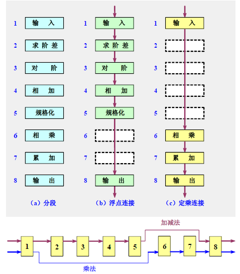
部件级流水线
浮点加法流水线
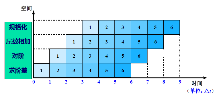
- 把浮点加法的全过程分解为求阶差、对阶 、尾数相加、规格化 4个子过程。理想情况:速度提高3倍

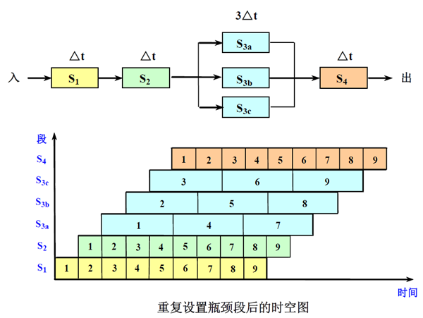
时空图
- 时空图中,横坐标代表时间,纵坐标代表流水线的各个段
流水线的分类
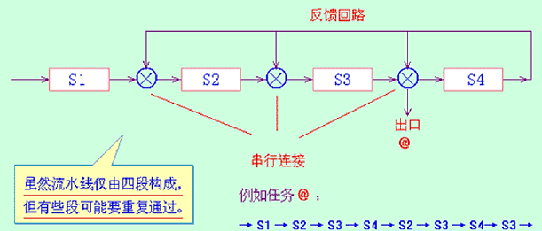
线性流水线与非线性流水线
- 按照流水线中是否有反馈回路来进行分类
- 线性流水线:流水线的各段串行连接,没有反馈回路。数据通过流水线中的各段时,每一个段最多只流过一次
- 非线性流水线:流水线中除了有串行的连接外,还有反馈回路
静态流水线与动态流水线
- 单功能流水线:流水线的各段之间连接固定不变、只能完成一种功能
- 多功能流水线:各段可以进行不同的连接,以实现不同的功能。进一步划分为:
- 静态流水线:同一时间内,各段只能按照同一种功能的连接方式工作。功能切换时,必须等前一个功能的任务都流出流水线
- 动态流水线:同一时间内,各段可以按照不同的方式连接,同时执行多种功能。允许某些段在执行某种运算时,另一些段在实现另一种功能
A Simple Implementation of A RISC Instruction Set In a Pipelined Fashion
The Basics of the RISC V Instruction Set
- All RISC architectures are characterized by a few key properties:
- All operations on data apply to data in registers and typically change the entire register (32 or 64 bits per register).
- The only operations that affect memory are load and store operations that move data from memory to a register or to memory from a register, respectively. Load and store operations that load or store less than a full register (e.g., a byte, 16 bits, or 32 bits) are often available.
- The instruction formats are few in number, with all instructions typically being one size (4 bytes).
- In RISC V, the register specifiers: rs1, rs2, and rd are always in the same place simplifying the control.
Three Classes of Instructions of MIPS64
- ALU instructions
- These instructions take either two registers or a register and a sign-extended immediate, operate on them, and store the result into a third register.
- Load and store instructions
- These instructions take a register source, called the b a s e base base
r e g i s t e r register register, and an immediate field, called the o f f s e t offset offset, as operands. The sum—called the e f f e c t i v e effective effective a d d r e s s address address—is used as a memory address.
- These instructions take a register source, called the b a s e base base
- Branches and jumps
- Branches are conditional transfers of control.
- Unconditional jumps.
A Simple Implementation of A RISC Instruction Set
Our implementation will focus only on a pipeline for an integer subset of a RISC architecture that consists of load-store word, branch, and integer ALU operations.
- Every instruction can be executed in 5 steps:
- Instruction Fetch cycle (IF)
- Fetch the current instruction from memory (Mostly Cache). (Using PC)
- Update the PC to the next sequential instruction by adding 4 (because each instruction is 4 bytes) to the PC.
- Instruction Decode/register fetch cycle (ID)
- Decode the instruction and read the registers corresponding to register source specifiers from the register file (寄存器堆,即一组寄存器) (e.g.
IR6..10->A,IR11..15->B,Imm(立即数)).- Decoding is done in parallel with reading registers, which is possible because the register specifiers are at a fixed location in a RISC architecture. This technique is known as fixed-field decoding.
- Note that we may read a register we don’t use, which doesn’t help but also doesn’t hurt performance. (It does waste energy to read an unneeded register, and power-sensitive designs might avoid this.) For loads and ALU immediate operations, the immediate field is always in the same place, so we can easily sign extend it. (For a more complete implementation of RISC V, we would need to compute two different sign-extended values, because the immediate field for store is in a different location.)
- Do the equality test on the registers as they are read, for a possible branch. (分支预判的准备工作) Sign-extend the offset field of the instruction in case it is needed. Compute the possible branch target address by adding the sign-extended offset to the incremented PC. (这部分后面在讲 Branch Hazards 的时候会讲到为什么这么设计;在讲到 Branch Hazards 之前先假设条件判断和有效地址计算是在 EX 段进行,PC 值的更新在 MEM 段进行)
- Decode the instruction and read the registers corresponding to register source specifiers from the register file (寄存器堆,即一组寄存器) (e.g.
- EXecution/effective address cycle (EX)
- The ALU performs one of the following functions on the operands prepared in the prior cycle
- Memory reference—The ALU adds the base register and the offset to form the effective address.
- Register-Register ALU instruction—The ALU performs the operation specified by the ALU opcode on the values read from the register file.
- Register-Immediate ALU instruction—The ALU performs the operation specified by the ALU opcode on the first value read from the register file and the sign-extended immediate.
- Conditional branch—Determine whether the condition is true.
- In a load-store architecture the effective address and execution cycles can be combined into a single clock cycle, because no instruction needs to simultaneously calculate a data address and perform an operation on the data.
- The ALU performs one of the following functions on the operands prepared in the prior cycle
- Memory access (MEM):
- If the instruction is a load, the memory does a read using the effective address computed in the previous cycle.
- If it is a store, then the memory writes the data from the second register read from the register file using the effective address.
- Write-back cycle (WB):
- Write the result into the register file
- From the memory system (for a load)
- From the ALU (for an Register-Register ALU instruction)
- Write the result into the register file
- Instruction Fetch cycle (IF)
- In this implementation, every instructions takes at most 5 clock cycles
- branch instructions require three cycles
- store instructions require four cycles
- all other instructions require five cycles
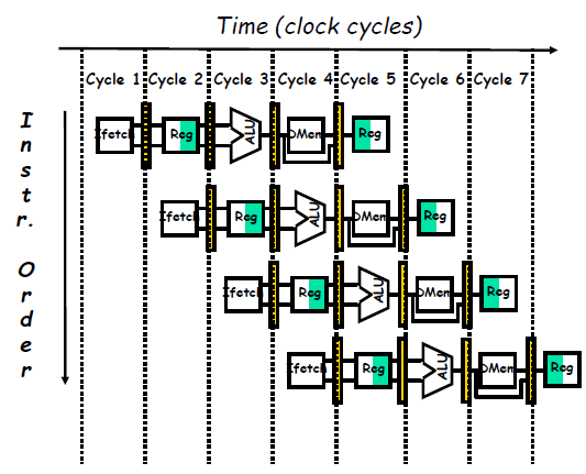
The Classic Five-Stage Pipeline for a RISC Processor
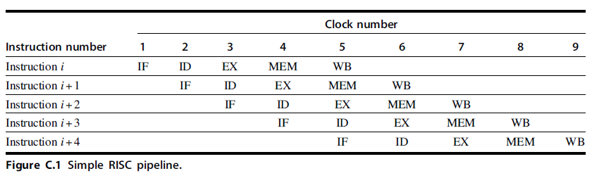
- You may find it hard to believe that pipelining is as simple as this; it’s not. In this and the following sections, we will make our RISC pipeline “real” by dealing with problems that pipelining introduces.
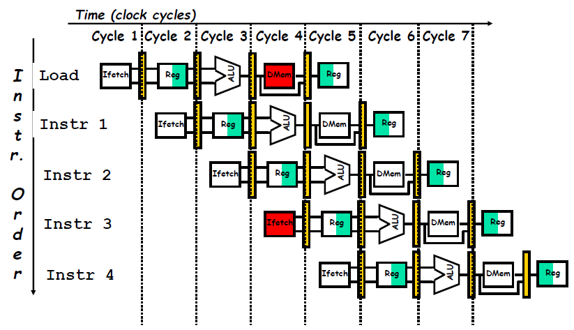
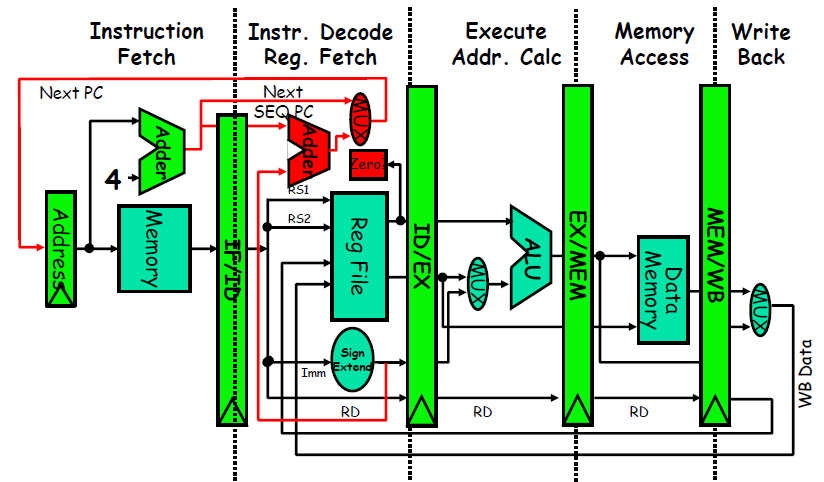
Pipeline as Data Paths Shifted in Time
- To start with, we have to determine what happens on every clock cycle of the processor and make sure we don’t try to perform two different operations with the same data path resource on the same clock cycle.
- For example, a single ALU cannot be asked to compute an effective address and perform a subtract operation at the same time.
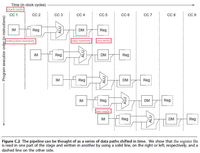
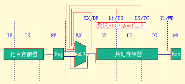
- Figure C.2 shows a simplified version of a RISC data path drawn in pipeline fashion. This figure shows the overlap among the parts of the data path, with clock cycle 5 (CC 5) showing the steady-state situation.
- First, we use separate instruction and data memories, which we would typically implement with separate instruction and data caches. The use of separate caches eliminates a conflict for a single memory that would arise between instruction fetch and data memory access (避免结构冲突).
- Second, the register file is used in the two stages: one for reading in ID and one for writing in WB. Hence, we need to perform two reads and one write every clock cycle. To handle reads and a write to the same register, we perform the register write in the first half of the clock cycle and the read in the second half.
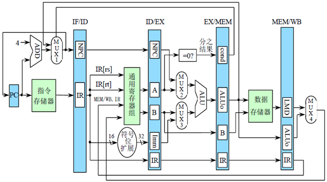
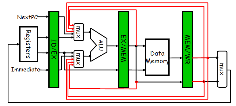
Pipeline Registers / Latches between Successive Pipeline Stages
- Play a critical role of carrying data for a given instruction from one stage to the other.
- The edge-triggered property of registers is critical. Otherwise, the data from one instruction could interfere with the execution of another!
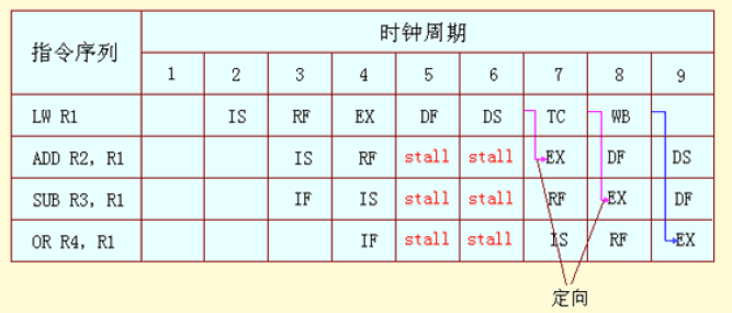
流水线寄存器的构成
- 流水线寄存器组中所包含的寄存器的命名类似于域的命名。即:
寄存器组.寄存器名- 如
ID段和EX段之间的流水线寄存器组中的IR寄存器的名称为ID/EX.IR - 关于下图的一些解释:
new pc是经过计算后的新的pc值;cond为 条件分支判断的结果;LMD为 load memory data (注意,每一个部件里执行的都是不一样的指令)
- 如
- 流水线寄存器的数据通路-IF

- MUX1:若
EX/MEM.IR中的指令是分支指令,而且EX/MEM.cond为真,则选EX/MEM.ALUo,即分支目标地址,否则选PC+4
- MUX1:若
- 流水线寄存器的数据通路-ID

- 流水线寄存器的数据通路-EX


- MUX2:若
ID/EX.IR中的指令是分支指令,则选择ID/EX.NPC,否则选ID/EX.A - MUX3:若
ID/EX.IR中的指令是寄存器-寄存器型 ALU 指令,则选ID/EX.B,否则选ID/EX.Imm
- MUX2:若
- 流水线寄存器的数据通路-MEM

- 流水线寄存器的数据通路-WB


- MUX4:若
MEM/WB.IR中的指令是load指令,则选MEM/WB.LMD,否则选MEM/WB.ALUo
- MUX4:若
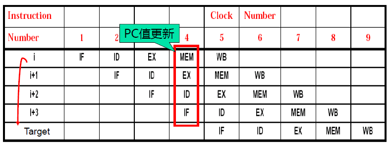
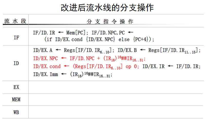
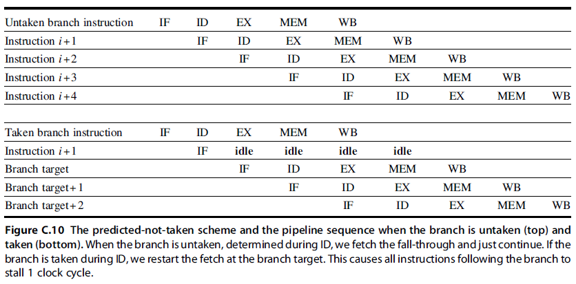
分支指令的影响
- 顺序执行时
PC+4必须在 IF 段完成,每个周期启动新指令 - 若分支指令条件为真,在 MEM 段进行 PC 值的更新
- 增加多路选择器,把所有改变 PC 值的操作都放在 IF 段进行
- 第
i+3条指令的PC+4不做 (说明第i条指令跳转条件为真),i+1,i+2,i+3指令均作废
The Major Hurdle of Pipelining—Pipeline Hazards (冲突)
- Hazards prevent next instruction from executing during its designated clock cycle.
- Structural hazards (结构冲突): attempt to use the same hardware to do two different things at once (划分的子任务不独立)
- Data hazards (数据冲突): Instruction depends on result of prior instruction still in the pipeline
- Control hazards (控制冲突): Caused by delay between the fetching of instructions and decisions about changes in control flow (branches and jumps).
在遇到条件转移指令时,存在是顺序执行还是转移执行两种可能
(提前执行一条条件转移指令时,要用到前面指令执行的结果,而因为流水线的关系前面指令的结果还没得出来…提前使用某个标志位可能会导致判断错误)
Stall 停顿 (also called bubble)
- Avoiding a hazard often requires that some instructions in the pipeline be allowed to proceed while others are delayed
- When an instruction is stalled
- Instructions issued later than this instruction are stalled. As a result, no new instructions are fetched during the stall.
- Instructions issued earlier than this instruction must continue
Structural Hazards
Why it happens?
- Some functional unit is not fully pipelined
- A sequence of instructions using that unpipelined unit cannot proceed at the rate of one per clock cycle
- Some resource has not been duplicated enough to allow all combinations of instructions in the pipeline to execute
Structural Hazards 是相对来说好解决的;如果不考虑成本的话,多设置几个部件就行了
One Memory Port/Structural Hazards (若指令/数据存取不分开)
“bubble” the pipe
Data Hazards
- Data hazards occur when the pipeline changes the order of read/write accesses to operands so that the order differs from the order seen by sequentially executing instructions on an unpipelined processor.
Three Generic Data Hazards
- Assume instruction i i i occurs in program order before instruction j j j and both instructions use register x x x, then there are three different types of hazards that can occur between i i i and j j j:
- (1) Read After Write (RAW): a read of register x x x by instruction j j j occurs before the write of register x x x by instruction i i i.
- Data Hazard on R 1 R_1 R1 (The
subandandinstruction creates a possible RAW hazard)
- Caused by a “Dependence” (in compiler nomenclature 术语) This hazard results from an actual need for communication.
- Data Hazard on R 1 R_1 R1 (The
- (2) Write After Read (WAR): a read of register x x x by instruction i i i occurs after a write of register x x x by instruction j j j

- Called an “anti-dependence” by compiler writers. This results from reuse of the name “ r 1 r_1 r1”.
- Can’t happen in MIPS 5 stage pipeline because: All instructions take 5 stages, and Reads are always in stage 2, and Writes are always in stage 5
- Write After Write (WAW): a write of register x x x by instruction i i i occurs after a write of register x x x by instruction j j j. When this occurs, register x will have the wrong value going forward.

- Called an “output dependence” by compiler writers. This also results from the reuse of name “ r 1 r_1 r1”.
- Can’t happen in MIPS 5 stage pipeline because: All instructions take 5 stages, and Writes are always in stage 5
- (1) Read After Write (RAW): a read of register x x x by instruction j j j occurs before the write of register x x x by instruction i i i.
For now, we focus only on RAW hazards.
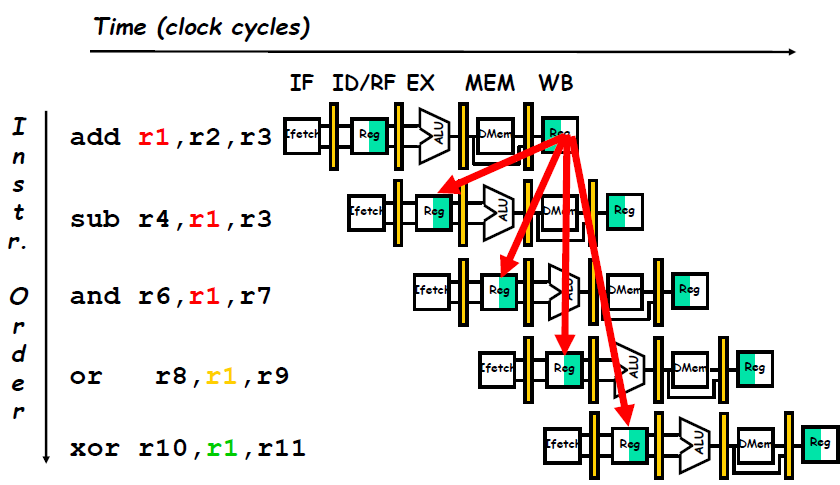
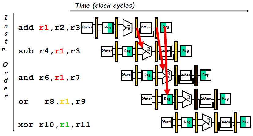
Minimizing Data Hazard Stalls by Forwarding
Forwarding (旁路): Bypassing (直接通路) or Short-circuiting (短路)
- The key insight in forwarding is that the result is not really needed by the
subuntil after theaddactually produces it. If the result can be moved from the pipeline register where theaddstores it to where thesubneeds it, then the need for a stall can be avoided. Using this observation, forwarding works as follows:- The ALU result from both the EX/MEM and MEM/WB pipeline registers is always fed back to the ALU inputs.
- If the forwarding hardware detects that the previous ALU operation has written the register corresponding to a source for the current ALU operation, control logic selects the forwarded result as the ALU input rather than the value read from the register file. We need to forward results not only from the immediately previous instruction but also possibly from an instruction that started two cycles earlier.
- Notice that with forwarding, if the
subis stalled, theaddwill be completed and the bypass will not be activated. This relationship is also true for the case of an interrupt between the two instructions.
- Notice that with forwarding, if the
- The ALU result from both the EX/MEM and MEM/WB pipeline registers is always fed back to the ALU inputs.
- Forwarding can be generalized to include passing a result directly to the functional unit that requires it:
- a result is forwarded from the pipeline register corresponding to the output of one unit to the input of another, rather than just from the result of a unit to the input of the same unit.
- a result is forwarded from the pipeline register corresponding to the output of one unit to the input of another, rather than just from the result of a unit to the input of the same unit.
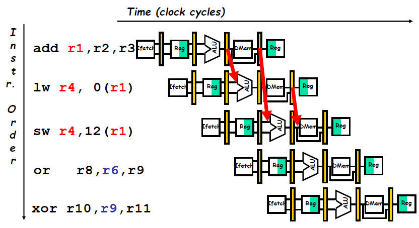
Data Hazard Even with Forwarding
- For the
subinstruction, the forwarded result arrives too late—at the end of a clock cycle, when it is needed at the beginning. This problem is solved by inserting a stall.
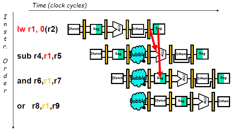
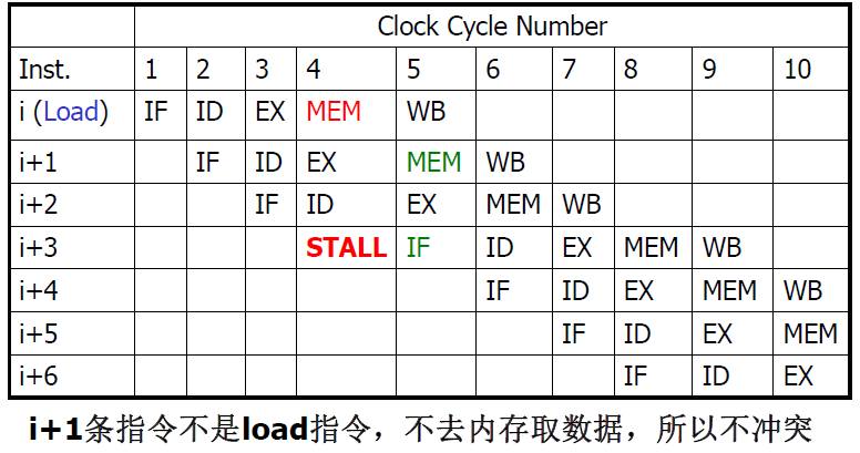
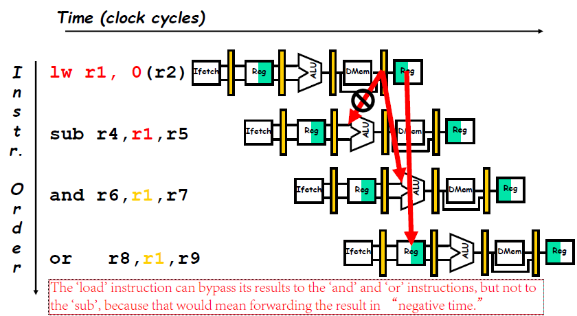
- 流水线相关硬件可以检测到的各种相关情况
- 如解决由
load指令引起的 RAW 相关的互锁 (pipeline interlock) (简称Load互锁) ,仅需把load指令的目的寄存器地址与load指令后的两条指令的源寄存器地址进行比较. In this case, the interlock stalls the pipeline, beginning with the instruction that wants to use the data until the source instruction produces it.
- 如解决由
Software Scheduling to Avoid Load Hazards
编译调度方法
- Try producing fast code for
 assuming
 a,b,c,d,e, andfin memory.

- 编译后如果生成 slow code,会导致暂停
Control Hazard on Branches
- Control hazards can cause a greater performance lose for our MIPS pipeline than do data hazards.
- If a branch changes the PC to its target address, it is a taken branch; if it falls through, it is not taken, or untaken.
Control Hazard on Branches Three Stage Stall
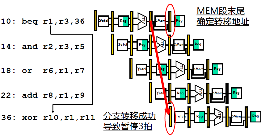
One stall cycle for every branch will yield a performance loss of 10% to 30% depending on the branch frequency
- Two part solution:
- Determine branch taken or not sooner, AND
- Compute taken branch address earlier
- MIPS branch tests if register = 0 or ≠ \neq = 0. MIPS Solution:
- Move Zero test to ID/RF stage
- Adder to calculate new PC in ID/RF stage (专门设置一个加法器而不用 ALU)
- 3-cycle penalty becomes 1-cycle penalty
Reducing Pipeline Branch Penalties
We discuss four simple compile time schemes in this subsection. In these four schemes the actions for a branch are static—they are fixed for each branch during the entire execution.
- (1) The simplest scheme is to stall until branch direction is clear.
- (2) Predict Branch Not Taken
- Treat every branch as not taken, executing successor instructions in sequence. (47% MIPS branches not taken on average)
- Here, care must be taken not to change the processor state until the branch outcome is definitely known. The complexity of this scheme arises from having to know when the state might be changed by an instruction and how to “back out” such a change. (由于在我们的 MIPS 5 段流水线中,只有 WB 段改变状态,因此满足这个要求)
- (3) Predict Branch Taken
- In our five-stage pipeline we don’t know the target address any earlier than we know the branch outcome, there is no advantage in this approach for this pipeline. MIPS still incurs 1 cycle branch penalty.
- Other machines: branch target known before outcome
- (4) Delayed Branch 分支延迟 (MIPS uses this)
- Define branch to take place AFTER a following instruction

- The sequential successor is in the branch delay slot (分支延迟槽). These instructiona are executed whether or not the branch is taken.
- Although it is possible to have a branch delay longer than one, in practice almost all processors with delayed branch have a single instruction delay; other techniques are used if the pipeline has a longer potential branch penalty.
- The job of the compiler is to make the successor instructions valid and useful.
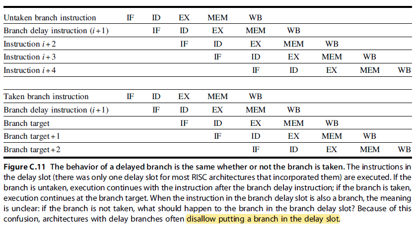
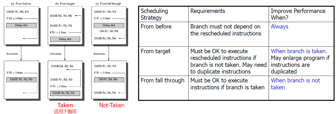
- Where to get instructions to fill branch delay slot?
- Before branch instruction
- From the target address: only valuable when branch taken
- From fall through: only valuable when branch not taken
- Compiler effectiveness for single branch delay slot:
- Fills about 60% of branch delay slots (40%找不到可以填入分支延迟槽的指令)
- About 80% of instructions executed in branch delay slots useful in computation
- About 50% (60% x 80%) of slots usefully filled (50% 事实上和第二种方法 “Predict Branch Not Taken” 的 47% 的效果是相当接近的)
- Canceling (Nullifying) Branch (分支取消或分支无效技术): To improve the ability of the compiler to fill branch delay slots Idea
- Associate each branch instruction the predicted direction
- If predicted, the instruction in the branch delay slot is simply executed as it would normal be with a delayed branch
- If unpredicted, the instruction in the branch delay slot is simply turned into a no-op
- Define branch to take place AFTER a following instruction
Although the delayed branch was useful for short simple pipelines at a time when hardware prediction was too expensive, the technique complicates implementation when there is dynamic branch prediction. For this reason, RISC V appropriately omitted delayed branches.
Pipelining Performance
流水线的性能
吞吐率 T P TP TP (ThroughPut)
- 吞吐率: 单位时间内流水线所完成指令或输出结果的数量
- Pipelining does not help latency of single task, it helps throughput of entire workload.
最大吞吐率 T P m a x TP_{max} TPmax
- 流水线在连续流动达到稳定状态后所得到的吞吐率
- 若流水线各段的时间相等,均为 △ t △t △t,则:
T P m a x = 1 / △ t TP_{max} = 1 /△t TPmax=1/△t - 若流水线各段的时间不等,则:
T P m a x = 1 max { △ t i } TP_{max} = \frac{1}{\max\{△t_i\}} TPmax=max{ △ti}1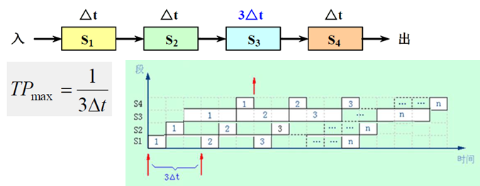
总的执行时间为 ∑ i = 1 k Δ t i + ( n − 1 ) Δ t j \sum_{i=1}^k Δt_i+(n-1)Δt_j ∑i=1kΔti+(n−1)Δtj;其中 ∑ i = 1 k Δ t i \sum_{i=1}^kΔt_i ∑i=1kΔti 为第一条指令的执行时间,之后每 Δ t j Δt_j Δtj 时间产生一条指令的结果
解决流水线瓶颈问题的常用方法
- (1) 细分瓶颈段: 把瓶颈段 S 3 S_3 S3 细分为 3 个子流水线段: S 3 a S_{3a} S3a, S 3 b S_{3b} S3b, S 3 c S_{3c} S3c

- (2) 重复设置瓶颈段: 缺点:控制逻辑比较复杂,所需的硬件增加了
实际吞吐率 TP
- 若流水线各段的时间相等,均为 △ t △t △t,假设流水线由 k k k 段组成,完成 n n n 个任务。则
T p = n k ⋅ Δ t + ( n − 1 ) ⋅ Δ t T_p=\frac{n}{k\cdot Δt+(n-1)\cdotΔt} Tp=k⋅Δt+(n−1)⋅Δtn - 若流水线各段的时间不等,则
T p = n ∑ i = 1 k Δ t i + ( n − 1 ) Δ t j , Δ t j = max { Δ t i } T_p=\frac{n}{\sum_{i=1}^k Δt_i+(n-1)Δt_j},\ \ \ \ \ \ \ \ Δt_j=\max\{Δt_i\} Tp=∑i=1kΔti+(n−1)Δtjn, Δtj=max{ Δti}
Example 1
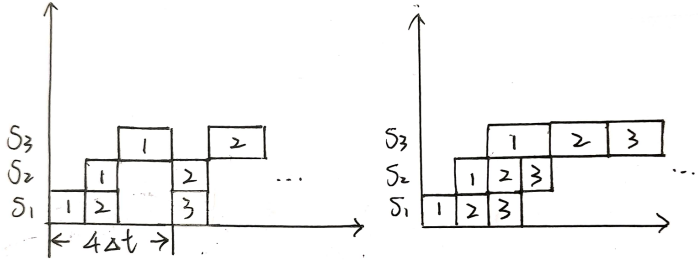
- 设一条指令的执行过程分为取指令、分析指令和执行指令3个阶段,所需时间分别为 △ t △t △t, △ t △t △t 和 2 △ t 2△t 2△t。分别求出下列情况下,连续执行 N N N 条指令所需的时间
- (1) 顺序执行方式;
- (2) 只有“取指令”和“分析指令”重叠;
- (3) 取指令,分析指令和执行指令重叠;
Answer
- (1) 每条指令执行时间为 △ t + △ t + 2 △ t = 4 △ t △t +△t + 2△t = 4△t △t+△t+2△t=4△t,连续执行 N N N 条时间为 4 N △ t 4N△t 4N△t
- (2) 4 △ t + ( N − 1 ) 3 △ t 4△t + (N-1)3△t 4△t+(N−1)3△t (左图)
- (3) 4 △ t + ( N − 1 ) 2 △ t 4△t + (N-1)2△t 4△t+(N−1)2△t (右图)
加速比 S p S_p Sp
- 加速比: 流水线的速度与等功能的非流水线的速度之比
S = T 非 流 水 T 流 水 S=\frac{T_{非流水}}{T_{流水}} S=T流水T非流水
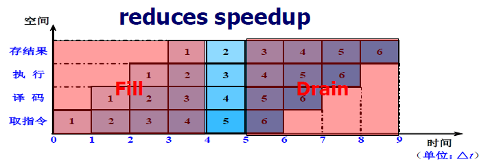
Potential speedup = Number of pipe stages
- If the stages are perfectly balanced and everything is perfect, then the time per instruction on the pipelined machine is equal to


- Unbalanced lengths of pipe stages reduces speedup
- Time to “fill” pipeline and time to “drain” it reduces speedup
- 若流水线为 k k k 段,且各段时间相等,均为 △ t △t △t,则:
S = T 非 流 水 T 流 水 = n k ⋅ Δ t k ⋅ Δ t + ( n − 1 ) ⋅ Δ t = n k k + n − 1 S=\frac{T_{非流水}}{T_{流水}}=\frac{ nk ·Δ t}{k ·Δ t + (n-1) ·Δ t}=\frac{nk}{k+n-1} S=T流水T非流水=k⋅Δt+(n−1)⋅Δtnk⋅Δt=k+n−1nk- n > > k n >> k n>>k 时, S ≈ k S ≈ k S≈k
- 流水线段数越多,加速比越高,但流水线段数并不能无限增加: (1) 流水线段数越多, 流水线寄存器也越多,CPU 的设计也会更加复杂;(2) 流水线段数越多, 就可以使整条流水线采用更短的周期工作,因此也需要更高的主频 (一个时钟周期就要完成一个流水段) (3) 受硬件制约,无法划分出那么多段的流水线
效率 E E E
- 效率: 流水线中各功能段的利用率
- 由于流水线有通过时间和排空时间,所以流水线的各段并不是一直满负荷地工作。故: E < 1 E <1 E<1
- 通过时间:第一个任务从进入流水线到流出结果所需的时间 (time to “fill” pipeline)
- 排空时间:最后一个任务从进入流水线到流出结果所需的时间。(time to “drain” pipeline)
- 从时空图上看,效率实际上就是 n n n 个任务所占的时空区与 k k k 个段总的时空区之比
- 若各段时间相等,则各段的效率 e i e_i ei 相等,即
e i = n Δ t 0 T 流 水 = n Δ t 0 k Δ t 0 + ( n − 1 ) Δ t 0 = n k + n − 1 , i = 1 , . . , k e_i=\frac{nΔt_0}{T_{流水}}=\frac{nΔt_0}{kΔt_0+(n-1)Δt_0}=\frac{n}{k+n-1},\ \ \ \ \ \ \ \ i=1,..,k ei=T流水nΔt0=kΔt0+(n−1)Δt0nΔt0=k+n−1n, i=1,..,k- 当 n > > k n >> k n>>k 时, E ≈ 1 E ≈ 1 E≈1: 流水技术适合于大量重复的时序过程,只有在输入端不断地提供任务,才能充分发挥流水线的效率
- 当各段时间不等时

Example 2
- Consider an unpipelined processor. Assume that it has a 1 ns clock cycle and that it uses 4 cycles for ALU operations and branches, 5 cycles for memory operations. Assume that the relative frequencies of these operations are 40%, 20%, and 40%, respectively. Suppose that due to clock skew (时钟偏移) and pipeline register delay, pipelining the processor adds 0.2 ns of overhead to the clock. Ignoring any other latency impact, how much speedup in the instruction execution rate will we gain from a pipeline?
- 流水寄存器需要建立时间和传输延迟
- 建立时间:在触发写操作的时钟信号到达之前,寄存器输入必须保持稳定的时间
- 传输延迟:时钟信号到达后到寄存器输出可用的时间
- 时钟偏移开销
- 流水线中,时钟到达各流水寄存器的最大差值时间(时钟到达各流水寄存器的时间不是完全相同)
- 流水寄存器需要建立时间和传输延迟
Answer
- Average instruction execution time on the unpipelined processor
= Clock cycle × Average CPI
= 1 ns × ((40% + 20%) × 4 + 40% × 5)
= 1 ns × 4.4 = 4.4 ns - In the pipelined implementation, the average instruction execution time will be 1 + 0.2 = 1.2 ns
- Thus, the speedup from pipelining is

Example 3
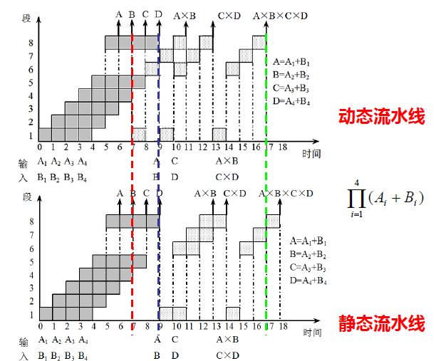
- 设在下图所示的静态流水线上计算
∏ i = 1 4 ( A i + B i ) \prod_{i=1}^4(A_i+B_i) i=1∏4(Ai+Bi)试计算其吞吐率、加速比和效率
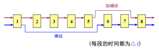
Answer
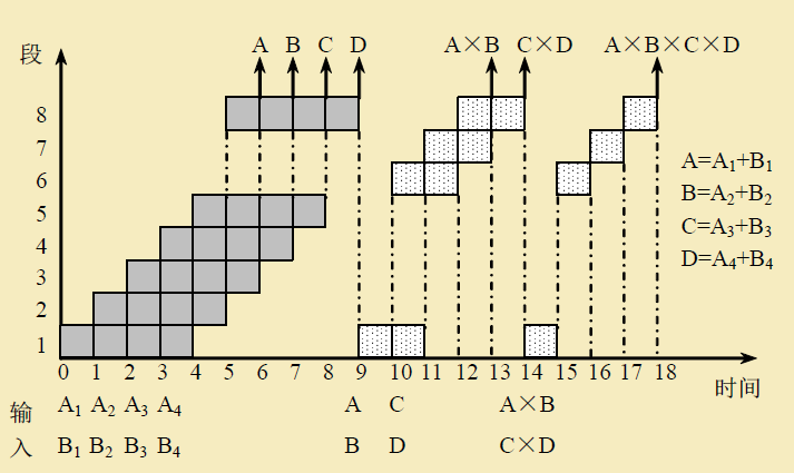
- T P = 7 18 △ t TP=\frac{7}{18△ t} TP=18△t7
- S = ( 4 × 6 + 3 × 4 ) △ t 18 △ t = 2 S=\frac{(4×6+3×4)△t }{18△t}= 2 S=18△t(4×6+3×4)△t=2
- E = 4 × 6 + 3 × 4 8 × 18 = 0.25 E=\frac{4×6+3×4}{8\times18}=0.25 E=8×184×6+3×4=0.25
Putting It All Together: The MIPS R4000 Pipeline
The MIPS architecture and RISC V are very similar, differing only in a few instructions, including a delayed branch in the MIPS ISA
超级流水线 (superpipelining)
- 超级流水线以增加流水线级数的方法来缩短机器周期,相同的时间内超级流水线执行了更多的机器指令
- 或者配置多个功能部件和指令译码电路,采用多条流水线并行处理,还有多个寄存器端口和总线,可以同时执行多个操作,因此比普通流水线执行的更快,在一个机器周期内可以流出多条指令
- The R4000 implements MIPS64 but uses a deeper pipeline. This deeper pipeline allows it to achieve higher clock rates by decomposing the five-stage integer pipeline into eight stages. Because cache access is particularly time critical, the extra pipeline stages come from decomposing the memory access.
Function of each stage
- IF—First half of instruction fetch; PC selection actually happens here, together with initiation of instruction cache access.
- IS—Second half of instruction fetch, complete instruction cache access.
- RF—Instruction decode and register fetch, hazard checking, and instruction cache hit detection.
- EX—Execution, which includes effective address calculation, ALU operation, and branch-target computation and condition evaluation.
- DF—Data fetch, first half of data cache access.
- DS—Second half of data fetch, completion of data cache access.
- 载入延迟为两个时钟周期
- TC—Tag check, to determine whether the data cache access hit.
- The TC stage is needed for data memory access, because we cannot write the data into the register until we know whether the cache access was a hit or not.
- 存储器管理部件 (MMU) 在 DF 和 DS 流水级把数据的虚拟地址变换成主存物理地址;然后,在 TC 流水级从数据 Cache 中读出数据的区号,并把读出的区号与变换成的主存物理地址进行比较;如果比较结果相等,则数据 Cache 命中
- WB—Write-back for loads and register-register operations.
- 将访存操作进一步分段,细分出了 IF, IS (取指令) 和 DF, DS, TC (读写数据) 这 5 段
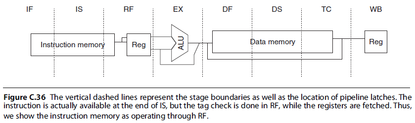
Notice that, although the instruction and data memory occupy multiple cycles, they are fully pipelined, so that a new instruction can start on every clock.
- This longer-latency pipeline increases both the load and branch delays.
- Load delay: 2 cycles (the data value is available at the end of DS)
- In fact, the pipeline uses the data before the cache hit detection is complete. If the tag check in TC indicates a miss, the pipeline is backed up a cycle, when the correct data are available.
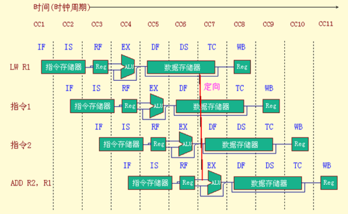
- Forwarding is required for the result of a load instruction to a destination that is three or four cycles later.
- ALU 输入有四个定向源
- In fact, the pipeline uses the data before the cache hit detection is complete. If the tag check in TC indicates a miss, the pipeline is backed up a cycle, when the correct data are available.
- Basic branch delay: 3 cycles (the branch condition is computed during EX)

- The MIPS architecture has a single-cycle delayed branch (一个分支延迟槽). The R4000 uses a predicted-not-taken strategy for the remaining two cycles of the branch delay.

- The MIPS architecture has a single-cycle delayed branch (一个分支延迟槽). The R4000 uses a predicted-not-taken strategy for the remaining two cycles of the branch delay.
After the R4000, all implementations of MIPS processor made use of dynamic branch prediction.
The Floating-Point Pipeline
- R4000 浮点部件: 1 个浮点除法器、1 个浮点乘法器、1 个浮点加法器
- The FP functional unit can be thought of as having eight different stages; these stages are combined in different orders to execute various FP operations. (多功能非线性流水线)
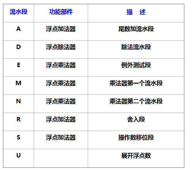
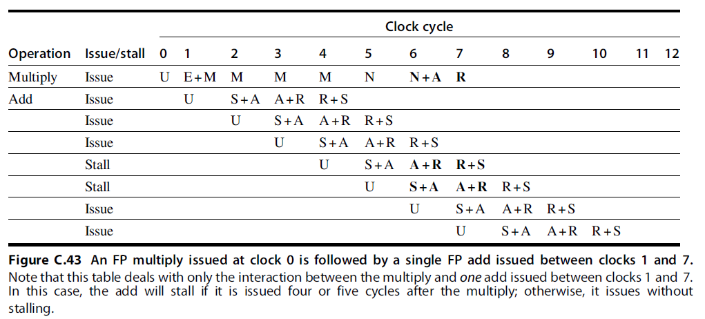
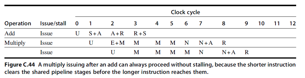
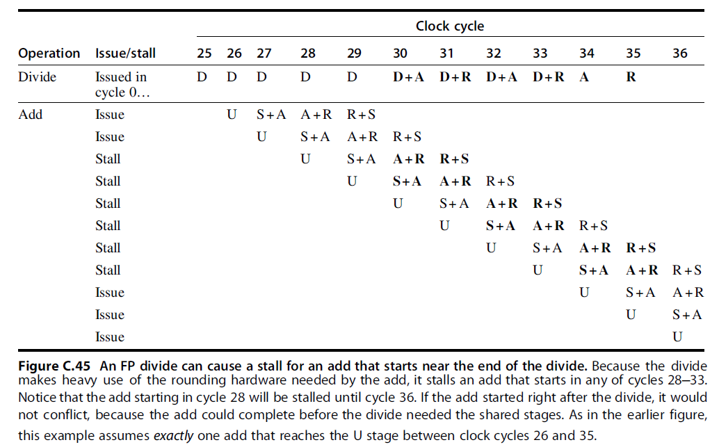
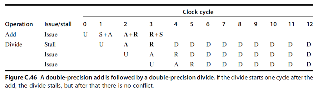
- 双精度浮点操作指令的延迟、启动间隔以及流水段的使用情况:

- Initiation interval (初始化间隔): 初始化两个连续的任务之间的时间间隔
- From the information in Figure C.42, we can determine whether a sequence of different, independent FP operations can issue without stalling.