本篇记录移植spi 接口的 mcp2515 can 芯片驱动的过程,mcp2515 芯片通过spi接口连接NUC980 的spi1接口,中断引脚接PA0中断。 此驱动移植过程主要分为如下几步。
第一步: 配置 linux 内核支持mcp2515的驱动,配置内容:
can 功能配置
[*] Networking support  --->
	<*>   CAN bus subsystem support  --->
		<*>   Raw CAN Protocol (raw access with CAN-ID filtering)
		<*>   Broadcast Manager CAN Protocol (with content filtering)
		CAN Device Drivers  --->
			<*> Platform CAN drivers with Netlink support
			[*]   CAN bit-timing calculation
			CAN SPI interfaces  --->
				<*> Microchip MCP251x and MCP25625 SPI CAN controllers
spi 接口配置
Device Drivers  --->
	[*] SPI support  --->
		<*>   Nuvoton NUC980 Series SPI Port 0
			SPI0 IO port selection (Port D)  --->
			SPI0 TX/RX by PDMA or not (Use PDMA)  --->
spi1 的 portD 口、分别对于 PD8/SS0, PD9/MOSI, PD10/MISO,PD11/CLK,中断引脚接PA0 。
第二步: 此样例平台未采用设备树方式,所有在 linux/arch/arm/mach-nuc980/dev.c 文件中,添加 设备节点内容。
+ #include <linux/can/platform/mcp251x.h>

+ static struct mcp251x_platform_data mcp251x_info = {


+ 	.oscillator_frequency = 8000000,
+ };

#if defined(CONFIG_MTD_M25P80) || defined(CONFIG_SPI_SPIDEV)
static struct spi_board_info nuc980_spi0_board_info[] __initdata = {


+	{


+		.modalias = "mcp2515",
+		.max_speed_hz = 2*1000*1000,		//  mcp2515 时钟 2MHz
+		.irq = IRQ_EXT0_A0,				//	中断编号 PA0 引脚
+		.bus_num = 1,					//  spi 1
+		.chip_select = 0,				//  use SS0
+		.mode = SPI_MODE_0,
+		.platform_data = &mcp251x_info,
+	},
};
#endif
第三步: 编译内核烧写至开发板中、确认配置can 网卡
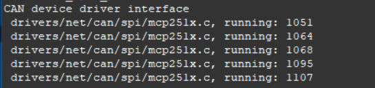
系统引导过程中,mcp251x的过程
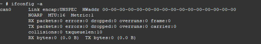
查看can网卡内容如下
下一篇博客会记录测试 can 通讯实验过程。